IECON'01: The 27th Annual Conference of the IEEE Industrial Electronics Society
Evolutionary Optimization of a Universal Motor Boris Benedičič, Tomaž Kmecl
Gregor Papa, Barbara Koroušić-Seljak
Strategic R&D Department Domel d.d. Otoki 21, SI-4228 Železniki SLOVENIA
Computer Systems Department “Jožef Stefan” Institute Jamova c. 39, SI-1000 Ljubljana SLOVENIA
[email protected],
[email protected]
[email protected],
[email protected]
Abstract – This paper presents a new designing procedure for the rotor and the stator of a universal motor for home appliances. It is based on a genetic algorithm (GA). The aim is to optimize the independent geometric parameters of the rotor/stator lamination to reduce the main motor's power losses, i.e., the iron and the copper losses. The GA proved to be a simple and efficient search and optimization method for solving the daily design problem in the industry. Using this procedure the motor's technical quality, expressed as efficiency, has been significantly improved.
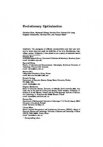
independent (like the external radius of the rotor, the rotor pole width, the rotor jag diameter, the stator jag radius, etc.) were varied. In addition to the above-mentioned independent variables there are also dependent variables, which were defined from independent ones. These dimension parameters (invariable, independent, and dependent parameters) are shown in Fig.1 and Fig.2. Among all invariable (fixed) parameters one parameter was extremely important from the motor-manufacturer’s point of view, namely the stator outer radius. The stator outer radius roughly defines the amount of material (iron and copper) used for the motor and consequently also the price of the motor. Since the stator outer radius (actually the product of width and length) was held constant during the optimization, all optimized motor solutions had similar mass.
I. INTRODUCTION Most home appliances with small motors, such as vacuum cleaners or mixers, are driven by universal motor. This is an AC series motor in which the same current passes through both the armature windings (rotor) and the field excitation windings (stator). A universal motor can operate either with an AC or with a DC power supply. Because of the widespread use of a universal motor, it is very important that the energy consumption of the motor (input power) is as low as possible, while the appliance still satisfies the needs of a user (output power). Hence, the technical quality of a universal motor can be expressed as efficiency, which is defined by the ratio of output power to input power. The efficiency depends on various losses: i.e., iron losses, copper losses and other losses like brush losses, friction losses and ventilation losses. The iron losses include the hysteresis losses and the eddy-current losses, primarily in the armature core and in the saturated parts of the stator core. The copper losses are the joule losses in the stator and in the rotor windings. The main losses, i.e., the iron and the copper losses can be reduced by optimization of rotor and stator geometry. Because of a high magnetic saturation of iron in universal motors, this is a highly non-linear problem. Due to the complexity of the solution originating in the non-linearity of the problem, the GA [1] was used for optimization of rotor and stator geometry.
III. DESIGN PROCEDURE According to the conventional (‘direct’) motor design procedure the initial estimation of the rotor and the stator geometry is based on experience. The appropriateness of a newly defined motor geometry is usually analyzed by means of a numerical simulation of the electromagnetic field. In our case, the analysis is performed with commercial software
II. ROTOR AND STATOR GEOMETRY The geometry of the rotor and the stator was defined parametrically. Some of the parameters were invariable, and were not altered due to the technological aspects. Only the dimensions of the variable parameters that were mutually
0-7803-7108-9/01/$10.00 (C)2001 IEEE
Fig. 1. Stator’s geometric parameters
19
IECON'01: The 27th Annual Conference of the IEEE Industrial Electronics Society
potential on every node of the finite-element mesh. From this potential, the values of flux density, field strength, and magnetic energy can be calculated. With a special module, electromagnetic torque on selected regions (rotor) can be calculated. The output power of a motor is a product of the electromagnetic torque and the angular velocity. A. Calculation of copper losses Copper losses per slot (stator and rotor) are calculated by the following equations:
J=
I⋅N , A
(1)
PCuSlot = I 2 ⋅ R = J 2 ⋅ A ⋅ ρ ⋅ l turn ,
where J is current density, I is current, N is number of turns, A is slot area, ρ is copper specific resistance and lturn is length of winding turn. The overall copper losses are as follows:
Fig. 2. Rotor’s geometric parameters
ANSYS [2], which applies a finite-element method with automatic finite-element mesh generation. In case the results of numerical simulation show an inconvenient electromagnetic field structure, the ‘direct’ design procedure is repeated until the motor geometry is optimized. The new motor design procedure described in this paper is a ‘direct’ system also, but it is based on the GA. This is a stochastic process providing a robust and yet flexible search in the wide and complex space of the problem solutions in order to find an optimal global solution in a short time. The concept of the applied design system can roughly be explained as follows: the GA provides a set of problem solutions (i.e., different configurations of rotor and stator independent geometrical parameters). In order to enable the calculation of a fitness value, each geometrical configuration is analyzed using the finite-element program. After the calculation of the fitness, reproduction of individuals and application of genetic operators on a new population are done. The GA repeats this procedure until a predefined number of iterations have been accomplished.
PCu =
∑P
CuSlot ,i
,
(3)
i
where i stands for each slot. B. Calculation of iron losses Because of the non-linear magnetic characteristic, the iron losses calculation is less exact. The iron losses are separated into two components: the hysteresis loss and the eddy current loss. An empirical formula for the hysteresis loss is defined as follows:
Ph = k h ⋅ B n ⋅ f ⋅ m ,
(4)
where kh is hysteresis material constant at 50 Hz, B is maximum magnetic flux density, f is frequency, m is mass, n is exponent between 1.6 and 2.0 (material dependent). The eddy current loss is defined as follows:
IV. CALCULATION OF LOSSES
Pe = k e ⋅ B 2 ⋅ f 2 ⋅ m ,
The finite-element program needs the following data in order to solve the electromagnetic problem: • well defined geometry of the analyzed element, • appropriate finite-element mesh, • material properties (iron B-H function, copper specific resistance), • density of the electric current in the conductor area. A typical run for such numerical problem needs about 30 iterations and takes approximately 7 min on Pentium III Computer Station to achieve a convergent numerical solution. The result of the solution is a magnetic vector
0-7803-7108-9/01/$10.00 (C)2001 IEEE
(2)
(5)
where ke is eddy-current material constant at 50 Hz. The frequency of magnetic field density in a stator is 50 Hz (frequency of power supply), while in a rotor the frequency is much higher and depends on the motor speed. If the motor were running at 50.000 min-1, the main rotor frequency would be 833 Hz. Since the eddy current losses depend on the square of the frequency, and the hysteresis losses increase linearly with the frequency, the main rotor iron losses are the eddy current losses. On the other hand, these losses depend on the square of the flux density. If the
20
IECON'01: The 27th Annual Conference of the IEEE Industrial Electronics Society
hysteresis losses in the rotor are neglected, the rotor iron losses can be calculated using (5) where B2 is obtained from the finite-element solution for each node. Consequently, the overall B2 of a rotor is calculated as an average of B2 of all rotor nodes. When calculating stator losses, hysteresis loss and eddy current loss must be summed up. Additionally, the factor n must be roughly estimated. Since the overall stator losses are approximately five times smaller than the rotor losses, even a non-exact estimation of a factor n does not have a significant influence on the overall motor iron losses calculation. Consequently, the iron losses of a motor can be expressed by the following equation: 2 PFe = k e ⋅ B 2 ⋅ f rot ⋅ mrot + 2 + k e ⋅ B 2 ⋅ f stat ⋅ m stat + k h ⋅ B 2 ⋅ f stat ⋅ mstat
,
a coding of the parameter set, not the parameters themselves. The algorithm employs an initial population of strings, which evolve to the next generation by probabilistic transition rules (randomized genetic operators) such as selection, crossover and mutation. The objective function evaluates the quality (fitness) of solutions coded as strings. This information is used to perform an effective search for better solutions. There is no need of other auxiliary knowledge. The GA tends to take advantage of the fittest solutions by giving them greater weight, and concentrating the search in the regions of the search space with likely improvement. The GA mechanism is as follows: (1) Initialize the population of strings. (2) Calculate the fitness for each member in the population using the objective function. (3) Select and reproduce individuals to form a new population according to each member's fitness. (4) Perform genetic operators on the population. (5) Go to step (2) until some condition is satisfied.
(6)
The sum of the iron and the copper losses PCuFe represents a so-called objective function for the GA.
PCuFe = PFe + PCu .
The GA is different from the traditional techniques because of its intrinsic parallelism (in evaluation function, selections) that allows working from a broad database of solutions in the search space simultaneously, climbing many peaks in parallel. Thus, the risk of converging to a local optimum is low. The random decisions made in the GA can be modeled using Markov chain analysis to show that each finite GA will always converge to its global optimum region [3]. In spite of its simplicity, the GA has proved to be an efficient method for solving various optimization and classification problems, in areas ranging from economics and game theory to control system design [4,5].
(7)
C. Calculation of other losses Beside the iron and the copper losses, three additional types of losses also take place in a universal motor, where: PBrush are brush losses, PVent are ventilation losses and PFrict are friction losses. All three types of losses mainly depend on the motor speed. Since the motor speed is equal for all solutions, these losses are considered constant in our analysis. Considering all the above-mentioned losses, the overall efficiency of a universal motor is defined as follows:
η=
P2 P2 + PBrush + PVent + PFrict + P CuFe
,
A. Genetic algorithm in rotor and stator design procedure Putting the new rotor and stator design procedure into practice the primary work was to define the encoding method of solution candidates, the genetic operators and the termination criteria. Also a method of evaluating the relative performance of solution candidates for identifying the better solutions had to be selected.
(8)
where P2 is output power. Consequently, the goal of the present investigation is to maximize this efficiency.
B. Encoding Parameters of the problem's search space were coded as strings over the alphabet — of real values. Using a symbolic presentation of a string with 11 characteristics (rotor and stator independent geometric parameters) gives:
V. GENETIC ALGORITHM Traditional search and optimization methods are slow in finding the solution in a complex problem's search space. For this reason, we decided to apply the GA to increase the efficiency of a universal motor with respect to the geometry of its rotor and stator unit. The other reason was that the problem is a non-linear one. The GA is based on a heuristic method, which requires little information to search effectively in a large search space. The GA codes parameters of the problem's search space as finite-length strings over some finite alphabet. It works with
0-7803-7108-9/01/$10.00 (C)2001 IEEE
S= s1s2s3s4s5s6s7s8s9s10s11 Here, each of the si represents a single stator or rotor geometrical parameter, where each characteristic may take on a real value from —. The rotor and the stator independent geometric parameters of an existing universal motor were used to form a starting
21
IECON'01: The 27th Annual Conference of the IEEE Industrial Electronics Society
string, which was reproduced (n-1)-times to generate an initial population of n-strings. A random value distributed linearly on ±∆ was added to each characteristic value of the starting string to define a reproduced string. Roughly speaking, the strings of this 'artificial genetic system' were analogous to chromosomes in biological systems. The entire set of strings upon which the GA operated was called a population.
random diversity in the population. Each string was subjected to the mutation operator. Mutation was performed on characteristic-by-characteristic basis, each characteristic mutating with a probability pm. Assuming that pm is a constant of 0.001, we expected 0.1% of characteristics parameters to undergo mutation during a given population. However, since a high mutation rate resulted in a random walk through the GA search space, pm had to be chosen to be somewhat low. There was also a possibility of annealing the mutation rate, where pm was a variable mutation probability. It was decreasing linearly with each new population. Namely, we assumed that each new population generally was more fit than the previous one. Such an approach was used to overcome a possible disruptive effect of mutation, and to speed up the convergence of the GA to the optimal solution in the final stages of the optimization.
C. Genetic operators To evolve the best solution candidate, the GA employed the genetic operators of selection, crossover and mutation for manipulating the strings in a population. The GA used these operators to combine the strings of the population in different arrangements, seeking a string that maximizes the objective function. This combination of strings resulted in a new population. The first genetic operator used by the GA for creating a new generation was selection. To create two offspring two strings had to be selected from the current population as parents. Most fit strings were selected for reproduction. We had applied the elitism strategy, where a randomly selected number of least-fit members of the current population were interchanged with the equal number of the best-ranked strings. Crossover proceeded in two steps. First, strings were mated randomly, using a given probability pc to pair off the couples. Second, mated string couples crossed over, using a random probability to select the one-point crossing sites. An integer position k was selected between 1 and the string length less one [1,l-1]. Swapping all characteristic values between the positions k+1 and l inclusively created two new strings. For example, considering strings A and B:
D. Fitness evaluation Following selection, reproduction, crossover, and mutation, the new population was ready to be evaluated. Therefore, each new string (solution candidate) created by the GA was decoded into a set of rotor and stator geometrical parameters, and its fitness was estimated running the finiteelement program (ANSYS). First, a finite-element numerical simulation was performed. Then, the iron and the copper power losses (using the equations of (6) and (3), respectively) were calculated. Their sum (see (7)) corresponded to the solution's fitness. Additional criteria for the solution evaluation was the price of the material needed to make a motor. This criterion was considered through the outer dimensions of the lamination. Since we wanted to keep the amount of material constant regarding the initial design we also made some optimizations with fixed outer dimensions.
A= a1a2a3a4 | a5a6a7a8a9a10a11 B= b1b2b3b4 | b5b6b7b8b9b10b11
E. Termination criteria
Suppose, choosing a random number between 1 and 10, we obtained k=4. The resulting crossover yielded two new strings A' and B':
The GA operated repetitively, with an idea that, on average, solutions of the population defining the current generation had to be as good (or better) at maximizing the fitness function as those of the previous generation. When a certain number of populations had been generated and evaluated, the system was assumed to be in a non-converging state. This criterion was a 'time-out' approach. The fittest member of the current generation at the time the GA terminated was taken to be the solution of the design problem.
A'= a1a2a3a4 | b5b6b7b8b9b10b11 B'= b1b2b3b4 | a5a6a7a8a9a10a11 Moreover, we might use a constant probability pr to select a case, in which the values of the swapped characteristics were calculated as a mean (average) value of the parent characteristic values.
a inew = binew =
a i + bi , 2
F. Parameter settings
(9)
Finding good settings for parameters of the GA that work for the problem was not a trivial task. Robust parameter settings had to be found for population size, number of generations, selection criteria and genetic operator probabilities:
While the first crossover approach assured that the child solutions preserved the 'genetic material' from both parents, the second one helped to seek for other solutions near to solutions appeared to be good. Mutation was a process by which strings resulting from selection and crossover were perturbed. It served to create
0-7803-7108-9/01/$10.00 (C)2001 IEEE
22
IECON'01: The 27th Annual Conference of the IEEE Industrial Electronics Society
TABLE I EVALUATION RESULTS
• If the population size was too small, the GA converged too quickly to a local optimal solution and might not find the best solution. On the other hand, large population required long time to converge to a region of the search space with significant improvement. • Applying the elitism strategy fitter solutions had greater chance of reproducing. But when the number of least-fit solutions to be exchanged with best-fit ones (the selection criteria) was too high, the GA was trapped too quickly in a local optimum solution. However, this number was subject to the population size. • Too low crossover probability preserves solutions to be interchanged and longer time is required to converge. This probability should be large enough to crossover almost all mated solutions. • Too high mutation probability introduced too much diversity and took longer time to reach an optimal solution. Too low mutation probability tended to miss some near-optimal solutions. Using the annealing strategy (the mutation probability was decreasing linearly with each new generation) the effects of too high or too low mutation could be overcome.
analytic calculation new
existing
new
input power
1044 W
1037 W
1100 W
1100 W
efficiency
70.0 %
74.5%
69.7%
72.6%
output power
731 W
773 W
767 W
799 W
power losses
313 W
264 W
333 W
301 W
efficiency difference
4.5%
2.9%
power losses difference
49 W
32 W
comparison with losses in the existing motor. The best solution results in a power losses reduction of 28%, and defines a motor with power losses of 144W (see Fig.4). The comparison of the magnetic flux densities in the existing and the optimized motors shows a clear reduction of areas with the highest levels of magnetic flux density in the optimized motor. In the second phase of the evaluation the outer dimensions of the motor lamination were fixed to ensure unchanged (not increased) material costs and allow the implementation of the motor into the same housing as before. As we can see in Tab. I, there is a difference in power losses and efficiency of the optimal motor due to our additional constraints. However the overall losses were reduced by 10%. After a prototype of the motor was made and measured we could evaluate the real values of losses and efficiency of the motor. These values are shown in Tab.I and are slightly different from the calculated ones. The main reason for the difference is the mentioned non-exact iron losses calculation. For both types of a motor the overall computation time was about 70 hours. Here the population size was 30, number of generation was 100 while the crossover and mutation probabilities were 70% and 0.1% respectively.
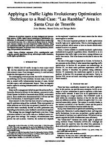
VI. EVALUATION First, the efficiency of an existing universal motor was calculated. An outline of the rotor/stator lamination of this motor is shown in Fig.3. The power losses of this motor were 200W and the output power 850W. In the outline, the levels of magnetic flux density through the rotor/stator lamination are shown. The darkest gray color indicates areas with the highest level of magnetic flux density, which results in high iron losses (2.3T). After several runs of the GA, a set of promising solution candidates was collected. For each candidate a finite-element numerical simulation followed by the calculation of the objective function value (fitness) was performed. Most of the solutions show a significant reduction of power losses in
Fig. 3. Initial outline of stator/rotor lamination
0-7803-7108-9/01/$10.00 (C)2001 IEEE
prototype measurement
existing
Fig. 4. New outline of stator/rotor lamination
23
IECON'01: The 27th Annual Conference of the IEEE Industrial Electronics Society
VII. CONCLUSION
REFERENCES
In this paper, an evolutionary optimization technique of designing universal motor for home appliances with constraints on the geometry of the rotor/stator lamination is presented. An approach using the GA in a very early motor design phase when an optimal configuration of the geometrical parameters has to be found is described. The GA generates sets of solution candidates, which are evaluated using finite-element method. We demonstrated that by repeating the process of generating sets of solutions in a way that the GA does, an optimal configuration with reduced power losses can be found in a very short time. Using the GA the power losses of an existing universal motor were reduced for at least 10% and up to 28%. Increasing the GA running time or setting its parameters more appropriately could still improve this result. However, parallel to the investigations on the geometry of the rotor and the stator components the mutual influence of other motor components should be investigated.
[1] T.Bäck, Evolutionary Algorithms in Theory and Practice. Oxford University Press, New York, 1996. [2] ANSYS User's Manual, ANSYS version 5.6, 2000. [3] C.L. Karr et al, “Solving inverse initial-value, boundary-value problems via genetic algorithm”, Engineering Applications of Artificial Intelligence, Vol. 13, No. 6, December 2000, pp. 625-633. [4] G.Papa, J.Šilc, “Using Simulated Annealing and Genetic Algorithm in the Automated Synthesis of Digital Systems”, Nikos E. Mastorakis (editor), Recent Advances in Circuits and Systems, World Scientific, Singapore, 1998, pp. 377-381. [5] B.Koroušić-Seljak, “Heuristic Methods for a Combinatorial Optimization Problem - Real-Time Task Scheduling Problem”, In C.H.Dagli et al (editors): Smart Engineering System Design: Neural Networks, Fuzzy Logic, Evolutionary Programming, Data Mining, and Complex Systems, ASME Press Series on Intelligent Engineering Systems through Artificial Neural Networks, Vol. 9, 1999, pp. 1041-1046.
0-7803-7108-9/01/$10.00 (C)2001 IEEE
24