Keywords: salient-pole synchronous machine, truiisfer functions, equivalent circuit modeling, SSFR testing. 1. INTRODUCTION. During a pancl session licld at ...
IEEE Transactions on Energy Conversion, Vol. 14, No. 4, December 1999
1209
EXPERIENCE WITH STANDSTILL FREQUENCY RESPONSE (SSFR) TESTING AND ANALYSIS OF SALIENT POLE SYNCHRONOUS MACHINES PREPARED BY IEEEPES WORKING GROUP #12 OF THE SYNCHRONOUS MACHINERY SUBCOMMITTEE OF THE ELECTRIC MACHINERY COMMITTEE Working Group Chair: P.L. Dandeiio, University of Toronto ; Secretary: H.C. Karmaker, GE Canada Working Group Members: C. Azuaje, EDELCA, Venezuela ; M. Glinkowski, ABB, USA ; I. Kamwa, Hydro Quebec ; S. Oliveira, Universidade Federal d o Rio de Janeiro, Brazil ; S.J. Salon, Rensselaer Polytechnic Institute, USA ;R.M. Saunders, University of California ; S. Umans, M.I.T. , USA
-
Abslracf Standstill Frcqucncy Response (SSFR) testing iind analysis of salient pole synchronous generators and motors performed by the members of the Working Group :ire summarized. The papers prescnted in II panel session ut the 1997 Winter Power Meeting [l] are coiiilciised into this Transactions papcr for the benefit of future rcseiirchcrs. The pertinent features of SSFR testing and annlysis o f salient polc machines arc described to point out the differences frum those of round rotor turbogenerators extensively publislicd in the literature.
Keywords: salient-pole synchronous machine, functions, equivalent circuit modeling, SSFR testing
truiisfer
1. INTRODUCTION During a pancl session licld at tlic I997 IEEEPES Winter Power Meeting, the csperieiiccs gaiiicd by Ilic coiilributing authors on SSFR testing and modcling of salient polc machines were reportcd. The inain cliariicteristics of tlic tcst inetliods and tlie conclusions of tlic authors arc siimmiirizcd in this paper for the bciielit of the rcaders iiitcrcslcd in applying these methods. Anotlicr objcctiw of the papcr is to present and publish tlie Coniinittcc Rcport i n the Transactions for inclusioii in Aitiirc rcvisioiis of tlie IEEE Std. 115(1995) 121. PE-481-EC-0-10.1998 A paper recommended and approved by the IEEE Electric Machinery Committee of the iEEE Power Engineering Society for publication in the IEEE Transactions on Energy Conversion. Manuscript submitted August 11, 1998; made available for printing November IO. 1998.
2. FEATURES OF SALIENT POLE MACHINES WHICH MAY lNFLUENCE SSFR TEST PROCEDURES
Tlicrc arc scvcral fcaturcs of salicnt pole machines wliicli caused llic Working Group to initiate this investigation. Tlicy are, ( I ) salicnt pole niachine topology produces a ratio ofLq/Ld ofapprosiniatcly 0.6 as opposed to nearly unity for cylindrical rotor machines; ( 2 ) salient poles are usually constructcd of stccl laniiiiations as opposed to forged-steel rotors mcd in cylindrical rotor machines; ( 3 ) tlie field winding i n cylindrical rotor inacliines is distributed wliercas i n tlic salicnt polc macliine it is coticcntrated, (4) most s;ilicnt polc machines liave ainortisseur windings in tlic pole faccs; (5) a sdient polc arinatiire winding is often designcd with a fractional numbcr of slots per pole per phase. These diucrenccs givc risc to diffcrent time constants, inductances and Iraiisfcr Ainctions, than those in cylindrical rotor niacliincs. A dcscriptiou of the inagnctomotive force (in* cliaracteristic of a salicnt pole niachine with a fractional slot winding is iocludcd in the Appendix for fiirtlier clarification.
Tlic positioning of tlic rotor for tlie salient pole inacliines h;is poscd cliallc~igesfor most of the authors. Instead of a coiiiplcle iii111 to be acliicved in the indnccd field voltage for tlic positioning of the rotor €or d-axis tcsts as recoininended i n IEEE Std. 11.5, the aiitliors had to be salisfled with the
miniminn induccd voltagc for the rotor positioning. Turning the rotor tliroligli 90 electrical degrces to achieve the q-axis position of a salicnt polc inacliinc is also not as clear cut as two or four polc tiirbogcnerator testing. For csample, in a salictil polc inachiiie with 12 poles, tlie polcs are 360172 or 5 dcgrccs :ipart mcchanically. To niovc the rotor from d-axis to q-asis. that is, 90 clcctrical degrees, tlic rotor has to be movcd by only 2.5 nicchanical degrees. Several authors dcscribc tlic iiicaiis of accoinplisliiiig tlie propcr position in tlicir spccilic tcsts.
088.5-8969/99/$10.00 0 1998 IEEE
~
1210
Armature Cannecrions
Orciilalor
d-axis Positioning
0 -
Field Shoned
Field Open
._Shoned
a-axis Positionins Field
f
..
S1ep (t I
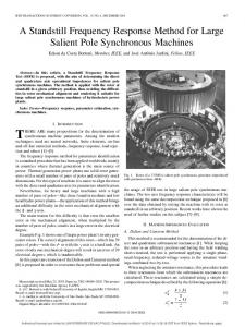
Fig.1. SSFR Test Set-up and Procedures 3. TEST RESULTS AND MODELS 3.1 Hydro Quebec Tests
3.2 Tests at M n c a p a Power Station in Venezuela
A series of tests was performed on a 6 MVA liydrogenerator at the D~mmondvillepower plant. Fig. 1 above sliows the test set-up.
SSFR tests were performed on two liydrogenerators rated 102 and 250 MVA at Macagua I1 power station.
For model identification in tlie d-asis, both two- and three-transfer-fUnction approaches with second and tliirdorder equivalent circuit models were used. In all cases, the desigii value of tlic turn ratio Nafd was used. Tlie resulting model is shown in Table 1 wliicli sliows the dynamic parameters to compare with design values. Fig. 2 sliows the goodness of fit for the operational inductances. Tlie measurements at very low frequencies are very oscillatory, specially for tlie q-asis tests. It is believed tliat the inaccuracies in tlie very low frequency tests are mainly due to the specifications and scltings of tlie spectrum analyzer, that is, tlie achievable resolution (mnnber of FiT bins), configuration of tlie analyzer (spectral window, numbcr of experiments to be avcraged. number of cycles in each test record prior to tlie FFT) and tlie absolute precision of tlie instrument. It is, therefore, suggested tliat despite the high measurement cost, it is preferable for the sake of accuracy to use at least 40 pointddecadc in the very low frequency range, such as, 1 to 100 mHz. Tlie eyxrience suggests lliat the users of the-test method should pay special attention to two areas for successful tests and model development, (I) careful rotor positioning for d-q ases and (2) acctirate data acquisition in low frequency range.
Both generators have fractional slot windings witb laminated poles and amortisseur windings. Tliere are no interpolar connections between the amortisseur windings of tlie consecutive poles. During positioning of the rotor, zero voltage on the field winding could not be achieved, so that tlie final position was decided by achieving the minimum induced voltage. The final rotor position was achieved by operating tlie rotor lifting pump wlucli made it easy to rotate the rotor with the use of proper pulling tools. During measurements, signals became noisier as the frequency was decreased below 0. I Hz. Tlie noisy signals at very low frequencies could be attribnted to tlie low value of test current (10 Amps RMS) and the performance of the power amplifier at very low frequencies. Sampling frequencies of 100 Hz in the range of O . O O l 4 . O l Hz and 200 Hz in the range of 0.01-0.1 Hz improved the results. Fig. 3 sliows tlie effect of changing the sampling frequency from 0.1 to 100 Kz in a 3 mHz signal. For 20 Hz and higher sampling frequencies, the magnitude and phase of the signal show convergence. Signals were noisier in the q-axis than the d-axis.
At very low frequencies, the impedance is also very sensitive to the armatiire resistance changes. A change of
1211
one micro-ohm could result in cliange of phase of about 1 degrees. A change of I deg. C in the winding tetnpcrature causes a change of 20 micro-ohms in the annature resistance. To study the possible effect of fractional slot winding, tests were performed at several rotor positions. NO significant differences in tlie test resulu were observed.
T ~ L1:EPARAMETERS OF DRUhlhlONDVILLE GENERATOR#3 (Fitting performed from 0.08 to 100 Hz) MVA = 6 p = S2 Zb = 2.8843R KV = 4.16 RPM = 138.5 H = 1.63
10''
IO'
I 0'
IO'
U2
Time constant i n seconds and renctwcc in p.u. I .5 times the ratlo of the armature to the field base currenis DC values measured using the bridge method *Measured at nominal current: xd = 1.Wip.u.: xq = 0.6Wp.u. 'Obtained by averaging [he magnitude of zqfjwl from I io 5 mHz.
'
Fig. 2. Goodness of fit of tlie models in Table 1 Fig. 4 sliows the measured operational inductances of 250 MVA generator. To identify the parameters of the model, curve-fitting was performed using MATLAB. For the d-axis, second order model is found adeauate. For the a-axis. liowever, a third order model produced the best fit.
1212
IO ?b5
01
IO
1
UMPUNQ
IC4
-115
mauENcy
-Mmnmhm -DMu
Fig 3. FFT of 3 mHz current vs sampling frequency
XO-
0.27
m
_ _ _ _ _ _- _- -- - - -_ _ ._ . - - - _ _ _ . ___________________----
TDa'
_ _ - _ -
a m
001
.
01
I
IO
IC4
tklz LQ HeasuRa
-L9
,m m
' WRae M m U r W
0.9.2
1.7W
*.*a
ssrn O.Du1
0.-
0.0414
0.llS
faclor
The minimum induced field voltage was used as .. the ~... intended rotor position, since a comp6te null could not be achieved.
M W -~ m m 3m Or Mmd
Fig. 4. Operational inductance of 250 MVA generator Table 2 shows the parameters calculated for the two generators. To calculate the parameters of the d-axis for unsaturated values. factors of 1.18 and 1.26 were applied to the 102 and 250 MVA generators respectively, based on the open circuit and shon circuit saturation tests, 3.3 Tests by
TDO'
(7 value aner appiiw =lummn . .U1
pm1
6
m
' a
o m
GE Canada
A hydrogenerator rated 1.4 MVA and a synchronous motor rated 654 kVA were tested by GE Canada and Queen's University. The hydrogenerator was tested at various rotor positions to study the effects of fractional-slot winding. No significant differences were observed in the frequency response characteristics measured at various rotor
Fig. 5 shows the d-axis operational inductance for five
rotor positions. The inductance values show significant variations for test frequencies less than 0.05 Hz. Tables 3 and 4 show the third order equivalent circuit parameters. Table 3 shows negative values of dierential leakage inductance, as theoretically postulated by Canay [3]. 3.4 Tests a t Camargos Power Station in Brazil
SSFR tests were performed on a 25 MVA hydrogenerator at Camargos power station in Brazil between 0.001 and 100
Hz. Ten points per decade nearly equally spaced in
a
logarithmic scale were used for the test frequency range, A mechanical system was developed to make the rotor alignment easier. An effective value of armature DC
1213
resistance was found by taking the average of the test values of Zd for 1 to 10 mHz. Two differential leakage reactances shown in Fig. 6 were used for identification o f a third order equivalent circuit model. Tables 5 and 6 show the d-axis and q-axis equivalent circuit parameters derived from the frequency response tests. Best curve-fit was obtained by using m n d order rotor representation for q-axis model and third order rotor representation for d-axis model. Differential leakage reactances were found negative.
different techniques. The results indicate tlrat tlle extraction' of machine dynamic parameters froln operational inductances presents engineering challenge. Three analysis types were conducted on the results of the SSFR tests, viz, direct method, analysis method based on one-cycle data and PROW analysis based on fractional-cycle data.
RMr
m--
.a I s I W S l l O N
e..-. WD PosmoN
.-v 3RD POSITION B.--.O~THPDS~~N ITHPOSmON P
0--0
E Y
0.01
01
I
FREQUWCY lHil 20
1
10
im
TABLE 3: D-AXIS PARAMETERS OF 1.4 MVA GENERATOR
1214
The analyses of the SSFR data by these methods led to the conclusion that the results are strongly sensitive to the noise in the signal and the value of the armature resistance used IO extract the operational inductance. Ra
Xfl d
XI
Fig. 7 shows the the impedance plot in the frequency range of 0 to 1 Hz The magnitude of impedance has a scatter of about 2.4% (0.6125 to 0.6275 Ohm) from the average value of 0.62 Ohm. The angle measurement is good to 0.2 degree. The resistance effectively masks the operational inductance and makes the latter ditficult to distinguish from the impedance.
Rf
/ \ I
I
PE" Fig. 6. D-Axis equivalent Circuit
TADLE 6 ()-AXIS PARAMETERS OF 25 MVA CAMARGOS GENERATOR
062 0615
4. CONCLUSIONS
The investigations performed on SSFR testing and analysis of salient-pole synchronous machines described in this paper have revealed the following characteristic features distinct from turbogenerators of round rotor construction.
T'q T'qo T"q T"qo
I 0.05538
1 0.07653 1 0.00461
I 0.00543 0.3884
I
I
I 0.05538
I 0.0330 I 0.0400
1 0.07653 0.03154
0.06424
0.5475
0.6988
Accurate rotor positioning for direct and quadrature axes may require particular attention owing to the large number of poles, especially in machines where fractional slot winding results in an h4MF distribution with unconventional periodicity pattern. In some cases, it may be necessary to use some locking mechanism to fix the m o r firmly at the intended position. One rotor position for each of the d- and q-axes has been found adequate for SSFR testing of salient-pole machines with fractional slot winding.
~
. . . .
1215
Highest possible measurement accuracy is required at very low frequencies to circumvent tlie poor signal-tonoise ratio resulting from the typical low values of dc armature resistance. Precise determining Uie pliase of the operational inductance is generally more difficult than determining the magnitude.
1. APPENDIX
To understand the mmf characteristics of a salient pole machine with fractional slot winding, the mmf diagram of fig. A for 4 kW 400Hz 14 poles 60 slots 3-phase machine may be used.
A second order model for the d-axis and a third order model in the q-axis are Seen to give tlie best fit of tlie test data. Differential leakage reactances in the equivalent circuit model are found negative. Precise determination of the armature dc resistance is very important for the low frequency testing. Since tlie tests require hours to complete at the very low frequecies, it is important to record the annature winding temperature tliroughout the entire duration of test in order to correct the resistance values for any temperature variation. An automated data acquisition system will also reduce man-hours necessary for completion of the tests. Sampling frequency during the data acquisition process is very important, especially when a small current is applied to a large machine, because tlie signals become very noisy at very low frequencies. 5. REFERENCES
[I] Experience with Standstill Frequency Response (SSFR) Testing and Analysis of Salient Pole Synchronous Machines, Proceedings of an Electric Machinery Committee Panel Session , organized by Synclironous Machinery Subcommittee Working Group #12, IEEE PES Winter Power Meeting, February 4, 1997.
-i
121 IEEE Guide: Test Procedures for SynclironousMachines, IEEE Std 115-1995, Part 11.
[3] I. M. Canay, “Causes of Discrepancies on Calculation of
Rotor Quantities and Exact Equivalent Diagrams of tlie Synchronous Machine”, IEEE Trans. on Power Apparatus and Systems, Vol. 88, No. 7, pp. I 114-1120, July 1969. 6. ACKNOWLEDGEMENTS
In addition lo the current Working Group members listed at the beginning of the paper, the other individuals who contributed to tlie panel session held on February 4, 1997 at the E E E P E S Winter Meeting are M. Pilote, Hydro Quebec ; D.Park, G.Dawson, A. Eastham , Queen’s University ; I. Chow, Rensselaer Polytechnic Institute ; R. Murphy, Macrodyne ; T. Cease, Tennessee Valley Authority.
Fig. A: Salient-pole machine MMF diagrams
1216
The left diagram is for the above machine where the number of slots per pole per phase (SPPP) is 1 3/7. It should be noted that it takes 14 poles before the winding repeats. For comparison, the same machine with 63 slots (1 H SPPP) will have MMF depicted in right diagram. The windings with the fraction !4 in SPPP may be considered integral since they repeat in a two-pole span. Note that in the left diagram for fractional SPPP, tlie positive peak MMF is 30 Amp-turns (At) for slots 1, 26 and 43 while it is 15 At for tlie remaining positive peaks. In the right diagram, however, all positive peak MMF’s are equal in magnitude to 20 At. Therefore. tlie fractional slot winding is apt to cause difficulty in aligning tlie rotor for the direct and quadrature axes positions for SSFR testing. In theory, it may be difficult to locate the direct axis by using the metliod prescribed for turbogenerators in IEEE Std. 115. The difficulty is due to the fact that when fractional SPPP windings are used for salient pole machines, tliere are multiple peaks of varying ampliludes in the m n d Fig. A sliows that tliere are seven “direct axes” not all equal in amplitude. On the otlier hand, for an integral SPPP winding as shown in fig. A, the mmfpeaks are all equal. This theory has, however, not been proven to be true for the tests reported in this paper. Mathematically, the distributed windings may be handled in two ways: (1) Fourier series or (2) incremental methods. Because !lie inductances are functions of tlie turns squared, the use of Fourier series for tlie turns becomes complicated in presence of the space harmonics associated with fractional SPPP windings.
For tlie two examples cited above, the per unit Fourier series for all harmonics larger tlian 10% of the largest liannonic are as follows. m-siot machine: N = 0.118 COS 38 + 1.0 ms 78 + 0.117 COS 98 + 0.162 COS 1IQ +. n . 1 1 7 ~I S~Q + O . I I ~ C O1 ~5 8
63 slot machine: N = 1.0
COS 78 ~
0 . COS 1 148 ~
Since the SSFR tests are also affected by the macliine time constants, some discussion of the inductance of the fractional slot windings will also clarify tlie cliaracteristics of SSFR tests of salient pole machines. The time constant is a ratio of self inductance to resistance of a winding. The selfinductance is obtained as ;1product of the number of turns squared times the permeance.
For cylidrical rotor machines, the permeance function is independent of the space angle. For salient pole maclunes, however, both the turns and permeance are functions of the space angle. Fig. B shows the permeance as a function of tlie space angle.
Lw--
Fig. B : Permeance vs. angle for 14 pole machine
The space harmonics are also expected to show more time constants tlian integral slot machines. However, they may not be crucial in simulation models as many of the amplitudes may not be significant to w a m n t concern.
(The material in this Appendix is based on the theory presented in the 1997 Panel presentation of Dr. R. M. Saunders).
1217
DISCUSSION Toshihisa Funahashi, (Senior Member, Meidensha Corporation, Tokyo, 103-8515, Japan):
This paper describes 5 cases of salient pole synchronous machines SSFR testing and analysis experiences, which would be useful for &hue research. The authors’ comments on SSFR analysis method would be appreciated. 1) MATLAB was used in the analysis of Macagua power
station case. Which curve fitting method is used and how does it work? In the case of Camargos power station, three analysis types were used, namely, direct method, FFT analysis, and PRONY analysis. Which one is best fitted to the measurements? In other cases, which type of analysis method is used? 2) For 250 MVA hydro-generator in Macagua power station, the second order d-axis model and the third order q-axis model produced best results. While, in other cases, the third or second order d-axis model and the second order q-axis model are adequate. Could you have any physical explanation about the reason why the q-axis order is greater than d-axis order in Macagua case? 3) For 25MVA generator in TVA, two mutual leakage
inductances, Xfld and Xfl2d appeared in d-axis of the third order equivalent circuit model. In some literature, only one differential inductance Xfl2d appears[A]-[D]. Which way is preferred for the best identification? [A] J.L.Kirtley, “On Turbine-Generator Rotor Equivalent Circuits”, IEEE Trans. on Power Systems, Vo1.9, No.1, February 1994, pp.262-271 [B] I.Kamwa and P.Viarouge, “On Eqivalent Circuit Structures for Empirical Modeling of TurbineGenerators”, IEEE Trans. on Energy Conversion, Vo1.9, N0.3, September 1994, pp.579-592 [C] S.Hensche1 and H.W.Domme1, “Noniterative Synchronous Machine Parameter Identification &om
Frequency Response Tests”, IEEE Preprint number PE003-PWRS-0-05-1998, May, 1998 [D] G.R.Selmon and M.L.Awad, “On Equivalent Circuit Modeling for Syncheonous Machines”, IEEE Preprint number PE-129EC-0-06-1998,June, 1998 Closure: The Working Group wishes to thank Mr. Funabashi for his discussion. This reply by Chair P.L. Dandeno to his questions is based on the opinions of several members of the group. The methods of cnwe fitting are numerous, but we feel the direct, or “least squares” method is best suited for frequency domain analysis. “Prony” is more suitable for time domain work. The least square approach is essentially a non-linear constraint type of optimization. In addition, various weigbtings (1, 2, etc.) for &(S) and sG(s) can be used in summing up the errors in the d-axis curve fitting process. This is also discussed in Chapter 12 (and its appendices) of IEEE Std 115 (1995). The fact that a third order model is sometimes preferable (e.g. Macagua) for the best fit of q-axis data has been noted by the Working Group. Basically this implies that there are no physically identifiable “circuits” with specific LIR ratios in the q-axis, as compared with the d axis (for example the field). Thus, the first break point in the q axis is between 0.1 and 1.0 Hz, as opposed to near 0.01 Hz in the direct axis first breakpoint. This applies especially to turboaltemators, but this phenomena appears to be present, for the q axis, in hydro generators too. Either one or two differential leakage reactances (Lfld and Lf12d) can be used, in the direct axis. As a minimum one such reactance is necessary to properly identify the field circuit in such SSFR-derived models. The physical interpretation of such differential inductances (or reactances) is also mentioned in one of the discussions in MI. Funabashi’ list of references (Ref. #3 by authors Kamwa and Viarouge, on equivalent circuit structures, etc.).