Recent Trends in Fluid Mechanics ISSN: 2455-1961(online) Volume 3, Issue 2 www.stmjournals.com
Experimental Setup to Evaluate Force Exerted by Water Jet Entering Tangentially on Curved Surface Rex Colaco*, Joy Moraes, Avanti Kadam, Viraj Parmar, Shivaji Shelar, Bhushan Sonawane Department of Mechanical Engineering, John College of Engineering and Technology, Palghar, Maharashtra, India
Abstract The purpose of this paper is to design and implement an experimental setup to find the value of vertical and horizontal forces when water jet impacts tangentially on a curved surface of 30, 45 and 600. The paper gives design details of all components designed using SolidWorks and their assembly to get the final experimental setup, which is to be used to find the value of vertical and horizontal forces. Also the fabrication details of each component are explained. The results obtained, show the variation in magnitude of forces with respect to discharge. The tangential entry of jet is made possible with the component called nozzle holder that holds the three nozzles at an angle tangent to the inlet of the curved surface which plays a vital role in achieving results with minimum error. The value of parameter that is used in calculation of practical forces is recorded on a spring-mass system designed for the setup. Keywords: Vertical and horizontal forces, tangential water jet impact, spring-mass system.
*Author for Correspondence E-mail:
[email protected]
INTRODUCTION One of the important components of power generating device is its blades. In earlier times, the turbines would have flat plates on which water would be impacted. Due to this impact, there would be a loss of energy. The wheel velocity would be half the water flow velocity and also due to impact, there would be generation of heat due to which the efficiency of those turbines was less than 50%. Later, these were replaced with curved vanes with tangential entry of jet. This increased the efficiency of turbines up to 85% with high power generation. Further improvement was also made to develop axial and radial flow turbines for low head and high discharge by using vanes effectively as guide and runner vanes with tangential entry. Over the years, research is being going on to improve the efficiency by working on various factors like vane angle, friction of vanes, material selection and their proper designing. In this project, the analysis on forces and how to increase it in order to improve the efficiency and extract more power, has been done. This project deals with analysis of forces for tangential impact of jet on curved vanes and comparing the theoretical and practical values
of the forces obtained. Also various parameters which affect the efficiency of device like blade friction, blade angle, material and various other design parameters can be found. By modifying these parameters one can try to increase the magnitude of forces and thus improve overall efficiency.
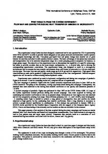
THEORETICAL ANALYSIS OF FORCES [1] Figure 1 shows the theoretical analysis of forces when water jet impacts on the curved plate tangentially. Consider a jet of velocity striking tangentially on an unsymmetrical curved plate. Here, Vx, Vy : Horizontal and vertical component of velocity of jet respectively; Ρ : Density of the fluid; A : Cross-section area of the nozzle; Fx, Fy : Force exerted on the curved plate in horizontal and vertical direction. Let tip angle be ɵ and ɸ. After resolving the initial and final velocities, we get; Initial velocity component at inlet are: Vx=Vcosɵ, Vy=Vsinɵ Final velocity component at exit are:
RTFM (2016) 12-20 © STM Journals 2016. All Rights Reserved
Page 12
Experimental Setup to Evaluate Force Exerted by Water Jet
Vx=Vcosɸ, Vy=Vsinɸ and Also, m=ρAV Using impulse momentum equation, the force exerted on plate in (X-X) and (Y-Y) directions will be: Fx=ρAV[Vcosɵ–(–Vcosɸ)] Fx=ρAV2(cosɵ+cosɸ) (1) Fy=ρAV[Vsinɵ–Vsinɸ] Fy=ρAV2(sinɵ–sinɸ) (2)
MODELLING OF COMPONENTS Curved Blades The curved blades used in the experiment have blade angles as 30, 45 and 60°. The material used for the blades is aluminium and have a diameter of 100 mm and thickness of about 3 mm [2]. For easy assembly and dismantling,
Colaco et al.
the blades are provided with threaded ends of 30 mm diameter on the extruded part on top of the blade. The Figures 2–4 show curved blades of 30, 45 and 60° blade angle. Nozzle Holder Figure 5 shows the nozzle holder with three nozzles fixed on metal plates riveted at 60, 45, and 300 from top to bottom respectively. The U-shaped extruded part at bottom allows continuous flow through pipes without causing bending in pipes. Fy Mechanism Figure 6 shows the mechanism used to find the y-component of force. It has a rod pivoted
Fig. 1: Theoretical Force Analysis.
Fig. 2: 30º Blade.
Fig. 3: 45º Blade.
RTFM (2016) 12-20 © STM Journals 2016. All Rights Reserved
Fig. 4: 60º Blade.
Page 13
Recent Trends in Fluid Mechanics Volume 3, Issue 2 ISSN: 2455-1961(online)
with the help of nut bolt assembly. One end of this pivoted rod has a rectangular plate with a slot cut in it and stoppers fixed to restrict the sliding motion of blade rod when the jet impacts on curved surface. The blade rod with its roller assembly is passed into the slot and rotated in such a way that the roller body rests on the rectangular plate and its sliding is prevented by stoppers. Unbalanced weight is hooked at the other end of the rod at a calculated distance. Spring-Mass System The forces exerted on the curved vanes will vary from 0.5 to 4.5 N. For this range of force, the stiffness calculated is around 0.4 N/mm. For this reason, springs of click pen having stiffness of 0.21 N/mm will be used in parallel arrangement. Figure 7 shows springs with guides to prevent the bending possibility of springs. Also a centimeter scale from 0–5 cm reading is fixed to top plate on which even the guides are fixed. The moving plate is pressed along the displaced body to give the value of displacement x.
Fig. 5: Nozzle Holder.
The other components that contribute to the assembly are: L-link with T-slot, Roller mechanism, Blade rod, Acrylic casing, Upper and lower plates, and Pipe assembly.
ASSEMBLY OF COMPONENTS The Figure 8 below shows the assembly which is used to find the x and y-components of the force. Here, the L-link is attached to the lower plate by nut bolt arrangement. The lower plate and upper plate are sealed with strong epoxy to prevent leakage. The L-link helps to restrict motion of the blade rod in horizontal direction, thus allowing to calculate x-component of the force. The other mechanism bolted to the other end of casing as seen in the Figure 8, is to find the y-component of force. While finding the xcomponent, the L-link is arranged parallel to the slot on the upper plate and the other mechanism is rotated at an angle away from the L-link for free movement of blade rod and vice versa.
Fig. 6: Fy Mechanism.
Fig. 7: Spring-Mass System.
Fig. 8: Experimental Setup to Evaluate Fx and Fy. RTFM (2016) 12-20 © STM Journals 2016. All Rights Reserved
Page 14
Experimental Setup to Evaluate Force Exerted by Water Jet
Colaco et al.
Slope = Stiffness
SPRING CALIBRATION The maximum force to be obtained in the experimental set up was around 5 N. The principle to be used in the experimental setup is F=k*x [3]. Where, F=force, k=stiffness of spring, x= displacement in spring. Therefore, for a force of 5 N at least 10 mm displacement is needed for flexibility in taking reading; which means a stiffness of around 0.5 N/mm was needed using spring of click ball point pen whose stiffness is 0.2 N/mm. Thus, using two springs in parallel to give a stiffness of around 0.4 N/mm would be used in this project. In order to verify the stiffness of spring, weights were added and its corresponding displacements were recorded and the graph for the same was plotted to calibrate the spring. The readings taken are as in Table 1 (Figure 9).
=k1=
y2 y
1
x2 x1
=
4.5 3 =0.375 N/mm. 12 8
This procedure was repeated three times to evaluate spring stiffness. The slope gives the stiffness of the spring. The average value of spring stiffness obtained is 0.394 N/mm, which is rounded off to around 0.4 N/mm.
PRACTICALLY PERFORMED EXPERIMENT Aim Aim is to calculate components of the forces when water jet impacts on the curved blades tangentially. Theory In this experimental setup we will find the two components of inclined forces i.e. horizontal
Table 1: Spring Calibration Data. Sr. No
Weight (gm)
Force (N)
Displacement (mm)
1
50
0.5
1
2
100
1
2
3
150
1.5
3
4
200
2
5
5
250
2.5
6
6
300
3
8
7
350
3.5
9
8
400
4
10
9
450
4.5
11
10
500
5
13
11
1000
10
16
Fig. 9: Force versus Displacement for Spring System.
RTFM (2016) 12-20 © STM Journals 2016. All Rights Reserved
Page 15
Recent Trends in Fluid Mechanics Volume 3, Issue 2 ISSN: 2455-1961(online)
force and vertical force. The resultant of these two forces is the inclined force (Figure 10). So, to find these forces, the concept that force is equal to product of displacement of spring and its stiffness, i.e. F=k*x is used. Where, k= stiffness of spring, x= displacement of spring. A jet of water will be impacted tangentially on curved blade at a particular angle. Due to this, the blade will try to move in the inclined direction of jet. Now in this case, initially the horizontal motion will be restricted so that the blade will move in vertical direction. So only Fy component will act on blade as horizontal motion will be restricted. Now using a device called the spring-mass system as shown below in Figure 11, the blade is to be pushed down to equilibrium position. Due to this, the spring will be displaced by some value (x).
Fig. 11: Calculation of Vertical Force, Fy.
Figure 11 shows the displacement in spring when the water jet just arrives at the blade and then lifts the blade to a particular distance.
Fig. 12: Equilibrium Position.
Fig. 10: Spring and Mass System.
Figure 12, explains the following procedure i.e. when the jet causes the blade to lift, a spring-mass system is externally used to push the blade rod and bring the blade to its initial position. This position is called the equilibrium position shown above. The force applied by the spring-mass system is equal to the force subjected by the jet on the blade i.e. F=Fy. Since the displacement (y) and the stiffness (k) of spring is found, one can find the value of force using the formula Fy=ky.
Fig. 13: Calculation of Horizontal Forces, Fx.
RTFM (2016) 12-20 © STM Journals 2016. All Rights Reserved
Page 16
Experimental Setup to Evaluate Force Exerted by Water Jet
In Figure 13, vertical motion is restricted by placing l-link on the upper plate and the displacement is calculated in the horizontal direction. The following procedure is similar to that while finding Fy. Also the force subjected by jet is equal to the force applied by spring-mass system bring blade back to its initial position achieving the equilibrium position. Now, as the displacement (x) and the stiffness (k) of spring is found, one can find the value of force using the formula, F=kx.
Colaco et al.
A=
π 2 xd 4
We know, Q=AxV Theoretically, we find Fx and Fy by the formulae, from Eq. (1) and (2), Fx=ρAV2(sinɵ–sinɸ), Fy=ρAV2(cosɵ+cosɸ). And practically Fx and Fy values are found by, Fx=k*x, Fy=k*y
Specifications Jet diameter/nozzle outlet diameter =8 mm Area of measuring tank =60x40 cm2 Spring stiffness =0.4 N/mm2 Motor power =0.37 KW/0.5 HP Rated Motor speed =2880 RPM Observations (Tables 2–4) x= Displacement recorded on spring-mass system while measuring horizontal component, y= Displacement recorded on spring-mass system while measuring vertical component.
Error in Fy=
Fy theo Fy prac Fy theo
Similarly, the error in vertical component can be calculated for different blades with different blade angle. Since the value of Fxtheo is zero, its comparison with practical values is not possible as error will tend to infinity. Note: For 30º blade, ɵ and ɸ=60º For 45º blade, ɵ and ɸ=45º For 60º blade, ɵ and ɸ=30º
RESULTS/CONCLUSIONS
Calculations For 30º blade,
1. The graphs obtained by practical and theoretical analysis of forces are in Figures 14–16.
lxbxh Q= t
Table 2: Observations and Results Data for 30º Blade. Sr. No.
Time t (sec)
Q (m3/s) x10-4
1.
35
3.24
2.
50
2.4
3.
57
2.1
4.17
V (m/s)
Theoretical (N)
Practical (N)
Fx
Fy
x
6.8
0
2.32
4.77
0
1.97
0
0.87
Error %
Fx
y
Fy
Fy
4
1.6
4
1.6
31.03
3
1.21
4
1.6
18.78
5
2
2
0.8
8.04
Table 3: Observations and Results Data for 45º Blade. Sr. No.
Time t (sec)
Q (m3/s) 10-4
1.
35
3.02
2.
50
2.4
3.
57
2.1
4.17
V (m/s)
Theoretical (N)
Practical (N)
Fx
Fy
X
Fx
y
6.8
0
3.28
6
2.4
4.77
0
1.61
4
1.6
0
1.23
4
1.6
Error % Fy
Fy
10
4
21.95
4
1.6
0.6
4
1.6
30
Table 4: Observations and Results Data for 60º Blade. Sr. No.
Time t (sec)
Q (m3/s) x10-4
V (m/s)
1.
35
3.02
2.
50
3.
57
Theoretical (N)
Practical (N)
Error %
Fx
Fy
X
Fx
y
Fy
Fy
6.8
0
4.023
9
3.6
10
4
0.57
2.4
4.77
0
1.97
5
2
6
2.4
21.82
2.1
4.17
0
1.5
4
1.6
4
1.6
6.66
RTFM (2016) 12-20 © STM Journals 2016. All Rights Reserved
Page 17
Recent Trends in Fluid Mechanics Volume 3, Issue 2 ISSN: 2455-1961(online)
Fig. 14: Effect of Discharge on Fy(theo).
Fig. 15: Effect of Discharge on Fy(prac).
RTFM (2016) 12-20 © STM Journals 2016. All Rights Reserved
Page 18
Experimental Setup to Evaluate Force Exerted by Water Jet
Colaco et al.
Fig. 16: Effect of Discharge on Fx(prac). 2. The Ftheo component is zero as the horizontal components cancel each other but when performed practically we get values. The reasons are as follows: The blades are not symmetrical as assumed in the theoretical calculations. The flow is assumed to be laminar but in practical case the flow is turbulent. 3. The value of forces increase with increase in the blade angle and discharge. 4. The error is as low as 0.6% for full discharge and as high as 30% for low discharge. The error between theoretical and practical values is because: The flow acts opposite to the force of gravity, thus reducing the actual force that impacts on the curved surface. The curved vanes have some slight discontinuities due to manufacturing errors, which offers resistance to the flow, reducing the velocity at the outlet. There may be a chance of parallax error while taking reading from spring mass
system. Human errors like taking water level rise reading or some loss of water due to leakage. 5. For full discharge condition, the maximum horizontal force was obtained for 60º blade i.e. 3.6 N and vertical force was also for 60º i.e. 4 N.
FUTURE SCOPE 1. In order to get more accurate readings, the blade surface can be coated with different materials to get friction factor as unity or research can be done on various surface finish processes or materials to get friction factor as one. 2. By using heater or compressor, we can perform this experiment by steam jet or compressed air entering tangentially on curved vanes. 3. The as shown in Figure can be used to give the jet entry. In this, only one nozzle and pipe is needed and the readings can be
RTFM (2016) 12-20 © STM Journals 2016. All Rights Reserved
Page 19
Recent Trends in Fluid Mechanics Volume 3, Issue 2 ISSN: 2455-1961(online)
taken for various blade angles and not restricting to only three blades. 4. By using 3D CAD model we can make theoretical analysis on cylindrical impeller vanes and by manufacturing the same we can do practical analysis [4].
REFERENCES 1. Gundale VA, Joshi GR. A Simplified 3D Model Approach in Constructing the Plain Vane Profile of a Radial Type Submersible Pump Impeller. Research Journal of Engineering Sciences. Jul 2013; 2(7): 33– 37p. 2. Padhy M, Senapati P. Turbine Blade Materials Used for the Power Plants Exposed to High Silt Erosion: A Review. International Conference on Hydropower
for Sustainable Development, Dehradun. Feb 05–07, 2015. 3. Bansal RK. A Textbook of Fluid Mechanics and Hydraulic Machines. 9th Edn. New Delhi-110002: Laxmi Publications (P) Ltd.; 2015. 4. Singh VP. Mechanical Vibration. 3rd Edn. Delhi-110032: Dhanpat Rai & Co. (P) Ltd.; 2011.
RTFM (2016) 12-20 © STM Journals 2016. All Rights Reserved
Cite this Article Rex Colaco, Joy Moraes, Avanti Kadam et al. Experimental Setup to Evaluate Force Exerted by Water Jet Entering Tangentially on Curved Surface. Recent Trends in Fluid Mechanics. 2016; 3(2): 12–20p.
Page 20