Malaysian Journal of Civil Engineering 19(1) : 17-25 (2007)
THE EFFECTS OF POROSITY OF SUBMERGED BREAKWATER STRUCTURES ON NON-BREAKING WAVE TRANSFORMATIONS Faridah Jaffar Sidek1,* , Muhammad Al-Jeffry Abdul Wahab2 1
Coastal & Offshore Engineering Institute, Universiti Teknologi Malaysia City Campus, Jalan Semarak, 54100 Kuala Lumpur, Malaysia 2 Faculty of Civil Engineering, Universiti Teknologi Malaysia, 81310 Skudai, Johor Bahru, Malaysia * Corresponding Author :
[email protected]
Abstract : Development of an innovative porous submerged breakwater structure which could be used for the purpose of coastal restoration is underway in the Coastal & Offshore Engineering Institute’s research laboratory. Prior to developing the structure, laboratory investigations on models (typifying porous submerged breakwater structures) that could provide experimental information of the influence of porosity on non-breaking wave transformations have been undertaken. A series of tests to study the effect of porosity of submerged breakwater model structures on the process of non-breaking wave transformations have been carried out. A hollow framework-shaped test model was used. Three models each with three different porosities ranging from 0.40 to 0.80 were constructed. From laboratory tests, results obtained have been analysed to check the performance of the models to attenuate waves. Test results have indicated that the transmission coefficient, KT increased with increasing model porosity. The wave reflection coefficient, KR of the model tested ranged from 0.01 to 0.31. Energy loss of the primary waves was found to be highest when the parameter kd was equal to 1.9 and lowest when the porosity of the model was found to be large. Keywords : Permeable breakwater; Porosity; Submerged breakwater; Wave attenuation; Wave Transmission Abstrak : Kerja-kerja untuk membangunkan satu pemecah ombak tenggelam yang berliang untuk kegunaan pemulihan pantai secara inovatif sedang dilaksanakan di makmal penyelidikan Institut Kejuruteraan Pantai dan Lepas Pantai. Sebelum merekabentuk struktur itu, kajian makmal ke atas model kajian yang mencontohi struktur pemecah ombak poros ditenggelami yang dapat mengesahkan pengaruh keliangan terhadap kelemahan tenaga ombak telah dikaji. Satu siri ujian yang merangkumi kajian untuk memperoleh maklumat tentang pengaruh keliangan pada struktur tersebut terhadap proses penghantaran ombak yang tidak pecah telah dijalankan. Model kajian yang merupakan rangka yang berongga telah digunakan. Tiga model pemecah ombak berliang yang bergeomatrikan tiga nilai keliangan yang berbeza dari 0.40 to 0.80 telah dibina. Daripada kajian makmal, hasil yang diperolehi telah dianalisis untuk memantau prestasi model kajian dalam melemahkan tenaga ombak. Hasil kajian menunjukkan bahawa koefisien penghantaran, KTt, bertambah dengan peningkatan nilai keliangan. Koefisien pantulan ombak, KR didapati berada di dalam julat 0.01 hingga 0.31. Kehilangan tenaga ombak adalah tinggi bila parameter kd adalah bersamaan dengan 1.9 dan rendah bila keliangan adalah besar.
Malaysian Journal of Civil Engineering 19(1) : 17-25 (2007)
18
Katakunci : Pemecah ombak boleh telap; keliangan; pemecah ombak tenggelam; pelemahan tenaga ombak; transmisi ombak
1.0
Introduction
Breakwaters have been constructed along shorelines to decrease wave energy on its leeward side so as to reduce shoreline erosion. Wave energy dissipated in the lee of a submerged breakwater after transmission by the process of friction, wave breaking or wave reflection can be measured by determining the wave transmission coefficient, KT. The wave transmission coefficient is defined as the ratio of the transmitted wave height (Ht) shoreward of the breakwater to the incident wave height (Hi) seaward of the breakwater. In physical modelling, the value of KT is the parameter to illustrate the effectiveness of a low crested submerged breakwater to attenuate the waves. The larger the value of wave transmission coefficient obtained, the lesser is the wave attenuation and vice-versa. For the range where 0 < KT < 1, a value of zero would imply that there existed no transmission such as in the case of high or impermeable breakwaters. Whilst, a value of one would infer that there existed complete transmission such as in the case of the absence of a breakwater. According to Pilarczyk (2003) low crested and submerged structures, such as the detached breakwaters and artificial reefs have been commonly used on their own or in combination with artificial sand nourishment to protect coastlines. The construction of these structures allowed the hydraulic loading on the shoreline to be reduced to a required level so that the dynamic equilibrium of the shoreline could be maintained. In order to achieve this goal, the structures have been designed to allow the transmission of a certain amount of wave energy over the structure by overtopping and also some transmission through the porous structure or through wave breaking and energy dissipation on the shallow crest of the submerged structures. Black and Mead (1999) mentioned that considerable research has been undertaken to understand the shoreline response of exposed offshore breakwaters especially when built in the field or outside the laboratory but insufficient work has been carried out to study the effect of submerged offshore reefs. With regard to laboratory tests on porous or permeable submerged breakwaters, many related researches have been carried out since the mid-60’s. These included Newman (1965) whose investigations involved wave propagation over two-dimensional obstacles. Sollitt and Cross (1972) have developed a widely used model of porous flow induced by waves. Dattatri et al (1978) experimentally studied the porosity effect on wave transformation over permeable submerged breakwaters using very small range porosity values. They used the value of 1 (a thin plate), 0.42, 0.41 and 0 (impermeable). They concluded that porosity did not significantly affect the transmission coefficient. Since the porosity range is small, the actual influence of porosity on the porous submerged breakwaters could not properly be ascertained. Hence, more research work is required. More recently, Gu and Wang (1991), Losada (1995, 1996), Huang (2003) and Ting et al. (2004) have continued the research further. Porosities of test models used in their experiments ranged from 0.35 to 0.42. The investigators have noted that
Malaysian Journal of Civil Engineering 19(1) : 17-25 (2007)
19
permeability of submerged structures have some influence on nearshore wave transformation. From the review of many related published literature in this field, it is acknowledged that more information were needed from efforts both in the laboratory and the field. In particular, the effects of porosity on the characteristics of wave attenuation around submerged breakwaters need to be ascertained. Information obtained could stimulate the efficient application, development and design of promising submerged porous structures as coastal engineering solutions in the field. The primary objective of this laboratory study is to investigate the effectiveness of a porous submerged obstacle to varying wave conditions. The wave transmission, wave reflection and energy lost under various breakwater porosities acted upon a range of wave conditions have been looked into. The research work has been mooted so that information obtained from the experiments and literature could be used in the design of a workable and innovative porous submerged breakwater structure to be adopted as a breakwater-artificial reef system for use under typical Malaysian shoreline conditions. 2.0
Experimental Set-Up
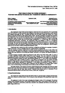
The experiments were performed in a wave flume with dimensions 15 m (length) x 1 m (width) x 0.54 m (height). Figure 1 illustrates the equipment used in the laboratory setup. Three different porous test models which were each 0.90 m long, 0.90 m wide and 0.20 m high were constructed. The tested models shaped similar to that used by Ting et al (2004), consisted of square cross-section of different sizes making up a rectangular framework structure. The test models were made from steel. A typical test model used in the experiments is shown in Figure 2. The test models were fabricated with three different porosities of 0.4, 0.6 and 0.8.
Wave b
Wave k
Model
Wave absorber with 1:10 sloping
Wave b
ds = 0.10 m d = 0.30
7m
0.90 m
1m
0.61 m 5.74 m
Figure 1: A simple sketch of the experimental setup
Malaysian Journal of Civil Engineering 19(1) : 17-25 (2007)
20
Table 1: Physical dimensions of individual test model unit Model Unit Type
Porosity, n
Gap size, a (cm)
0.4 0.6 0.8
2.4 5.8 17.8
1 2 3
The porosity, n is defined as the volume of empty space in a model unit divided by the total geometrical volume of the test model unit. The physical dimensions of individual test model units are presented in Table 1. A solid test model unit with similar outer dimensions as the porous units (90 cm length X 90 cm width X 20 cm height) was also used in the tests. The still water depth, d was maintained at 0.30 m in the test runs so as to maintain a non-breaking wave condition. Each set of test was subjected to regular waves covering a range of wave periods from 0.71 sec to 1.03 sec. These values were adopted due to the limitation provided by the wave generator and the flume used in the test series.
20 cm
12.4 cm 90 cm
90 cm
a
a
Steel size framework 3.8 x 3.8 cm
a)
Sketched dimensions of the test model rectangular steel
b) The fabricated framework used in the test series
Figure 2: A typical test model with a porosity of 0.6
Table 2 illustrates the incident wave conditions used in the experiments. Ten sets of wave period ranging from 0.71 s to 1.03 s were used. Ten different wave heights which could be generated by the paddle were imposed on the three porous test models in the test series. A total of 80 runs were carried out in the test series altogether. The conventional method as used by Dean and Dalrymple (1991) has been adopted to separate the measured wave train into its incident and reflected wave components. The mean transmitted wave height was determined by taking an average of at least 10 wave heights in the wave train.
Malaysian Journal of Civil Engineering 19(1) : 17-25 (2007)
21
Table 2 : Typical incident wave conditions generated using the n= 0.4 model unit Time Period T (s)
Wavelength L (m)
kd
Wave Height HI (cm)
Relative Wave Steepness HI/L
0.706 0.734 0.758 0.789 0.818 0.855 0.896 0.937 0.985 1.037
0.767 0.824 0.873 0.938 0.998 1.075 1.160 1.244 1.342 1.448
2.458 2.288 2.158 2.010 1.889 1.754 1.625 1.515 1.404 1.302
4.1209 4.4525 4.7984 5.838 6.1182 6.7926 6.9015 5.9646 6.3700 6.6788
0.0537 0.0540 0.0549 0.0622 0.0613 0.0632 0.0595 0.0479 0.0474 0.0461
3.0
Experimental Results and Discussion
There were three main parameters used to describe the characteristics of wave attenuation by the test models. These were: (i)
reflection coefficient, KR which is expressed by
KR = HR
(1)
HI
where HR is reflected wave height (m) and HI is incident wave height (m) (ii)
transmission coefficient, KT as given by :
KT = H T
(2)
HI
where HT is transmitted wave height (m) and HI is incident wave height (m)
(iii) wave energy loss, EL (or KL as used herein) can be determined from :
(
EL = K L = 1 − KT − K R 2
2
)
1
2
PP
(3)
Figure 3 illustrates a plot of the transmission coefficient, KT against the dimensionless parameter kd (where k is the wave number and d is the water depth) for the three model units whose porosities were 0.4, 0.6 and 0.8 at the relative depth of submergence, ds/d which equals 0.30. It is demonstrated that wave attenuation is not
Malaysian Journal of Civil Engineering 19(1) : 17-25 (2007)
22
significantly affected when the porosities of the submerged breakwater increased. KT reached 0.71, when the porosity of the model was 0.8 and a kd at 1.40. Most KT values at n = 0.80 varied between 0.53 to 0.71. When the porosity reduced to 0.6, KT varied around 0.44 to 0.60. The KT values ranged from 0.36 to 0.57 when the porosity decreased further to 0.4. In all test cases, KT is lowest when kd varied between 1.90 to 2.50. KT was observed to increase with decreasing kd which implied that the longer the waves (that is, the lower the kd values), the larger the transmission coefficient. Within the limits of the test results it has been illustrated that the more porous the test models, the more capable they were to attenuate longer waves. The presence of the porous feature of the model has allowed the longer wave to penetrate the structure and to lose its energy before being transmitted to the leeside to result in a higher KT value. KT vs kd 1.00 0.80
K
0.60 0.40 0.20 0.00 1.20
1.40
1.60
1.80
2.00
2.20
2.40
2.60
kd Porosity = 0.8 Porosity = 0.6 Porosity = 0.4
Figure 3. Wave transmission coefficients over the submerged breakwater at various porosities
Figure 4 shows a plot of the reflection coefficient, KR versus kd at ds/d = 0.3. The results illustrated that model porosity is not sufficiently significant to influence the KR value. KR is highest at a value of about 0.31 when the porosity of the model is 0.4 and lowest at a value of 0.01 when the porosity increased to 0.8. It was also obvious from Figure 4 that for the tested model, the reflection coefficient was unlikely to reduce below 0.01. It was also obvious from both Figures 3 and 4 that less porous models corresponded to a larger KR but smaller KT and vice versa.
Malaysian Journal of Civil Engineering 19(1) : 17-25 (2007)
23
KR vs kd 1.00 0.80
KR
0.60 0.40 0.20 0.00 1.20
1.40
1.60
1.80
2.00
2.20
2.40
2.60
kd Porosity = 0.8 Porosity = 0.6 Porosity = 0.4
Figure 4. Wave reflection coefficients due to waves traveling over submerged breakwater with various porosities and at a relative depth of submergence, ds/d = 0.3
Figure 5 indicates the effect of wave energy loss due to the presence of porous submerged breakwater test models at ds/d = 0.3 in the flow. Generally, it was seen that for the larger porosity test model (n = 0.8), the energy loss or KL value was maintained at about 0.8 and decreased when kd < 2. The KL values varied between 0.80 and 0.90 when the porosity of the test model was 0.6 and was lowest when kd reached a value of about 1.51. K L vs kd 1.00 0.80 K
0.60 L
0.40 0.20 0.00 1.20 1.40 1.60 1.80 2.00 2.20 2.40 2.60 kd Porosity = 0.8 Porosity = 0.6 Porosity = 0.4
Figure 5. Wave loss coefficients due to waves traveling over submerged breakwater with various porosities and at a relative depth of submergence, ds/d = 0.3
Malaysian Journal of Civil Engineering 19(1) : 17-25 (2007)
24
When the porosity of the model was 0.4, KL was highest when 1.75 < kd < 2.16 and the highest value of KL = 0.82 was reached when kd = 1.75. It was observed that models which were less porous tended to dissipate greater wave energy. Energy loss was lesser when the porosity was larger and least for the most porous model (n = 0.80). Also, wave energy loss increased as the model porosity decreased at small kd values but this was not so obvious when the kd values were larger. The longer the wave (i.e. the lower the kd values), the lesser the energy that would be dissipated. Table 3: Comparison of results to illustrate the effects of porosity on KT, KR and KL Results from the present investigations for ds/d = 0.3 Porosity (n)
KT
0.40 0.60 0.80
0.37-0.57 0.44-0.60 0.53-0.71
KR
KL
0.11-0.31 0.79-0.92 0.06-0.27 0.77-0.89 0.01-0.24 0.71-0.83
Results from Ting et al (2004) for ds/d = 0.2 Porosity (n)
KT
KR
KL
0.421 0.588 0.805
0.50-0.76 0.63-0.80 0.73-0.84
0.05-0.30 0.01-0.19 0.02-0.10
0.63-0.83 0.59-0.77 0.53-0.68
As shown in Table 3, the present results generally show similar trend with those found by Ting et al (2004).. The results showed that there existed an increase in KT when the porosity values increased. This meant that as the test models were more porous the more capable they were to transmit waves. The values of KR and KL decrease with an increase in the porosity value. 4.0
Conclusions
This study addressed how variation of porosity of a submerged porous obstacle, typifying a submerged permeable breakwater, affects non-breaking wave transformations. The important findings of the laboratory investigations are as follows : a) The increase in porosity slightly affected the attenuation of transmitted waves. The highest KT of about 0.70 was observed when the porosity of the model was 0.8. The KT values reduced with smaller porosity values. b) The reflection coefficient, KR decreases with increasing porosity with the highest value of 0.31 observed when the porosity of the model was 0.4 and c) lowest at around 0.01 when the porosity was 0.8. d) The porous test models were relatively less effective in dissipating wave energy against longer waves (that is, lower kd values) compared to shorter wave (that is, high kd values).
Malaysian Journal of Civil Engineering 19(1) : 17-25 (2007)
25
e) Results from the present investigations also showed that the values of the wave energy loss, KL decrease with an increase in the porosity value and vice versa. Acknowledgement The authors are indebted to the Coastal & Offshore Engineering Institute of Universiti Teknologi Malaysia for providing financial funding, technical staff and laboratory facilities to ensure the successful completion of the above project. References Abdul Wahab, M.A. (2006) Laboratory Investigations on the Performance of Porous Submerged Breakwater, B. Civ. Eng. Thesis, Faculty of Civil Engineering, Universiti Teknologi Malaysia. Black, K and Mead, S. (1999) Submerged Structures for Coastal Protection, ASR, Marine and Freshwater Consultants, New Zealand. Dean, R. D. and Dalrymple, R. A. (1991) Water Wave Mechanics for Engineers and Scientists, USA : World Scientific. Ting, C. L., Lin, M. C., Cheng, C. Y. (2004) Porosity effect on non-breaking surface waves over permeable submerged breakwaters. Coastal Engineering, 50: 213-224. Huang, C. J., Chang, H. H., Hwung, H. H. (2003) Structural permeability effects on the interaction of a solitary wave and a submerged breakwater. Coastal Engineering, 40: 1– 24. Dattatri, J., Raman, H. and Shankar, J.N. (1978) Performance characteristics of submerged breakwaters. Proceedings of the 16th Inernational. Conference in Coastal Engineering, ASCE, Hamburg, Germany, pp. 2153–2171. Gu, Z., Wang, H. (1991) Gravity waves over porous bottoms. Coastal Engineering, 15; 497– 524 Pilarczyk K. W. (2003) Design of low-crested (submerged) structures. Proceedings of the 6th International Conference on Coastal and Port Engineering in Developing Countries, Colombo, Sri Lanka, pp 1-19 Losada, I.J., Losada, M.A. and Martin, F.L. (1995) Experimental study of wave induced flow in porous structure. Coastal Engineering, 26: 77-98. Sollitt, C.K. and Cross, RH (1972) Wave transmission through permeable breakwaters. Proceedings of the 13th International Conference in Coastal Engineering, pp 1827-1846.