PUMP BEAM SHAPER DEVICE - PRELIMINARY RESULTS Samanta C. T. dos Reis*, Marcelo G. Destro, Nicolau A. S. Rodrigues and Carlos Schwab
*Instituto Tecnológico de Aeronáutica - São José dos Campos, SP, Brazil Instituto de Estudos Avançados - São José dos Campos, SP, Brazil
[email protected]
Abstract We developed a pump beam shaper device destined to improve the spatial overlap between the pump and the signal beams in a dye laser amplifier transversally pumped by a copper laser. The device uses a closely spaced mirror pair for reshaping and homogenizing the pump beam. This paper describes the results of preliminary experiments performed by shaping the beam of an HeNe laser.
Introduction One of the main objectives of developing lasers and laser amplifiers at IEAv-CTA is giving support to the atomic vapor laser isotope separation program [1]. In this uranium enrichment method, a tunable dye laser is used to selectively excite and ionize the fissile isotope of uranium. This program demands, therefore, the development of dye laser power amplification stages [2- 4]. In high-gain systems, particularly under strong pumping conditions, considerations about amplified spontaneous emission (ASE) are of fundamental importance. This is particularly true for dye laser amplifiers transversally pumped by copper vapor lasers, where one must to optimize and control the spectral characteristics of operation of the dye laser amplifier system [3-5]. The ASE resultant at the amplifier stage increases the dye laser spectral linewidth decreasing, in consequence, the isotope separation process selectivity [1]. Transversely pumping of the dye laser amplifier by copper vapor laser demands modification of the copper beam shape. In this system the pump beam shape and size must matched dye signal beam for efficient amplification and low ASE. Generally, this is done by focusing the pump beam at the dye cell amplifier through a cylindrical lens [4,1,6]. However, the “soft” edges of the focused beam may mean that a significant fraction of the pump light is poorly converted to amplified signal, or it generates ASE, or the pump intensity at the focus is too strongly peaked to produce the desired intensity uniformity in the amplified signal beam [6]. Efficient utilization of the copper vapor laser pump with low ASE also requires the shape and size of the pump beam well matched to that of the dye beam in the generally rectangular overlap volume. The dimension parallel to the flow direction (see references [4] and [6]) is somewhat more critical than that in the signal beam direction [6]. We have, therefore, built a device, similar to that proposed in reference [6], using two closely-spaced, nearly parallel mirrors that, by multiple reflections, can reshape and homogenize the beam at the output gap between the mirrors. In this work we show and discus qualitatively the preliminaries results obtained with the investigation of the operation characteristic of this device using an expanded HeNe laser beam.
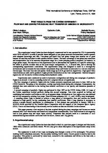
Experimental Setup The principle of operation of a beam shaper device, built using two closely-spaced nearly parallel mirrors, used to reshape and homogenize a beam can be understood by using the schematic diagram shown in Figure 1. An optical element such as a lens set collimates or focuses the incoming circular laser beam to a line focus at the input gap of the mirror pair. While the central segment of the beam passes between the mirror pair without reflection, outer segments will reflect one or more times as the beam expands beyond the line focus. Each segment, or order, exits the mirror pair at a deviation angle which increases with the number of reflections. The various orders of the laser light exiting the mirror-pair are incident on an optical device which forms an image of the output gap of the mirror-pair in the plane image. The resulting image has a generally rectangular shape defined by the edges of the output gap of the mirror-pair along the long dimensions and by the profile of the incoming laser beam [6].
Figure 1: Schematic representation of the mirror-pair used to homogenize and reshape a circular laser beam [6]. The diagram of our experimental apparatus is shown in Figure 2. The HeNe laser beam was expanded by lens L1 and L2 in order to obtain a 10 mm beam diameter. This beam impinges on the input gap of the mirror-pair that has approximately 7.2 mm height. Two aluminum mirrors having 100 x 20 mm dimension were used as a closely spaced mirror pair for reshaping and homogenizing lasers beam. The output gap of this beam shaper device was adjusted to approximately 0,8 mm. The various orders reflected beams impinge on an optical image system built by L3 and L4 lens that images the output gap on a Waltec CCD camera, model M-39244. The CCD signal is analyzed by a Spiricon Advanced Laser Beam Analyzer, Model LBA-100A.
L1
L3 L4
Mirror-Pair HeNe Laser
L2
CCD
f
f
LBA
Figure 2: Experimental apparatus: L1 and L2 are the beam expander lens; L3 and L4 are the optical image lens; CCD is the CCD camera and LBA is the laser beam analyzer
Results and Discussions The summary of preliminary qualitative experimental results is shown in Figure 3. The experimental setup and the mirror-pair detail are shown in Figure 3 (a) and (b). By impinging a 10 mm diameter expanded HeNe laser beam at the input gap of the mirror-pair, with 7.2 mm height, we obtain at the output gap, with 0,8 mm height, 9 orders due to multiple reflections between the mirror pair, in accordance with literature results [6]. In Figure 3 (c) we can see only 7-orders. Due the saturation of the digital camera used but we can not see the two lower intensity orders in this photography, but they are seen with unaided eyes. Figure 3(d) shows the output gap image on the screen plane. When the screen plane is moved we can see the overlap of various orders. The central distribution intensity profile is shown in Figure 3 (e). This profile was obtained by putting the output gap mirror at the image lens system focal position, and the light of the central order magnified impinges on a CCD camera of Spiricon Laser Beam Analyzer. The overlap of various orders on the output gap image plane is shown in Figure 3 (f). The output gap image distribution intensity profile was obtained by using an optical image lens system with focal length of 75 mm and aperture of 75 mm diameter. This system was positioned to magnify the image of the output gap by a factor of approximately 2.6, i.e., lens object distance of ~ 110 mm and lens image distance of ~ 280 mm. As ones can see in Figure 3 (f) a step distribution intensity profile was obtained on image plane, in spite of the ripple that appears on it. This ripple may be due the N-order overlap interference effect. However, more detailed studies of this and other effect are subject of future works.
(a)
(b)
(c)
(d)
(e)
(f)
Figure 3: Summary of preliminary qualitatively experimental results. a) experimental setup; b) mirror-pair detail; c) N-orders of output beam due to multiple reflections inside the mirror-pair; d) image of the mirror-pair output gap; e) central order distribution intensity profile and f) image distribution intensity profile of the mirror-pair output gap.
Conclusions We have obtained the preliminary qualitative experimental results from a beam shaper device that uses a closely spaced mirror pair for reshaping and homogenizing laser beams. Multiple reflections of the laser beam inside of the mirror pair homogenizes the beam in the output gap and several orders observed. Imaging the output gap on a plane image produces a nearly rectangular distribution intensity profile. Using a HeNe laser interference fringes due the overlap of different orders on the image plane have been observed. However, more detailed studies of this and other effects are subject of future works. Although no quantitative analysis nor detailed studies have been performed, these preliminary results are important because these show that this device can work well to shape and homogenize the laser beam. Therefore, this indicates that our initial purpose to use it to improve the spatial overlap of a copper laser pump beam with the signal beam in dye laser amplifier stages, of the isotopes separation process, is feasible.
Acknowledgements The authors thank the Fundação de Amparo à Pesquisa do Estado de São Paulo – FAPESP that has partially supported this work. We also thank the colleagues that somehow have encouraged and helped the elaboration of this paper.
References [1] SCHWAB, Carlos, DAMIÃO, Alvaro J., SILVEIRA, Carlos A. B., NERI, José W., DESTRO, Marcelo Geraldo, RODRIGUES, Nicolau A. S., RIVA, Rudimar, MIRAGE, Armando. Laser techniques applied to isotope separation of uranium. Progress In Nuclear Energy Special Issue Reviews of the X ENFIR III Enam Brazilian Joint Nuclear Conference 1997, v.33 N 1, p.217-264, 1998. [2] DESTRO, Marcelo G., “Uranium Metal Vapor Laser Spectroscopy”, Doctor These, ITA, 1993, (in Portuguese). [3] DESTRO, Marcelo Geraldo, NERI, José W., “Small-signal gain and saturation intensity measurements in dye laser amplifier stages”, Relatório de Pesquisa IEAv-RP031/90, 1990 (in Portuguese). [4] DESTRO, Marcelo Geraldo, NERI, José W., “Small-signal gain and saturation intensity in dye laser amplifiers”, Applied Optics, 31-33, 7007-7011, 1992 (in English). [5] GANIEL, U., HARDY, A., NEWMANN, G., and TREVES, D., “Amplified spontaneous emission and signal amplification in dye laser systems”, IEEE J. Quantum Electron. QE-11, 881-892 (1975). [6] BASS, Isaac L., “Closely spaced mirror pair for reshaping and homogenizing pump beams in laser amplifiers”, SPIE, Vol. 1869, 128-135, 0-8194-1096-9/1993.