ment Corporation and NCR corporation for their gen- erous support of our research. We also wish to ack- nowledge our colleagues in the Aquarius Research ...
Exploiting
Horizontal
and Vertical
Concurrency Wen-mu
via the
HPSm Microprocessor
W. Hwu
Coordinated Science I.aboratory University of Illinois Urbana. II. 61 %;I Yale N. Pntt
Computer Science Division University of California Berkeley, CA 94720 ABSTRACT
microoperations defined in the explicit format bandwidth while
HP&n is B single-chip micraarchitecture designed and implemented at the University of California to achieve high performance. The approach is to exploit both vertical and her. izontal concurrency in the microarchitecture. Experimenta have been conducted to demonstrate the effectiveness of HPSm 8s compared to B popular single-chip microarchitecture, the Berkeley RISC/SPUR. Evaluations have been done with both control intensive and floating point intensive benchmarks. For both types of benchmarks, we show that the HPSm microarchitecture achieves significant speedup over the RISC/SPUR microarchitecture implemented with the same fabrication technology.
may start/finish execution before others same instruction. We use the parallel in order to provide high instruction keeping the decoding logic small.
There are twelve access ports to the Register Alias Table: six read ports and three reservation ports support the merging of three microoperations every cycle; three distribution ports deliver three execution results every cycle. Three node tables provide the capability to submit three microoperations for execution every cycle There are two Arithmetic and Logic C‘nits, one data memory access interface, and one floating-point processor The repair mechanism keeps three machine states, the minimum necessary to properly recover from all possible exceptions. When exceptions occur, the machine state can be recovered to an instruction boundary before the exception points. This facilitates proper exception handling and execution resumption When an incorrect
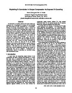
I. Introduction 1.1. HPSm HPSm is a single-chip VLSI implementation of the HPS model of execution [1,21. An introduction to HPS, including our rationale as to why it is effective for high performance implementation of very dissimilar ISP architectures is contained in [31. Figure 1 illustrates the generic block diagram of HPS. HPSm uses a fixed instruction format to reduce the instruction decoding logic. Each instruction explicitly defines three microoperations; this provides the concurrency of fetching three microoperations every cycle. The instruction format looks like those of the VLIW machines 141 but the underlying execution model is very different. Unlike the VLIW machines, the microoperations defined in the same instruction do not execute in Due to data dependencies, some of the lock-step.
Permission to copy without fee all or part of this material is granted provided that the copies are not made or distributed for direct commercial advantage, the ACM copyright notice and the title of the publication and its date appear, and notice is given that copying is by permission of the Association for Computing Machinery. To copy otherwise, or to republish, requires a fee and/or specfic permission. 0 1987 ACM
089791”250-O/87/0012/0154
Figure
$1.50 154
1. HPS Generic Block Diagram
branch prediction occurs, the machine state is recovered to the point just before the branch instruction and then the machine resumes execution along the correct branch This feature eliminates the programming path. difficulties experienced by users of out-of-order execution machines such as the IBM/360 Model 91 15,61. The CPU microarchitecture is implemented with the HP 1.6um CMOS 208pin technology on a 10.5mm by 10.5mm chip. The projected cycle time is 80ns with a four-phase clocking scheme. Each microoperation spends at least four cycles (sixteen clock phases) in the microengine. In the presence of dependencies, the microoperations tend to spend more cycles in the microengine. 1.2.
Horizontal
and
Vertical
Concurrency
Horizontal concurrency is the concurrency exploited by horizontal microcode. At the architecture level, horizontal concurrency exists if microoperations in the same instruction can execute in the same cycle. At the microarchitecture level, horizontal concurrency exits if microoperations can be simultaneously executed at the same pipeline stage.
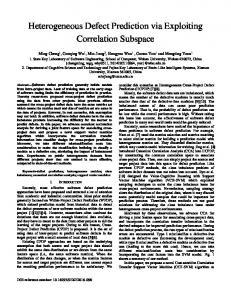
Figure 2. The HPSm Data Path to support twelve accesses each cycle, maintains the dependency information for each register entry, provides the source operand values (if they are ready) and the tag of the operation producing the source operand values, removes data output dependencies, and repairs the contents of each register entry if necessary.
Vertical concurrency is defined as the concurrency exploited by pipelining. At the architecture level, vertical concurrency exists if microoperations in different instructions can execute in the same cycle. At the microarchitecture level, vertical concurrency exists if microoperations can be simultaneously executed at different pipeline stages. 1.3.
Organization
of This
The Node Tables buffer the microoperations waiting for data/control dependencies, enforce data flow depenschedule dencies, remove data antidependencies, microoperations, and discard appropriate operations during repair.
Paper
The function units perform integer arithmetic logic operations, branch prediction verifications, memory accesses, and coprocessor data transfers.
The paper is organized in four sections. Section 2 describes the microarchitecture of the HPSm chip, Section 3 reports the measurements taken for several benchmarks, compares them to those obtained for the Berkeley RISC/SPUR, and analyzes the results of the comparison. Section 4 offers some concluding remarks. 2. The 2.1.
HPSm
Major
Single-Chip
2.2.
Microarchitecture
The HPSm microarchitecture consists of six major components: the instruction unit (IU), the Register Alias TabIe (RAT), the Node Tables (NT’s), the function units (FU’s), the Floating Point Unit (FPU), and the memory system. The first four major components fit on a single chip 1.6 urn CMOS implementation (see Figure 2).
Clocks then travels through eleven inverting delay stages to generate twelve (including itself) clock signals equally distributed in the leading half cycle. These clock signals are separated from their immediate neighbors by one twelfth of the half cycle time. We will refer to the k - lth delayed clock signal as clockr. A stage is defined as the delay between the immediate neighbors of these clock signals, which is 3 ns in our prototype design.
The instruction unit (1) determines the next instruction fetch address, (2) fetches instructions, (3) executes unconditional branch and jump instructions, (4) performs branch prediction, (5) generates save/repair signals, and (6) assigns tags to instructions. Alias Table provides
Scheme.
We use a twelve-stage version of the PLL-based clock generator by Jeong 171 to provide all the clock/control signals. A reference signal with the desired cycle time and 50% duty cycle is fed into a Phase Lock Loop to generate clocks (see Figure 3). In the prototype design, our clock frequency is 72 ns.
Components
The Register
Clocking
and data
Four pulses (each two stages in pulse width) are generated at the rising edge of clocks, the rising edge of clock?, the falling edge of clockl, and the falling edge of
high bandwidth
155
cycles in the pipeline and these four cycles are further divided into eight stages (separated by the pipe line latches) as described below.
“^‘-Ell PLL
clock
clocks
1 through
1
12
.__
combinational
1111 pulases
sta.ge 1
This stage comprises the entire first cycle during which the fetch PC is determined by the IU (instruction unit). This involves i.ncrementing the last fetch PC, adding an offset to the last fetch PC, and selecting among the six potential PC’s according to the conditions produced by the instruction decoding, data path execution, and external interrupts.
stage 2
This stage consists of phases one, two, and three of the second cycle. At stage 2, fetch PC is transmitted off-chip to the instruction cache and used to access the data and tag stores of the instruction cache.
stage 3
This stage is phase four of the second cycle. At stage 3, the first part of the fetched instruction (the source addressing modes and register numbers) are transmitted onchip from the instruction cache.
stage 4
This stage is phase one of the third cycle. The first source operands of all three fetched microoperations are fetched from the RAT. The signals on the buses will be latched into the 0th entry of the three NT’s at the following pulse.
stage 5
This stage is phase two of the third cycle. The second source operands of all three fetched microoperations are fetched from the RAT. The signals on the buses will be l.atched into the 0th entry of the three NT’s
_ .,
^
logic
,“3
1. 2, 3, 4
control
signals
Figure 3. The Clock Generator I. The rising edges of these four pulses define the beginning of the four phases,
clock
Other
control
signals
are generated
clock I through
clock 12 as appropriate.
2.3. Pipeline
Timing
by combining
2.3.1. Core Timing The core timing of a pipeline is defined as the minimal signal propagation timing for each microoperation. The core timing is the ideal timing for a microoperation without events such as IU stalls, delays due to data dependencies, and multiple cycle FU evaluation. line.
Figure 4 shows the core timing of the HP&n pipeEach HPSm microoperation spends at least four
Figure 4. Core Timing,
156
the HPSm Pipeline
None of the subsequent
at the following pulse. The second part of the fetched instruction (opcodes and output operand specifiers) are transmitted on-chip from the instruction cache at this stage, The IU stall signal which was evaluated during stages 3 and 4 is transmitted on-chip at this stage. stage 6
stage 7
stage 8
This stage is phase three of the third cycle. The input operands of the fetched microoperations, if they are not ready, will monitor the tag, ready, and value buses to receive the operand values.
arefetched.
The double pending prediction stall occurs if a conditional branch microoperation is fetched before the prediction for the previous one is verified. The instruction containing the second branch is forced to re-execute the third cycle of the core timing until the branch prediction pending signal clears. None of the subsequent instructions are fetched.
This stage is phase four of the third cycle. If both input operands of the incoming microoperations are ready, the microoperation becomes eligible for execution. If there is no older eligible microoperation in the same NT, the microoperation is fetched from the NT and submitted for execution.
The fetch hold stall occurs when the instruction cache and/or translation buffer misses. The microoperations being fetched are forced to re-execute the third cycle of the core timing until the instruction cache and/or translation buffer miss signal clears. None of the subsequent instructions are fetched.
This stage consists of phases one, two, and three of cycle four. The FU evaluates the execution result and put the result on the buses.
2.3.2. Extended
instructions
The node table overflow stall occurs if the 0th entry of at least one NT contains a valid microoperation when the new microoperations need to be latched into the NT’s (at stage 5). The microoperations within the fetched instruction are prevented from being latched into the NT’s and from reserving the output RAT entries. They continue retrying their third cycle of the core timing until the node table overflow signal clears. None of the subsequent instructions are fetched.
Data/control Dependency Delays. If at least one of the input operands is not ready at the time a microoperation reached stage 6, the microoperation is forced to re-execute stage 6 until both input operands are ready. This means that the delayed microoperation stays in an NT and monitors the tag, the ready, and the value bus in order to receive the input operand(s). There can be several microoperations waiting at stage 6 in the NT’s at the same time. The microengine continues issuing the following instructions.
Timing
A microoperation can spend more than four cycles in the HPSm pipeline due to events which prevent the microoperation from advancing immediately from one stage to the next, for example: Instruction Unit Stalls. The instruction unit can stall due to any of the following: instruction fetch hold (instruction cache misses or instruction translation buffer misses), jump target pending (the target address of a jump operation is still being evaluated in the data path), node table ouerfloul (at least one of the node tables are filled with microoperations waiting for their input operands), or double pending branch prediction (a conditional branch is fetched while the previous branch prediction is yet to be verified).
If there is more than one FU conflict delays. microoperation eligible for execution at the same time in the same NT, only the one which entered the NT first is submitted. The others must wait until they become the oldest in that NT, at which time they re-execute stage ‘7. The microengine continues to issue subsequent instructions. Multiple-cycle FU evaluation. If the microoperation takes more than one cycle for the appropriate FU to evaluate, it requires additional cycles to complete stage 3. Since all the multiple-cycle FU’s are pipelined in the HPSm microarchitecture, This event does not cause any blocking to the following microoperations which are eligible for execution.
The jump target pending stall occurs when the next fetch address can not be determined at the moment a jump operation is executed. In the HPSm architecture, control transfer to an arbitrary program location is performed by having a microoperation load register 31 with the target address and then execute a jump microoperation. If the microoperation that loads register 31 has not finished execution when the jump microoperation is fetched, all the microoperations within the fetched instruction are prevented from being latched into the NT’s and from reserving the output RAT entries, Instead, they continue retrying their third cycle of the core timing until the jump target pending signal clears.
3. The Experiments Experiments have been the effectiveness of HPSm single-chip microarchitecture, Evaluations have been done
157
conducted to demonstrate as compared to a popular the Berkeley RISC/SPUR. with both control intensive
A microoperation which is whose destination register does can be migrated to the previous usually results in greater microoperations from adjacent loop.
and floating point intensive benchmarks. For both type of benchmarks, the HYPSm microarchitecture achieves significant speedup over the Berkeley RISC/SPUR implemented with the same fabrication technology. Due to limited manpower, our compiler is not yet robust enough to translate very large programs. Consequently, we have chosen several small benchmarks which demonstrate both the strengths and the weaknesses of the HPSm microarchitecture. For integer environments, we use control-intensive Berkele,y RISC benchmarks (i.e., Towers of Hanoi and Ackerman’s Function) to show how HPSm handles these challenges to its pipelined microarchitecture. We also use more typical Berkeley RISC benchmarks (Quicksort, string match, linked list insertion, and bit matrix manipulation) to demonstrate how these computations can benefit from the horizontal concurrency of HPSm. For floating-point environments, we use parallel benchmarks to show the effectiveness of HPSm in exploiting parallelism. We also use the sequential benchmarks from the Livermore Loops to show the graceful HPSm performance degradation in the presence of sequentiality.
not a memory write and not contain C variables iteration of a loop. This overlap between the iterations of the same
Lazy Scheduling. This optimization is done to all basic blocks after the greedy scheduling and the interiteration scheduling are done. The microoperations are delayed as much as allowed by the available slots and the dependencies. For each microoperation, the search begins from the original instruction it was placed in, and continues until at least one of the following two condi. tions occur: (1) Another microoperation depending on that microoperation is found (further delaying the microoperation can cause delay to the dependent microoperation), or (2) The last instruction been reached.
generated
for the loop has
When the search ends, the algorithm tries to find an available slot which is as late as permitted by the dependent instruction and which is later than the original If such a slot is found, the microoperation is instruction. migrated into the new slot. This usually results in denser code with the same execution time as the original code.
3.1. Code Generation All the benchmarks used in our performance measurement are written in the C programming language. Shebanow et. al. 181 have developed a compiler front-end which generates an intermediate form, Perfect lnterWe have mediate Form, for each source program. developed a code generator which generates the HPSm microoperations from the PIF and then uses all four techniques shown below to schedule these microoperations into actual HPSm instructions.
Cleaning Up. If a microoperation is the only one in its corresponding instruction and if there is an eligible slot in the neighboring instruction, the microoperation is moved to create an empty instruction. The empty instruction is then removed.
Each instruction contains Greedy Scheduling. three slots. The first slot accommodates a memory microoperation. The second slot accommodates either a branch prediction verification microoperation or an integer ALU microoperation. The third slot accommodates either a floating point ALU microoperation or an integer ALU microoperation.
3.2. The Simulator The simulator is written in C. The pipeline registers and signal lines are simulated with C static variables and the switching of these registers and lines are performed with C statements. The CPU pipeline is simulated at the register transfer level in which at each clock edge, some pipeline registers and/or latches change state.
Greedy scheduling is performed within each basic block. For each microoperation, its dependencies on all other microoperations in the same basic block are identified and used to determine the earliest instruction that the microoperation can be placed in. The algorithm then starts from that earliest instruction to find an empty slot which can accommodate the microoperation.
The simulator can run in interactive mode or in batch mode. In interactive mode, a debugging environment is provided around the simulator to support single phase execution, single cycle execution, breakpointing, examining pipeline registers/latches, examining memory the pipeline register/latch states, contents, changing changing memory contents, etc. In batch mode, the simulator collects performance data.
Code scheduling Inter-Iteration Scheduling. across conditional branch boundaries is expensive. We perform limited scheduling across conditional branch boundaries by migrating microoperations between adjacent iterations of the inner loop. By inner loop, we mean a loop containing no other loops or conditional branches.
3.3. The Berkeley
RISC Benchmark
Six of the Berkeley
158
RISC
Measurements
benchmarks
(Tower
of
Hanoi , Ackerman’s function, Quicksort, string match, linked list insertion, and bit matrix manipulation) were executed on both the HPSm simulator and the Berkeley RISC II simulator to obtain the cycle count. To compare the performance, we have to have the cycle time for both chips implemented with the same technology. The RISC II chip was implemented with 3um NMOS single metal layer technology and achieved a cycle time of 330 ns 191. We would like to estimate its cycle time if it were implemented in the same technology as HPSm, a 1.6 urn CMOS double metal layer technology. This is done by using the Berkeley SPUR cycle time as the estimated new RISC II cycle time. Our reasoning is that the microarchitecture of SPUR is very similar to that of RISC II and that SPUR is implemented in the same technology as HPSm.
BenchH
0.4SK
HPSm
0.18K
ratio
2.5
RISC II
HPSm
45us
14us
1 ratio
3.2
Comparison*
That is, we perform about 2.2 HPSm microengine. microoperations (each of which is roughly equivalent to a RISC II instruction) per cycle while the RISC performs less than one instruction per cycle (one per cycle if there is no data memory access and one every two cycles if there is a data memory access). Even though the register window mechanism screens out much of the procedure calling overhead and most of these benchmarks are procedure call intensive, the HPSm still managed to achieve smaller cycle counts due to its horizontal concurrency. Table 1 also shows the execution time ratio between a hypothetical 1.6um CMOS RISC II chip and the 1.6um CMOS HPSm chip. Less global control, more extensive pipelining, and faster register file accesses in HPSm contributed to the faster cycle time of HPSm. The execution time ratio lies between 1.4 to 4.4 in favor of the HPSm chip. The typical ratio is about 2 times in favor of the HPSm chip.
The performance comparison is summarized in table 1. It takes RISC II from 1.1 to 3.6 times more cycles to execute the same benchmarks than it does HPSm. The Towers of Hanoi benchmark is the most favorable to RISC II because all this benchmark does is shallow recursive calls/returns and the register window in RISC II screened out almost all the register save/restore instructions. Ackerman’s function benchmark is least favorable to RISC II because all it does is deep recursive calls/returns and the register window in RISC II overflows (and underflows) continually.
The Berkeley RISC benchmark experiments demonstrate that a microengine with rich horizontal concurrency can do very well even when executing control intensive toy benchmarks (cycle count). The short cycle due to pipelining and distributed control secures the advantage of horizontal concurrency. 3.4. The Livermore
Loop Measurements
The Livermore Loops provide kernels of scientific computation which are characterized by simple control structure and significant portions of number crunching They are very different from the Berkeley instructions. RISC benchmarks where control and integer instructions prevail. Seven of the Livermore Loops were measured on the HPSm simulator. The comparison is not made with RISC II because there is no FPU chip designed for RISC II and it would be unfair to compare the performance of HPSm having an FPU with that of RISC II which implements floating-point operations in software.
Benchmark F results in a ratio relatively close to 1 because it causes a very poor instruction cache hit ratio. The HPSm simulator does accounts for the instruction cache miss penalties but the RISC II simulator does not. If we subtracted the instruction cache miss penalty from the HPSm cycle count, the ratio would be close to 1.7. The mare typical cycle ratios vary from 1.6 to 2.5 times in favor of HPSm. We have to emphasize that the performance improvements presented thus far are all due to the horizontal concurrency available in the HPSm time for 72ns, the of 100 ns although
1 RISC 11
Table 1. HPSm vs. RISC II Performance
The reason we were not able to compare the SPUR 1101 chip with the HPSm chip is because we have been told that the SPUR C compiler is not yet available. Due to the similarity of the RISC II and the SPUR microarchitectures, we expect that the number of cycles it takes to execute these benchmarks on SPUR would be at least as large as the number of cycles it takes to execute these benchmarks on RISC II. Therefore, a more than fair estimate for a RISC II chip implemented with the same technology as HPSm is to use the cycle count from RISC II and the cycle time from SPUR. This is what we have used as the basis of our comparison with HPSm.
*The cycle operate at cycle time cycle time,
time
cycle count Benchmark
Unfortunately,
HPSm is assumed to be 801~. Even though the CPU is designed to floating-point chip we plan to use operates at 801~. We have chosen a for SPUR since we have been told [ill that they are targeting for that their officially announced cycle time is 150 ns.
159
we can not compare the HPSm simu-
benchmark benchmark
2 3
The HPSm best performance ranges from 2.2 MFLOPS to 6.7 MFLOPS. Livermore Loops 2 and 7 are highly parallel with a high ratio of floating point ALU operations to memory accesses. This results in a high M’FLOPS count, Livermore Loops 5 and 6 are highly sequential with every floating point ALU operation depending on the previous one, which results in a LOW execution ra.te for both the FPU and the CPU. Livermore Loop 4 has a low ratio of floating point ALU operations to rnemory accesses, which results in a high CPU execution rate but a low FPU execution rate.
inner product, five elements per iteration inner product, one element per iteration banded linear equations tri-diagonal elimination, below diagonal tri-diagonal elimination, above diagonal
Table 2. The Livermore
Loops used in the measurement.
lated results with simulated results for SPUR, since we have been told that the SPUR C compiler is not yet available to allow performance measurement/estimation based on compiler generated code. Therefore, we have used an optimistic approach to estimate the performance of SPUR executing these Livermore Loops. The estrmatlon is done by using the sum of the execution times of all the floating-point operations as the loop execution time. Summing the execution times for all the individual operations is justified by the sequential execution model of the SPUR FPU. This is optimistic because, in so doing, we ignore the time it takes to execute the CPU operations and the CPU-FPU synchronizing operations in SPUR, assuming that they can be entirely overlapped with the FPU execution.
The best ratio between the HPSm execution cycle count and the SPUR estimated cycle count is shown in table 4. The execution cycle count ratio ranges from 1.1 to 2.5 in favor of HPSm. The more highly parallel loops give HPS a much better edge due to the overlapped ALU operations. When it comes to serial loops (5 and 6), HPSm does not show much advantage in cycle count because the pipelined floating point ALU is very much under-utilized and the low throughput SPUR floating point ALU can do almost as well.
I
Furthermore, we assume that the SPUR FPU instruction decode and operand fetche can also be overlapped with the floating point ALU evaluation. For example, it takes four cycles to execute a SPUR floating point addition instruction: one cycle to decode and fetch registers and three cycles to compute the floating point addition. We only count the three floating point ALU cycles when estimating the SPUR execution time. Therefore, if a loop contains two floating point addition instructions, we assume that it takes six cycles for SPUR to execute each iteration. The performance of HPSm executing the Livermore Loops is shown in table 3. Two cycle counts are shown for each benchmark. The best cycle count is achieved when the entire floating point data array remains in the cache. The worst cycle count is achieved when the array
Table 4. Performance
I
I
10
2 /
2.5
11.6
id Table 3. HPSm
performanceexecuting
Livermore
Comparison
I time I
between HPSm and SPUR (best)
The performance comparison using the worst situation is presented in table 5. The data cache misses can have greater impact on HPSm performance than on SPUR performance. Therefore, the advantage of HPSm over the estimated SPUR is in general reduced when the data cache miss penalty is introduced. The ratios presented in table 5 are extreme numbers where a cold start is assurned for the data cache.
I
15.25
count
It is worth pointing out that the comparison based on loop 4 may be misleading. This loop has a rather low ratio between floating point ALU operations and other operations. Since we are using an optimistic estimate for SPUR performance, we are ignoring the execution time of all the other operations. With such a low ratio between the floating point ALU and all the others, the execution of the other operations may not overlap very much with t.he ALU evaluation, which would result in the SPUR estimate being far too generous.
is entirely absent from the cache before the loop starts execution. The real cycle count will be somewhere between the two.
4
cycle
Loops
160
Systems 0089.
Command
under
Contract
No. N00039-84-C-
References
[ll Hwu, W.W. and Patt, Y.N., “HPSm, a High Performance Restricted Data Minimal Functionality,”
Table
6
53.5
50.5
1.1
1.4
7
72.5
31.5
2.3
2.9
between
HPSm
5. Performance
4. Concluding
Comparison
Computer
Flow Architecture The
13th
Architecture
Having
International
Symposium
on
Proceedings,
pp. 297-306, Tokyo, Japan, June 1986.
Conference
El Hwu, W.W. and Patt, Y.N., “Design Choices for the HPSm Microprocessor Chip,” Proceedings HICSS, pp. 329-336, Jan. 1987.
of the 20th
Annual and
SPUR
koorst)
[31 Patt, Y.N., Hwu, W., and Shebanow, MC., HPS, A New Microarchitecture: Rationale and Introduction” , Proceedings of the 18th International Microprogramming Workshop, Asilomar, CA, December, 1985.
Remarks
This paper attempts to show that concurrency can be obtained in a single-chip microarchitecture if care is given to (1) incorporate more than one operation in each instruction and (2) streamline instruction execution to occur over a large number of pipeline stages, each having a short cycle time. The first technique we identify as horizontal concurrency and the second we call vertical concurrency. Our initial set of benchmarks and our method of comparison was selected intentionally to not favor HPSm. Nevertheless, the HPSm chip demonstrated higher performance than the popular RISC II/SPUR. When the SPUR C compiler is completed, we look forward to further comparisons on more substantial benchmarks.
[41 Fisher, J.A., “Very Long Instruction Word ArchitecELI-512,” ture the research report and YALEU/DCS/RR253, Yale University, Computer Science Department, April 1983. 151 Anderson, D. W., Sparacio, F. J., Tomasulo, R. M., “The IBM System/360 Model 91: Machine Philosophy and Instruction - Handling,” IBM Journal of Research and Development, Vol. 11, No. 1, 1967, pp. 8-24.
[61 Tomasulo, R. M., “An Efficient Algorithm ing Multiple Arithmetic Units,” 11, January 1967, pp 25-33.
for ExploitIBM Journal, vol.
171 Jeong, D.K., “Design of PLL-Based Clock Generation Circuits,” IEEE J. Solid State Circuits, vol. SC-22, no.2, pp. 255-261, April 1987. LB1Shebanow, M.C., Patt, Y.N., Hwu, W., and Melvin, SW., “A C Compiler for HPS I, Highly Parallel Execution Engine”, Hawaii International Conference on System Sciences - 19, Honolulu, HI, January, 1986.
Acknowledgements. The authors wish to acknowledge the Digital Equipment Corporation and NCR corporation for their generous support of our research. We also wish to acknowledge our colleagues in the Aquarius Research Group at Berkeley for the stimulating environment that we work in. We are particularly grateful for the interactions with John Swensen, Mike Shebanow, Steve Melvin, Chien Chen, Al Despain, Greg Uvieghara, Pohua Chang, and JiaJuin Wei. Part of this work was sponsored by Defense Advance Research Projects Agency (DOD), Arpa Order No. 4871, monitored by Space and Naval Warfare
I91 Katevenis,
Set ComputM.G.H., Reduced Instruction for VLSI, Ph.D. dissertation, Computer Science Division, University of California, Berkeley, Oct. 1983. [lo] Hill, M.D., et al, “SPUR: A VLSI Multiprocessor Workstation,” IEEE Camputer, vol. 19, no. 11, pp. 8-22, November 1986. ers Architectures
[ll]
161
Hill, M.D., private
communication,
April
1987.