2012 IEEE 30th VLSI Test Symposium (VTS)
Exploiting X-Correlation in Output Compression via Superset X-Canceling Jinsuk Chung and Nur A. Touba Computer Engineering Research Center University of Texas, Austin, TX 78712
[email protected],
[email protected] Abstract An alternative to masking unknown (X) values before the compactor (i.e., X-masking) is to capture X’s in the MISR and cancel them out after compaction (i.e., X-canceling). Existing X-canceling methodologies require a number of control bits to perform the X-canceling that is linear in the number of X’s to be canceled. This paper describes a new methodology for X-canceling which can exploit the fact that the scan cells in which X’s are captured tend to be highly correlated in order to significantly reduce the number of control bits required for X-canceling. X’s tend to be generated in certain portions of the design, and hence certain scan cells capture X’s with much higher frequency than other scan cells. Instead of custom generating the control bits to cancel out only the X’s in one MISR signature, the proposed approach finds a general superset solution which can cancel out the X’s for many MISR signatures. This allows the same control bits to be reused many times thereby significantly improving the amount of compression that can be obtained. Architectures for implementing superset X-canceling are described along with experimental results.
1. Introduction A major issue for compacting output streams in test compression and BIST is dealing with unknown ‘X’ values that arise due to uninitialized memory elements, bus contention, floating tri-states, and other sources. X values corrupt the final signature making it unknown. One way of handling X’s is to modify the circuit-under-test (CUT) so that it does not generate X values. This approach is called X-bounding and requires adding design-for-testability (DFT) logic to prevent X value propagation to scan cells [Wang 06]. Another approach, which does not require modifying the CUT, is X-masking which masks out X’s at the input to the compactor. Mask control data is used to specify which scan chain outputs should be masked during which clock cycles [Wang 06]. A third approach is to design an X-tolerant compactor which can compact an output stream that contains X’s without the need for X-masking. X-tolerant compactors have been developed based on linear combinational compactors [Mitra 04a], [Patel 03], [Sharma 05], [Leininger 07], convolutional compactors [Rajski 05], and circular registers [Rajski 06], [Gizdarski 10]. While multiple-input signature registers (MISRs) are the most efficient for
compacting output streams without X’s, they present difficulties when X’s are present because the X’s quickly spread and corrupt the signature bits [Mitra 04b]. In [Touba 07], the concept of canceling out X’s from MISR signatures was proposed. An X-canceling MISR methodology was described which can achieve arbitrarily high error coverage very efficiently where error coverage is the percentage of scan cells that are observed in the presence of X’s. Symbolic simulation is used to express each bit of the MISR signature as a linear equation in terms of the X’s. Linearly dependent combinations of MISR signature bits are identified with Gaussian elimination and are XORed together to cancel out all X values thereby yielding deterministic values that are invariant of what the final values of the X’s end up being during the test. In the methodology in [Touba 07], the MISR continues to compact X’s until it fills up (i.e., the number of X’s approaches the size of the MISR). At that point, Gaussian elimination is used to find a custom solution for the control bits which will cancel out all the X’s in the signature. The idea in this paper is exploit the fact that the scan cells that capture X’s are highly correlated. X’s tend to be generated in certain portions of the design such that some scan cells capture many X’s while others may not capture any. To illustrate the concept used in this paper, consider a simple example where the output response for each scan vector is compacted into a single MISR signature. If the location of the X’s for two output responses are identical, then the same set of control bits can be repeated to cancel out the X’s in both MISR signatures. Now suppose output response A has a subset of the X’s in output response B. In this case, again the same set of control bits used for B can also be used for A since it will cancel out a superset of the X’s in A. Now suppose output response A and output response B have 90% of their X’s in the same locations, but 10% of their X’s are in different locations. In this case, Gaussian elimination can be used to find a superset solution which cancels all the X’s in both A and B including the 90% that are the same and the unique 10% for each of A and B. The control bits for this solution can be repeated for both A and B. If using a custom solution for each of A and B required n bits each, then the total number of control bits for both A and B would be 2n. However, the combined superset solution using the proposed method will contain only (0.9n+0.1n+0.1n = 1.2n) bits. Note that when using a superset solution, care must be taken that the non-X values that are canceled do not cause a loss of 978-1-4673-1074-1/12/$31.00 ©2012 IEEE
182
fault coverage. This will be discussed in detail in Sec. 3. Using superset solutions provides a way to significantly reduce the total number of unique control bits needed for output response compaction and thereby reduce tester storage requirements, and depending how it is implemented, also test data bandwidth requirements. Compressing output response with high X densities is recognized as a major challenge for achieving the high compression that will be needed for future generations of designs as technology continues to scale. The superset Xcanceling technique described here provides a very efficient and elegant way to exploit X-correlations to address this problem. There have been some techniques developed recently to exploit the locality of X’s for more efficient Xmasking before a compactor with fewer mask control bits [Czysz 10], [Wohl 10]. These methods are coupled with ATPG to minimize the number of mask control bits without losing fault coverage. In [Czysz 10], the terms “intracorrelation” and “inter-correlation” of X’s are used to refer to correlations of X’s within a single output response and across multiple output responses, respectively. Both are enhanced and exploited to reduce mask control bits. While these methods are performing masking before the compactor and need to consider masking at every clock cycle (i.e., in each scan slice), the proposed approach has an inherent advantage in that no masking is performed before compaction. A large number of scan slices are compacted together into a signature, and then the X’s are canceled out of the signature after compaction. The location of the X’s within the scan slices and between scan slices is not a concern for the proposed method, and so all the focus can be placed on enhancing and exploiting the inter-correlations of X’s between the output responses of different test vectors. The intra-correlations are not relevant. The contributions of this paper include the following: • A methodology for finding a superset X-canceling solution via Gaussian elimination so that the same set of control bits can be repeatedly used for many MISR signatures and incrementally modified when generating new solutions. • Architectures for efficiently applying repeated and incrementally modified control bits for X-canceling. • Experimental results for industrial circuits which demonstrate the improvement that can be achieved with superset X-canceling.
MISR, the final MISR signature can be expressed in terms of the symbols through symbolic simulation. Each MISR bit is represented by a linear equation of the scan cell symbols. Fig. 1 illustrates this symbolic representation. The final value of the top bit of the MISR is X1⊕O3⊕O8⊕O13, where Xi denotes an X value and Oi indicates a non-X value. M1 = X1 ⊕ O3 ⊕ O8 ⊕ O13 O13 X3 X1
+ M2 = X1 ⊕ O2 ⊕ X2 ⊕ X3 ⊕ O9 ⊕ O14
O14 O8 O2
+
O15 O9 O3
+
M3 = O2 ⊕ O5 ⊕ X3 ⊕ O10 ⊕ O15 M4 = X1 ⊕ O6 ⊕ O11 ⊕ O16 O16 O10 X2
+ M5= X1 ⊕ O2 ⊕ X3 ⊕ O12 ⊕ O17
O17 O11 O5
+
X4 O12 O6
+
M6 = O2 ⊕ X3 ⊕ X4
Figure 1. Example of Symbolic Simulation of MISR
The focus here is on the unknown values, so each MISR bit equation can be reduced to a linear combination of the X values by assigning 0 to each non-X values without loss of generality. These linear combinations can be expressed in the form of a matrix as shown in Fig. 2. Each entry in the matrix has a 1 if the MISR bit corresponding to the row depends of the X corresponding to the column. M1 = X1 M2 = X1⊕X2⊕X3 M3 = X3 M4 = X1 M5 = X1⊕X3 M6 = X3⊕X4
⎡1 ⎢ ⎢1 ⎢0 ⎢ ⎢1 ⎢1 ⎢ ⎣⎢ 0
0 0 0⎤ ⎥ 1 1 0⎥ 0 1 0⎥ ⎥ 0 0 0⎥ 0 1 0⎥ ⎥ 0 1 1 ⎦⎥
Figure 2. Linear Equations for MISR in Fig. 1 ⎡1 ⎢ ⎢1 ⎢0 ⎢ ⎢1 ⎢1 ⎢ ⎢⎣ 0
2. Overview of X-Canceling
0 0 0⎤ ⎥ 1 1 0⎥ 0 1 0⎥ ⎥ 0 0 0⎥ 0 1 0⎥ ⎥ 0 1 1 ⎥⎦
M1 M2 M3 M4 M5 M6
⎡1 ⎢ 0 Gaussian ⎢ Elimination ⎢ 0 ⎢ ⎢0 ⎢0 ⎢ ⎢⎣ 0
0 0 0⎤ ⎥ 1 0 0⎥ 0 1 0⎥ ⎥ 0 0 1⎥ 0 0 0⎥ ⎥ 0 0 0 ⎥⎦
M1 M1⊕M2⊕M3 M3 M3⊕M6 M1⊕M3⊕M5 M1⊕M4
Figure 3. Gauss-Jordan Elimination of MISR Equations
This section gives a brief overview of the operation of an X-canceling MISR. A more detailed explanation can be found in [Touba 07]. Assume the output response has been captured in the scan chains after applying a test vector. The value in each scan cell is represented with a symbol. An example is shown in Fig. 1. Once the output response has been shifted in to the
If the number of columns is less than the number of rows, i.e., the number of X’s is less than the MISR size, then some row combinations will be linearly dependent. Gauss-Jordan elimination [Cullen 97] can be performed on the matrix in Fig. 2 to identify the linearly dependent combinations of rows as illustrated in Fig. 3. The last two rows in Fig. 3
183
Response 1 and 2 each have 6 X’s. The merged response has 8 X’s. As long as the number of X’s in the merged response does not exceed the maximum number of X’s that can be canceled in the MISR (which depends on the size of the MISR as described in Sec. 2), it is possible to find a solution for the control bits which will cancel all the X’s in the merged response. Additional responses can be merged in as well provided the total number of X’s can still be handled by the MISR. If 7 X-canceled combinations are used, then an m-bit MISR can capture up to (m-7) X’s and provide more than 99% error coverage of the non-X values. However, note that when superset X-canceling is used, the number of scan cells whose values are canceled out is greater than the number of X’s in the output response, so some non-X values are getting canceled as well. In the example shown above, Response 1 has 6 X’s, while the merged response has 8 X’s. If the control bits for the merged response are used for Response 1, then there are 2 scan cells that capture non-X values which will be canceled out for all X-canceled combinations and hence no errors can be observed in those cells. So when merging responses together for superset X-canceling, it is necessary to check that fault coverage will not be lost. There are two ways to do this. One is to perform fault simulation for the test vector assuming no observation for the canceled scan cells and verify that no coverage is lost, the other is that when the original fault simulation is performed, the necessary scan cells for capturing the fault effects can be marked with a D-value. Output responses are only merged if no D values get canceled. When performing the merging, two responses can be merged as long as they don’t have any conflicts in any scan cells where one response has an X and the other has a D.
have all 0s and this indicates combinations of MISR bits in which all the X’s cancel out. The first all-0 row corresponds to M1⊕M3⊕M5. This implies that XORing MISR bits M1, M3, and M5 generates an “X-canceled” signature bit which depends only on scan cells that captured non-X values as shown below: M1⊕M3⊕M5 = O3⊕O5⊕O8⊕O10⊕O12⊕O13⊕O15⊕O17 The values of these X-canceled MISR bit combinations are deterministic and can be predicted through simulation. Therefore, during test, they can be compared with their fault-free values in order to detect errors. The MISR is operated across many clock cycles and may span multiple test vectors until the MISR fills up with X’s. The MISR signature is then processed by selectively XORing linearly dependent combinations of MISR bits in terms of the X’s to generate X-free output response to send to the tester. The error coverage can be made arbitrarily high by generating and checking a sufficient number of Xcanceled output responses. The probability of not detecting an error drops by a factor of 2 for each X-canceled combination that is checked. If q X-canceled combinations are checked, then the error coverage for will be 1-2-q. So if q=7, then the error coverage will be 99.2%, and each MISR signature can capture up to (m-7) X’s where m is the size of the MISR.
3. Superset X-Canceling for Output Responses of Entire Scan Vectors The proposed idea for superset X-canceling is to use the same set of control bits for processing multiple MISR signatures. In this section, the simple case where one MISR signature is generated for each scan vector is considered first. This assumes the size of the MISR is larger than the maximum number of X’s in any output response for a scan vector. A more general solution for any size MISR and number of X’s is described in Sec. 4.
3.2 Procedure The procedure for selecting which output responses to merge together is a basic clustering algorithm where the goal is minimize the number of merged groups. Output responses can be merged together provided the number of unique X locations in the merged set is within the amount that the MISR can handle. A greedy procedure can be used as described below: Step 1: Select the output response with the most X’s as the seed for the merged cluster. Step 2: Compare all output responses with the cluster and identify a candidate that when merged with the cluster would increase the number of X’s the least. Step 3: Check if merging the candidate would prevent observation of any D. If so, then go back to Step 2 to find another candidate. Step 4: If the number of unique X’s in the merged cluster after adding the candidate can be handled by the MISR, then add the candidate to the cluster and go to step 2 to find the next candidate to add.
3.1 Merging Responses As described in Sec. 2, canceling out the X’s in one MISR signature is done by using Gaussian elimination to identify MISR bit combinations that are linearly dependent in terms of all the X’s captured by the MISR signature. So the control bits that are generated through this procedure will cancel all the X’s To use the same set of control bits for two MISR signatures, the X locations for both MISR signatures can be merged together when performing Gaussian elimination. Consider the following example where the X-locations in the output response for two test vectors are the following: Response 1: 1X01X01X01XX0X Response 2: 0XX1X11X00XX00 The X-locations can be merged as follows (only the X’s are of concern): Merged Response: -XX-X--X--XX-X
184
control bits is required. This approach would also reduce tester bandwidth requirements. m-bit
m-bit &
Tester Channels
Decompressor
Scan Chain Scan Chain Phase Shifter
M I S R
S H A D O W
& XOR
Control Bits
Figure 5. X-Canceling MISR Implementation
4. Superset X-Canceling for Partial Responses Sec. 3 described the simple case where one MISR signature is used for each test vector. However, this will only work if the MISR is sufficiently large to be able to store all the X’s in any output response. To avoid this design dependence, this section describes a more general scheme that can be used for any size MISR, any size scan architecture, and any number of X’s. The idea is to use multiple MISR signatures for the output response of each scan vector. This is illustrated in Fig. 6. The first set of scan slices is compacted in the first MISR signature, then the second set of scan slices is compacted in the next MISR signature, and so forth. The same partitioning of the scan slices into MISR signatures is used for all scan vectors so that correlations in the X locations in the p-th partition of one scan vector will match up with correlations in the X locations in the p-th partition of another scan vector.
2500 2000 1500 1000
Partition 3
Partition 2
Partition 1
Partition 0
m-bit
500 0
0
25,000
50,000
75,000
X-Canceled Combination
&
Scan Chain
97,643
Scan Cells (sorted order)
Figure 4. Example of Distribution of X’s Captured in Scan Cells
Tester Channels
3.3 Implementation The on-chip hardware for superset X-canceling is illustrated in Fig. 5. The scan vectors are ordered so that those which are using the same set of control bits for performing the X-canceling are applied consecutively. There are two ways that the control bits can be applied. One is to directly drive them from tester channels using ATE vector repeat functionality to repeat the control values for all consecutive output responses that use the same control bits. This approach reduces the tester memory storage requirements since only one copy of the control bits needs to be stored in the vector memory, but does not reduce tester bandwidth requirements. The other approach is to have a register on-chip that drives the control bits, and the tester would simply load that register each time a new set of
Decompressor
Number of X’s Captured
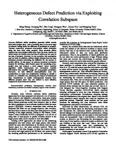
Step 5: If no more output responses can be added to the cluster, then if there are still output responses remaining that are not part of any cluster, go to step 1 to form the next cluster. Otherwise, the procedure completes. This procedure will find a good solution, but is not guaranteed to find the best solution. Other heuristic clustering algorithms can be adapted for this problem as well [Xu 05]. The amount of merging that can be performed will depend on how correlated the location of the X’s are across the output responses. An example of the distribution of X’s for one industrial circuit is shown in Fig. 4. The scan cells are plotted along the x-axis sorted in descending order from the ones capturing the most X’s down to the ones capturing the least X’s. The y-axis shows how many X’s are captured in that scan cell during the application of 3000 test vectors. This circuit has 97,643 scan cells, and out of those, only17,073 capture X’s. 90% of all the X’s are captured in 4.8% of the scan cells. This high degree of X locality can be efficiently exploited by the proposed method. Obviously the degree of correlation of the X’s is very design dependent, but the structural dependence of X generation in circuits generally leads to a highly skewed distribution. Note also that the advanced ATPG methodology described in [Czysz 10] can be adapted for the proposed method as well to enhance the amount of inter-correlation while avoiding conflicts with D’s.
Phase Shifter
M I S R
Figure 6. Partitioning Scan Slices (One MISR Signature Generated for each Partition)
Merging of the output responses is done individually for each p-th partition. For example, the output responses in the first partition of all scan vectors are merged first to minimize the number of merged responses for partition 0. Then the output responses in the second partition are merged independently from all other partitions to minimize the number of merged responses for partition 1. This is repeated for all the partitions. The control bits for processing each merged partition are loaded from the tester into an on-chip
185
RAM at the start of the test session. During the test session, the tester only needs to supply the index of the set of control bits that should be used for each MISR signature. This is illustrated in Fig. 7. For example, if for some scan vector, the response in the first partition was merged into the 3rd group, then the tester supplies the index value of 3, and onchip hardware converts that to a pointer into the on-chip RAM and fetches the appropriate control bits from the RAM to use for X-canceling of the first MISR signature. If the second partition was merged into the 2nd group, then the tester supplies the index value of 2, and so forth. So the data stored on the tester includes one copy of the control bits for each merged partial output response which are used to initialize the RAM, and then it stores one index value for each MISR signature which indicates where to fetch the control bits out of the RAM.
which stores only one set of control bits for each partition. The test vectors are then ordered so that subsequent test vectors use the same control bits for most partitions. Thus, the tester needs to only incrementally update the control bits stored in the on-chip RAM. For example, if test vector i used the same control bits as test vector i+1 for all control bits except for the p-th partition, then the tester would only need to store and reload the control bits for the p-th partition when applying test vector i+1. The size of the RAM would be limited to the number of control bits required to process p MISR signatures for scan responses using p-partitions. The data stored on the tester would be limited to an index which points to the partition to be updated along with the control bits to store in that partition. The on-chip hardware would decode the index and then store the control bits in that location for the RAM. When tester has finished updating the necessary partitions, one bit is sent to indicate that the scan response for an entire test vector is ready to be compacted using the control bits stored in the on-chip RAM.
RAM Partition 0 – Control Bits 0 Partition 0 – Control Bits 1 ...
Address
6. Experimental Results
Partition 0 – Control Bits n …
Experiments were performed on four industrial circuits. Table 1 shows the results for generating a single MISR signature for the output response of each test vector. The Xdensity is shown for each circuit which is the number of X’s divided by the total number of bits in the output response. The third column shows the size of the MISR. It must be large enough to store the maximum number of X’s in any output response. The fourth column shows the number of bits that need to be stored on the tester using conventional X-canceling as described in [Touba 07]. Comparisons of Xcanceling with X-compact and other methods can be found in [Touba 07]. The results shown here are for using 7 Xcanceled combinations which provides 99.2% error coverage, i.e., 99.2% of all non-X values are observed. The next columns show results for the superset X-canceling method proposed here also using 7 X-canceled combinations to provide the same 99.2% error coverage. The results for superset X-canceling depend on how many D’s are in the output response data. The actual locations of the D’s for these test sets were not available, so the experiments were done by randomly injecting different percentages of D’s, namely, 1% and 0.1%. In each case, the number of bits that need to be stored on the tester are shown along with the improvement factor compared with X-canceling in [Touba 07]. An improvement factor of 2 means that the compression ratio is twice as much as in [Touba 07]. As can be seen from the results, the proposed method is able to significantly reduce the number of control bits in most cases. The fewer the D’s there are, the better the results are since there are less sources of conflict when merging output responses together. Note that for Ckt-D, a very large MISR was required, and there were some cases where the proposed method did not improve results. However, the results were much better when multiple signatures per test vector were used as shown in Table 2.
Partition k – Control Bits 0 Partition k – Control Bits 1 ... Partition k – Control Bits n
Partition Counter
Index
From Tester
Figure 7. Partitioning Scan Slices (One MISR Signature Generated for each Partition)
Note that if there is a lot of variance in the number of X’s in the scan responses, then the scan responses can also first be divided into groups where within each group, the same scan slice partitioning is used. For example, some group of scan responses might have 4 partitions (i.e., compact into 4 MISR signatures) while another group might have 6 partitions. Each group would then be treated as if it were independent, and the RAM would be reloaded before each group of test vectors is applied. This encoding scheme described in this section is very efficient, but it requires the presence of a sizeable on-chip RAM. For processors and other chips that have a cache or other large RAM present for functional purposes, it can be utilized to implement this scheme. If not, then the scheme described in the next section can be used which requires only a small scratch pad RAM be present on-chip.
5. Superset X-Canceling using Incremental Update This section describes a way to perform superset Xcanceling for partial output responses without the need of a large on-chip RAM. The idea is to have a small RAM
186
Table 1. Results for Proposed Superset X-canceling using one signature for the output response of each scan vector X-Canceling Circuit
X MISR Density Size Ckt-A 2.47% 1300 Ckt-B 0.50% 1300 Ckt-C 2.75% 3000 Ckt-D 2.38% 6000
[Touba 07] Bits 3.1M 5.2M 20.9M 48.9M
7. Conclusions The proposed method provides an efficient way for exploiting correlations in the location of X’s. Three different implementations were described which can be employed based on the particular design situation. With continued increase in design size and complexity, the proposed method provides an avenue for scaling up compression to keep with expected increases in design size and complexity.
Proposed Superset X-Canceling 1% D’s 0.1% D’s Bits Impv Bits Impv 1.7M 1.8 0.47M 6.6 3.3M 1.6 0.55M 9.5 11.5M 1.8 2.5M 8.4 62.9M 0.8 21.4M 2.3
Table 2. Results for Proposed Superset X-canceling using small MISR with multiple signatures per scan response Circuit
X-Canceling MISR [Touba 07] Size
Bits
128
3.2M
256
3.2M
512
3.1M
128
5.4M
256
5.3M
512
5.2M
128
22.1M
256
21.4M
512
21.1M
128
51.6M
256
50.2M
512
49.5M
Ckt-A X-density = 2.47%
Ckt-B X-density = 0.5%
Ckt-C X-density = 2.75%
Ckt-D X-density = 2.38%
Acknowledgements The authors would like to thank L.-T. Wang, SynTest, Brion Keller, Cadence, and Ozgur Sinanoglu, NYU-Abu Dhabi for providing the output response data used in the experiments. This research was supported in part by the National Science Foundation under Grant No. CCF0916837.
Proposed Superset X-Canceling 1% D’s 0.1% D’s Partition Bits Impv Bits Impv Gran. Coarse 1.5M 2.1 1.5M 2.1 Fine 1.5M 2.1 1.4M 2.3 Coarse 2.0M 1.6 1.6M 2.0 Fine 2.0M 1.6 1.7M 1.9 Coarse 1.9M 1.6 0.5M 6.2 Fine 2.1M 1.5 0.5M 6.2 Coarse 1.1M 4.9 0.48M 11.3 Fine 1.2M 4.5 0.43M 12.6 Coarse 1.5M 3.5 0.32M 16.6 Fine 1.9M 2.8 0.41M 12.9 Coarse 2.9M 1.8 0.60M 8.7 Fine 3.1M 1.7 0.57M 9.1 Coarse 2.4M 9.2 1.1M 20.1 Fine 3.3M 6.7 1.3M 17.0 Coarse 3.2M 6.7 1.1M 19.5 Fine 4.0M 5.4 1.3M 16.5 Coarse 5.3M 4.0 1.3M 15.1 Fine 5.9M 3.6 1.4M 1.9 Coarse 21.8M 2.4 15.1M 3.4 Fine 18.8M 2.7 9.7M 5.3 Coarse 20.7M 2.4 10.4M 4.8 Fine 22.7M 2.2 8.5M 5.9 Coarse 31.8M 1.6 9.0M 5.5 Fine 27.0M 1.8 8.5M 5.8
References [Cullen 97] Cullen, C.G., Linear Algebra with Applications, AddisonWesley, ISBN 0-673-99386-8, 1997. [Czysz 10] Czysz, D., G. Mrugalski, N. Mukherjee, J. Rajski, and J. Tyszer, “On Compaction Utilizing Inter and Intra-Correlations of Unknown States,” IEEE Trans. on Computer-Aided Design, Vol. 29, Issue 1, pp. 117-126, Jan. 2010. [Gizdarski 10] Gizdarski, E., “Constructing Augmented Time Compactors,” Proc. of European Test Symp., pp. 151-156, 2010. [Hamzaoglu 99] Hamzaoglu, I., and J.H. Patel, “Reducing Test Application Time for Full Scan Embedded Cores,” Proc. 29th Annual Int. Symp. Fault Tolerant Comp., pp. 260-267, 1999. [Leininger 07] Leininger, A., M. Fischer, M. Braun, M. Richter, and M. Goessel, “Using Timing Flexibility of Automatic Test Equipment to Complement X-Tolerant Test Compression Techniques,” Proc. of International Test Conference, Paper 6.3, 2007. [Mitra 04a] Mitra, S., and K.S. Kim, “X-Compact: An Efficient Response Compaction Scheme,” IEEE Trans. on Computer-Aided Design, Vol. 23, No. 3, pp. 421-432, Mar. 2004. [Mitra 04b] Mitra, S., S.S. Lumetta, and M. Mitzenmacher, “X-Tolerant Signature Analysis,” Proc. of Int. Test Conf., pp. 432-441, 2004. [Rajski 05] Rajiski, J., J. Tyszer, C. Wang and S.M. Reddy, “Finite Memory Test Response Compactors for Embedded Test Applications,” IEEE Trans. on Computer-Aided Design, Vol. 24, No. 4, pp. 622-634, Apr. 2005. [Rajski 06] Rajski, W., and J. Rajski, “Modular Compactor of Test Responses,” Proc. of VLSI Test Symposium, pp. 242-251, 2006. [Patel 03] Patel, J.H., S.S. Lumetta, and S.M. Reddy, “Application of Saluja-Karpovsky Compactors to Output Responses with Many Unknowns,” Proc. of VLSI Test Symposium, pp. 107-112, 2003. [Sharma 05] Sharma M. and W.-T. Cheng, “X-Filter: Filtering Unknowns from Compacted Test Responses,” Proc. of International Test Conference, Paper 42.1, 2005. [Touba 07] Touba, N.A., “X-Canceling MISR – An X-Tolerant Methodology for Compacting Output Responses with Unknowns Using a MISR,” Proc. of Int. Test Conference, paper 6.2, 2007 [Wang 06] L.T. Wang, C.-W. Wu, X. Wen, VLSI Test Principles and Architectures, Morgan Kaufmann, 2006. [Wohl 10] Wohl, P., J.A. Waicukauski, and F. Neuveux, and E. Gizdarski, “Fully X-Tolerant, Very High Scan Compression,” Proc. of Design Automation Conference, pp. 362-367, 2010. [Xu 05] Xu, R., and D. Wunsch, “Survey of Clustering Algorithms,” IEEE Trans. on Neural Net., Vol. 16, No. 3, pp. 645-678, May 2005.
In Table 2, results are shown for three different sizes of MISRs, namely 128, 256, and 512. In this case, the output response for each test vector was partitioned and one signature was generated for each partition. Results are shown for different numbers of partitions (one coarse and one fine granularity). While the MISR size would need to be selected at design time, the number of partitions could be selected after the output response is already known allowing the opportunity to optimize it. The results in Table 2 show very significant improvements in the amount of compression can be obtained (up to an order of magnitude improvement for some circuits). Note that all of these results could be further improved if this methodology was incorporated into the ATPG procedure along the lines of what was described in [Czysz 10] to minimize conflicts from D’s and enable larger merged output responses. In addition, if the D’s show intercorrelation, the results could be further improved.
187