Exploring the limitations and expectations of sound source localization and visualization techniques. Dipl. Wi. Ing. Gunnar HEILMANN1; Dirk DOEBLER2; Magdalena BOECK3 1,3
gfai tech GmbH, Volmerstraße 3, Berlin-Adlershof 12489, Germany 2
GFaI e.V., Volmerstraße 3, Berlin-Adlershof 12489, Germany
ABSTRACT In the late 80’s and early 90’s institutions like NASA (USA), DLR (Germany), NLR (Netherlands) as well as companies like Boeing (USA) and Airbus (Europe) were leading the academic and technical development of sound source localizations techniques. As companies in today’s globalized world operate under pressure of competition and governmental legislation, the visualization of sound sources was and is essential for understanding a product’s acoustic behavior and therefore an integral part of product development. To make the world a quieter place, all try to improve it by understanding, reducing and controlling noise. Even 15 years after the initial market introduction of commercial Beamforming systems not everyone trusts and understands their capabilities and limitations. The aim of this paper is to present a variety of applications and results to show their possibilities and increase the understanding of the limits for different technologies for sound source localization and visualization methods. To do so, a vast selection of colorful and practical examples will provide a better understanding of what is feasible. The given examples range from small motors for digital cameras to household appliances, from cars to mining trucks, from small rooms to theatres and stadiums or from bats to elephants. Keywords: Sound visualization and manipulation.
Section V2
1. INTRODUCTION When someone is given the task of telling where a sound is coming from, several tools are at hand to fulfill said task. At first, a human’s ears can be used to gain understanding of a noise occurrence. Paired with knowledge accumulated over years, this is practice for numerous applications. Many mechanics, for example, are able to identify different noise sources inside a motor (e.g. knocking, whistling…) simply by ear. One may not need to visualize the sound at all and still be able to repair your car. Many years ago people started to extend their ears in order to achieve better localization or amplify interesting sound. The stethoscope is a very good example to amplify noise but its user has to move the receiver around and listen to each point separately and consecutively. Surprisingly, this is still a satisfactory tool for many engineers.
1 2 3
www.gfaitech.de www.gfai.de www.gfaitech.de
Inter-noise 2014
[email protected] [email protected] [email protected]
Page 1 of 9
Page 2 of 9
Inter-noise 2014
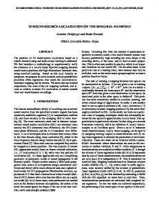
Figure 1: Acoustic array developed by Sergeant Jean Perrin (right) and used by the French Army during WWI to detect enemy aircraft.
But when it comes to research and development, one needs to meet standards and regulations as well as the expectations of management and customers. Very quickly the limits of human hearing are reached, most importantly because it only gives a subjective impression. In many cases a standard sound analysis conducted via single microphone measurements can give enough answer considering – for example – a tonal component. In such cases frequency and level can easily be obtained. It is only then that things get a bit trickier as often experts star showing numbers and graphs that usually mean nothing to non-experts. Endless discussions start over sometimes relatively simple problems. As a result, very often more microphones are introduced, resulting in even more numbers and yet more graphs. Using two microphones as intensity probes additionally supplies a vector which supplies directivity information. But of course the discussion does not end right there so more microphones are introduced. In many fields of application engineers use multichannel data recorders to acquire multiple channels of all sorts of positions and many properties like temperature, sound pressure, angle, rpm and many more. When it comes to sound, many times the sensors/ microphones are placed near very precarious points on the measurement object. It’s a common goal to get the signal closest from the point where one suspects the source of the specific signal. Many different technologies with various different names occurred over the years. Today’s engineers expect sound source localization tools to produce colorful maps with video or 3D model overlay in relation to angle or rpm, order information etc. that can be used as tools for the communication and discussion with customers, management and suppliers. Experience shows the time spent on arguments and discussion can be reduced by about 80% when results are easy to interpret and engineers start solving problems faster and together. At the first glance, Beamforming may serve that purpose. One gets beautiful color maps and they seem easy to understand. The aim of this paper is to give a better understanding of what applications can be solved as easily as one would hope for. When looking at sound source localization tools the most common commercially available products or systems are based on the well-known delay-and-sum-Beamforming method. As Dougherty says, “Classical Beamforming gives the best results for incoherent, broadband, source distributions.” The systems used in academic research may differ from industrially/ commercially used systems in array shape and microphone count, in algorithmic complexity and software features as well as in computational speed and user comfort. These industrial/ commercial Beamforming systems shall be the primary interest of this paper. Undoubtedly, both domains are completely equivalent in mathematical theory, because the real sound pressure values from the microphones and their complex Fourier transformations represent the same information content. However, from a practical viewpoint and due to different algorithmic properties, there are some quite important differences between both domains which will be explained subsequently.
Page 2 of 9
Inter-noise 2014
Inter-noise 2014
Page 3 of 9
2. Basic Principle of Beamforming 2.1 Date and general Echo Location The term “Beamforming” historically originates from active localization systems (SONAR, phased RADAR) and denotes the fact that the main lobe (the so called “beam”) of the directivity/sensitivity pattern of a discrete sensor array changes its form dependent on the actual method used to virtu ally steer the array to certain angular directions. But nowadays the term is used synonymously for active systems as well as for purely passive localization methods. When using the simplest method, classical delay-and-sum Beamforming [1], a microphone array will be successively focused at many points on a measurement plane or on an object’s surface. In theory, this focus distance can even be considered to be infinitely long which is equivalent to the model assumption of plane waves passing through the sensor array. For every individual focus point or direction, the relative runtime delays between the microphone channels are compensated for. The shifted time signals will consecutively be added up. Subsequent dividing by the channel number gives an estimated time function which is comparable in its power content to the original time signal at this focus location or, in case of an infinite focus range, from a certain angular direction. For each of those many time functions, interesting parameters such as sound pressure level can be determined easily and simultaneously. This way, a mapping of the complete sound pressure distribution in the measurement plane or on the surface of an object can be calculated . The simplest approach is the straightforward calculation of a delay-and-sum Beamforming function in the time domain. The reconstructed time function at every location x is calculated as: M
1 fˆ (x, t ) M
w f (t ). i 1
i i
(1)
i
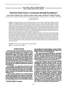
In Eq. (1), t denotes time, M is the number of microphones in the sensor array, and wi are optional spatial shading weights acting similar to the windowing coefficients applied before performing time signal spectral transforms to reduce leakage and smearing effects. But for the Acoustic Camera’s standard ring array, all wi are simply set to unity because spatial shading does not make sense in this case. Eq. (1) is also illustrated in Figure 2 below.
sound event
microphones
1
f (x, t )
i
3
ri c
4
1 fˆ (x, t ) M
w1
M
w f t i 1
i i
i
w2 w3
+
1/M
fˆ (x, t )
w4
i i min i
p(t) p(t): time function of sound pressure
f i (t )
1
fˆ (x, t )
2 3
4
t
Effective value of p at x: 1 n1 ˆ 2 pˆ eff (x) pˆ eff (x, n) f (x, tk ) n k 0
Figure 2: Principle of time domain Beamforming Inter-noise 2014
Page 3 of 9
Page 4 of 9
Inter-noise 2014
f i(t) are the recorded time functions of the individual microphones, and the Δ i are the appropriate relative time delays, which are calculated from the absolute run times τi = |ri| / c by subtracting the minimum over all τ. The symbol c denotes the speed of sound in air and |ri| = |xi - x| is the geometrical distance between the spatial position of microphone number i and the actually calculated focus point x. 2.2
Sound sources and array types
Human hearing generally works for sounds between 20Hz to 20 kHz which corresponds to three different wavelength categories. This would mean locating signals ranging from AM to FAV with the same radio receiver in terms of electromagnetic waves or using the same camera for holiday snapshots and x-ray imaging. It becomes clear that the mentioned range is extremely large when considering wavelength. (The wavelengths for 20 Hz to 20 kHz equal 17m to 1.7cm.) That means that it is very difficult to create a sensor to find sound sources for the complete range of audible wavelengths. This is one reason why microphone arrays exist in many different sizes and shapes. To measure various different sound sources, many different microphone array designs have emerged over the past years. Each application has some kind of uniqueness in time and frequency behavior. In general, one can say that smaller arrays are better suited for smaller objects as they emit short wavelengths and large microphone arrays are better suited for long wavelengths and thus large objects. Arrays can now take many different shapes. When the entire market is considered, geometries ranging from ring to wheel, spiral, snowflake, oval, spherical as well as stochastic distribution of all microphones are available these days. Some arrays are solid surface and some are acoustically transparent. Simulation tools allow engineers to try different array configurations using virtual or real sound sources in order to predict the quality of the results.
Image 3: Sphere120
Image 4: Ring32 array,
Image 5: multi shape
Image 6: Near field
array, Ø 0.60m
Ø 0.35m
array, Ø 0.80m
paddle2x24, Ø 0.35m
Sound sources come in all sizes and shapes, from small to large, stationary to transient, emitting high and/or low frequencies. The following will concentrate on practical examples of the successful application of the technology in extreme situations. 2.3
Examples of small sources and high frequency behavior.
Small objects are of course more likely to emit small wave lengths – high frequencies. Image 7 shows a small electric motor with a small gearbox. The total size is about two centimeters. The displayed frequencies are 8 – 12kHz and 12 – 20kHz.
Page 4 of 9
Inter-noise 2014
Inter-noise 2014
Page 5 of 9
Image7: Acoustic photos of a small electric motor, displayed at 5dB map dynamic, two different frequency ranges, left 8 – 12kHz and right12 – 21kHz. When looking at leakages one may find sources of less than 1mm diameter. Here an example of a sound leakage test of a box with several holes; 3mm, 2mm, 1mm and a slit of 5mm width. Inside the box is a speaker playing white noise. The acoustic photo is calculated over all frequencies and displayed at a dynamic of 30dB. On the edge of the box (where some screws where not properly tightened) additional sources appeared. The sources disappear when putting all screws in and tightening them.
Image 8: Leakage test on a box, displayed over all
Image 9: Twelve ignitions from spark plugs, sources
frequencies with a map dynamic of 30dB.
being only about 1.4mm in size, displayed over all frequencies at about 9dBA.
When the data recorder samples high enough and the microphones give a flat frequency response , mapping even beyond the hearing limits of humans becomes possible. The rule of thumb is normally to sample at about 10 times the rate of the highest frequency to be analyzed. When reaching close to that ratio one can experience time and spatial undersampling. As a result, sources may not be separated in time and space or mapped clearly. An even smaller and more high-frequent source than in Image 9 is created by bats when orienting in the air while flying. These short clicks reach very high frequencies.
Inter-noise 2014
Page 5 of 9
Page 6 of 9
Inter-noise 2014
Image 10: Jamaican Leave Nose Bat emitting between 10 to 50kHz at 4dB dynamic 2.4
Examples of large sources and low frequency behavior
The airplane industry has been performing tests of planes at 150+m distance and several hundred km/h’s velocity for many years now. Often the results are mapped on drawings A general difficulty in such applications is the distance and speed of the object in relation to the array position. On top of that, sound sources are generally broadband and overlap in the frequency doma in. This means one will need a specifically designed microphone array to provide the large dynamic range necessary to find those sources.
Image 11: Acoustic photos of airplane fly-overs Similarly difficult are pass-by measurements of high-speed trains. The most important sources at high speeds are aero dynamic sources. The issue here is the great speed (up to 400km/h) these trains reach.
Image 12: ICE Train at 250km/h calculated frequencies from 500Hz to 20kHz at 7dB dynamic Image 12 shows a train at 250km/h mapped on a stitched photo image calculated from the recorded video stream. This method provides the accurate speed profile, which a llows to compensate Page 6 of 9
Inter-noise 2014
Inter-noise 2014
Page 7 of 9
for the Doppler effect in the acoustic image even when the speed of the object changes during the passing by. In 2007 – 2010 the Michigan Stadium was undergoing some design changes. Before construction started a measurement was performed to see how the simulations of 110.00 cheering visitors match the real-life sound field. The student section was expected to be the loudest corner of the football stadium and this was confirmed during measurement and analysis. The 3D acoustic photos (Image 13) provide a quick insight on the sound field in the stadium. Surprising about the results was the fact that one can actually understand the cheer of a person in the ranks when listening to the area of interest in the acoustic image .
Some one screaming “go blue”
Image 13: Measurement at the Michigan stadium, almost 110.000 people cheering In many cases it seems impossible to locate very low frequency sources. This is correct if one needs to separate several low frequency sources. The wavelength becomes so large that an array’s angular resolution is too small. To achieve a sufficient map dynamic one would need a very large array. For most applications it is impossible to enlarge the array. In case of the stadium measurement , for example, it just seemed not practical to operate with a larger array because of logistical reasons. Another example is the interior of a car where, naturally, array size cannot exceed the size of the cabin. In some cases it is still possible to measure and map even very low frequency sources. Image 14 shows a result of a test on the actual low frequency capabilities of the Beamforming technology. To locate the sound source it is necessary to decrease the map dynamic dramatically, sometimes even to as little as 1dB dynamic. To get reliable results one needs to calibrate the microphone array very accurately. This is not sufficient to display other secondary sources with the same frequency behavior but it does provide insight on the location of the loudest sound source. Most of the time this is the starting point for further noise reduction efforts or further investigati ons with near field methods or laser vibrometry which both require more time to cover large areas.
Inter-noise 2014
Page 7 of 9
Page 8 of 9
Inter-noise 2014
Image 14: Car interior mapping of subwoofer playing a 70Hz tone inside the trunk. If the accurate dB-level are not as important as correct mapping, one can go even further to the limits of this technology. For an investigation of how elephants produce so-called “rumbles”, Beamforming was used to locate the rumbles’ origin. (nasally and/ or orally). Using an array with a diameter of 3.4m it was expected to work properly down to about 100Hz, but unlikely to provide reliable results below that range. Despite the fact that the acoustic images show very little dynamic range, source mapping is repeatable and the results show both production types on various different animals.
Image 15: Elephant’s nasal rumble calculated from 15Hz to 107Hz.
Page 8 of 9
Inter-noise 2014
Inter-noise 2014
Page 9 of 9
3. CONCLUSIONS By the nature of the technology, Beamforming produces excellent results in the mid and high frequency range (600Hz – 15kHz) and distances from thirty centimeters to a view hundred meters. The examples shown in this paper provide reliable evidence that Beamforming can also be applied outside these limits when used with caution. Instead of assuming an application is not suitable for analysis via beamforming it is advisable to go ahead and try beamforming - the results might very well be surprising. The technology is a great and relatively inexpensive starting point for sound source analysis on measurement objects that can (and very often should) be complemented by using related technologies like Near Field Acoustic Holography and laser scanning vibrometry. Considering all known limits of Beamforming it becomes clear that the boundaries are melting when experience is increasing.
REFERENCES 1. Don H. Jonson, Dan E. Dudgeon, Array Signal Processing. PTR Prentice-Hall, New York 1993. 2. What is Beamforming? R. P. Dougherty, Proceedings of the BeBeC 2010, Berlin, Germany, 2008 3. Effects of Steering Delay Quantization in Beamforming James Fung, Applied Research Laboratories, The University of Texas at Austin Literature Survey, EE 381K Multi-Dimensional Signal Processing 4. Strength and weaknesses of the calculating Beamforming in the time domain. O. Jaeckel, Proceedings of the BeBeC 2010, Berlin, Germany, 2006. 5. Efficient methods for the analysis of moving sound sources with microphone arrays A. Meyer, D. Döbler, M. Gräser, Proceedings of the BeBeC 2010, Berlin, Germany, 2014. 6. Crowd noise measurement and simulation in large stadium using Beamforming. M. Navvab, G. Heilmann, D. Sulisz, Proceedings of the BeBeC 2010, Berlin, Germany, 2008 7. Visualizing Sound Emission of Elephant Vocalizations: Evidence for Two Rumble Production Types, A. S. Stoeger, G. Heilmann, M. Zeppelzauer, A. Ganswindt, S. Hensman, B. D. Charlton DOI: 10.1371/journal.pone.0048907
Inter-noise 2014
Page 9 of 9