failure to a minimum, the development process for such applications should evolve in ... sound Web Application development process should be addressed.
Lecture Notes in Computer Science
1
Extending UML for the migration of Legacy Systems to the Web Cristina Cachero, Jaime Gómez and Antonio Párraga Departament of Languages and Information Systems University of Alicante. SPAIN Email: {ccachero, jgomez, aparraga}@dlsi.ua.es
Abstract. Migration of Legacy Systems to the Web is one of the main concerns of enterprises looking for more flexible distributed application environments. This migration process comprises the construction of a Web Interface that needs to interact in an arbitrary complex manner with pre-existent business logic modules, which must pay off prior investments. These Web Engineering concerns have been already addressed with UML, although existing proposals tend to focus on the solution space. In this article we argue that new abstractions are needed for UML to capture navigation, presentation and interaction features, particular to the Web Interface idiosyncrasy, from a conceptual point of view. Our proposal, known as OO-H Method, provides a UML extension that, departing from a UML class diagram, defines a new set of views to capture the user interface requirements. The introduction of such diagrams in a CASE tool allows the generation of fully-functional prototypes. Along the article we pay special attention to the way OO-H Method models the interaction and coupling of the Web Interface with the pre-existent business modules, including service request and parameter feeding/recovery.
1 Introduction In the last few years we have witnessed how existing and to come Web technologies have induced much more flexible distributed environments where new business opportunities have appeared, but also new risks related to software development [12]. Although the scientific community agree in that, in order to keep the possibility of failure to a minimum, the development process for such applications should evolve in a Web Engineering manner, there is no agreement at how the core activities behind a sound Web Application development process should be addressed. We have detected three main research trends, namely: (1) Regarding Web Applications as information delivery systems, where only trivial functionality is offered [11][14][3] (2) Treating Web Applications as traditional distributed applications on which standard models and methods are applied [17]. (3) Considering the Web as a Dynamic Business Web [7] where the application development consists on a process of communication and integration of Web
Lecture Notes in Computer Science
2
Services disseminated over the net and offered via often collaborating technologies such as [UDDI, DSML, SOAP,WSDL]. We believe neither of these trends properly addresses (when used in isolation) all the nuances Web Applications involve. On one hand Hypermedia modelling methods (1) attend specification, design and implementation of application interfaces but don’t tackle the necessary abstractions for specifying the interaction between interface objects and other application modules. On the other hand, most conventional modelling methods (2) center on the specification, modelling and implementation of organizational information systems and consequently lack abstractions for specifying hypermedia applications based on the hypertext metaphor, that is, Web navigation and interaction issues. Last, Dynamic Business Web (3) directs its efforts towards implementation issues such as protocols, products and tools for the integration of services, lacking a mechanism to reflect on the usability and presentation aspects of such integration. In this sense, we agree with [10] in that modelling the integration and interference of design of business logic and Web Interface design is the key factor for getting successful Web Applications. Some proposals [16] exist for the definition of interface and integration with logic that are device and technology independent. Also, business logic concerns have already been partially addressed in a number of Advanced Software Production Environments [2] that use Model Based Code Generation techniques, many of them based on UML-compliant [17] models. Our approach, known as OO-H (Object-Oriented Hypermedia) Method [9], aims at extending such UML-Compliant environments with two new features: navigation in heterogeneous information spaces and connexion with pre-existent logic modules. We aim at capturing those features by means of both UML and OCL extensions that can be integrated with pre-existing UML models. There are other proposals that apply the standard models UML provides to address Web Interface issues, and they have given as a result very complete and intuitive extensions for Web design models. That is the case of Web Application Extensions (WAE) proposed in [4], that are used in conjunction with the standard diagrams that describe the rest of the system. They are perfectly suited to reflect the design artefacts (server pages, client pages, forms, frames…) of a Web Interface, as well as to drive the implementation of such interface. However, we have detected a lack of a “general analysis navigation model” technology and device independent, not centred on the solution space level, on which to reflect on mechanisms to improve the front-end user experience. OO-H Method aims at providing one such bridging model, situated in the problem space: the navigation model and its corresponding Navigation Abstract Diagram (NAD). The NAD constitutes a complementary view to those captured in traditional UML conceptual modelling approaches, and extends a class diagram with hypermedia navigation features, providing personalized views of the system to the different user types. OO-H Method integrates this view in a design process where not only the NAD
Lecture Notes in Computer Science
3
but also an Abstract Presentation Diagram (APD), a Composition Layout Diagram (CLD) and an Interface Pattern Catalog are applied. As a result, a device-independent front-end specification is obtained. OO-HMethod completes its proposal with a CASE tool that allows a model-based code generation of a Web Interface that integrates with pre-existent logic modules. This CASE tool is actually being applied to restricted organizational information systems such as e-commerce applications. The NAD can also be used in an independent manner, and act as an intermediate diagram between the class diagram and a design proposal such as WAE. The remaining of the article is structured as follows: section 2 provides a brief overview of the OO-HMethod architecture in the context of traditional software development and its role regarding Legacy Systems. Section 3 presents our UML extension proposal and describes, by means of a comprehensive example, the use of OCL, the definition of the Navigation Access Logic and the integration mechanisms provided to connect with underlying Legacy Systems modules. Section 4 illustrates the generation process, while a brief discussion of our approach and further work is sketched in section 5.
2 The OO-H Method Architecture
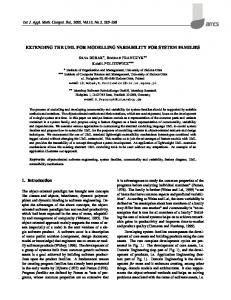
Fig. 1. Migrating a legacy system to the Web with OO-H Method OO-H Method is a generic model that provides the designer with the semantics and notation for the development of Web-based interfaces and its connection with preexistent Legacy Systems. Before applying the OO-H Method (see Fig. 1) a process of Reverse Engineering must be performed in order to get both the static and dynamic views of the system in the form of class and behaviour diagrams. This task has been already addressed in the context of UML and some supporting CASE tools [13]. One of the main contributions of OO-HMethod is that, departing from the conceptual schema obtained in a reengineering process, it extends such schema with two new
Lecture Notes in Computer Science
4
complementary views by means of three diagrams: (1) The Navigation Access Diagram (NAD), that defines the navigation and interaction view, and (2) the Abstract Presentation Diagram (APD) and the (3) Composition Layout Diagram (CLD) that together gather the concepts related interface architecture and presentation. OOHMethod provides a model compiler that generates several components. On one hand it generates the internet application front-end for the desired client platform and/or language (HTML, XML, WML). On the other hand, it also generates a “Mediator”, whose aim is wrapping both the way legacy services are going to be invoked (SOAP) and the way the interface is going to get the objects it needs to visualize while the user is navigating. Note how these “navigation data services” implement the idea of filters that is further discussed in section 3. The result is a true three-tiered internet solution. Next, we are going to introduce the core of our approach to address the migration of Legacy Systems to the Web, including each of the concepts involved in the navigation and interaction view.
3 Extending UML Semantics for the migration of LS to the Web The OO-H Method extension to the UML defines a set of stereotypes, tagged values and constraints that enables the capture of Web navigation and service interaction. Following the trend presented in [6], we have maintained the graphical symbols provided by UML when the semantics could not introduce confusion, in the philosophy that modelling constructs should not get in the way of the modelling process. In Appendix A we can see such symbols and the corresponding sterotypes. For reasons of space, in this paper only an informal presentation of the extension is given. Interested readers are referred to [8] for a deeper discussion on semantics an tagged values.
Fig. 2. Analysis Class Diagram for a Hotel Management System
In order to introduce the main concepts a small example is going to be employed thorough the paper: a Hotel Management System. An excerpt of the class diagram corresponding to the system can be observed in Fig. 2. where the “booking” associa-
Lecture Notes in Computer Science
5
tion is depicted. The booking class contains information about the hotel occupation. For each booking, the system keeps information about the client, the room and the associated arrival and departure dates. Starting from this conceptual schema, we can work on the navigation view introduced by OO-H Method for the modelling of the Interface Subsystem. Following the pattern “Use cases: work as packages” [6], the set of user navigational and functional requirements (that may have been previously encapsulated in use cases, out of the scope of OO-H Method) are the basis from where to start to construct the different Navigational Targets (NT) that make up the Navigational Access Diagram (NAD). Different requirements can be encapsulated inside the boundaries of a given NT, in order to facilitate reuse. As we can observe in Fig. 3, the NT is an organizational package that provides a view for the model management. It not only shares the package icon, but also most of the package semantics: a NT defines a namespace and it may be nested. Also, it has a given visibility and a possibly a set of access dependencies defined on it. NT contribute to an incremental development process, in which more NT can be added as new user requirements are detected and/or we advance in the interface modelling process. The NT concept provides operational scenarios [1] to describe how the proposed interface will operate. Inside a software production environment these scenarios can be prototyped long before being completely modelled and thus facilitate validation against customers at an early stage.
Lr: "Entry point"
Hotel System
Employees DN5 Management
Installation DN4 Management
DN1 Bookings
Fig. 3. NAD Level 0
For reasons of brevity we will suppose we have identified three main areas of concern for a given user-type (see Fig. 3): the management of the different hotel installations, the management of employees and, finally, the management of client bookings. The entry point to the application, represented by the “Entry Point” Requirement Link, points at a collection of links that will be accessible from the application home page. Each link drives the user to a different application area. When we enter the “Bookings” NT, we observe the diagram presented in Fig. 4. The Requirement Link “View Bookings” points at the “Booking Info” navigation class (derived from the Booking domain class), from where the user will start to navigate inside the NT. This “Booking Info” view informs the user about arrival dates, departure dates and the price each user
Lecture Notes in Computer Science
6
will pay for the room (which may differ from client to client depending on internal business rules). Also, we observe how the “Booking Info” navigation class is the source of two Internal Links (Li). OO-H Method defines a tagged value “showin” associated with links, which in the example has been set to “org” (origin) and indicates that the booking view should include (in the same Web page) not only the booking data but also information about the client (name, email, company) and the room (room number, people) that hotel booking involves. Also, in the NAD of Fig. 4 we can observe a “do New Booking” Service Link associated with the “newBooking” service. This link allows the user to invoke the service when s/he is in the context of the booking view. The semantics of this link and the associated “Booking OK” Response Link will be explained in detail in section 3.1. The “newBooking” service needs two parameters: “Client” and “Room”. The navigation paths for the user to introduce those parameters are defined inside the NT “Client Search” and “Room Search”, and two dependency arrows show the relationship the class that owns the service has with the packages where the different parameter feeding navigation possibilities are modelled.
Client Info: Client name(V) email(V) company(V)
Lr:"View Bookings" [arrivalDate>'08/01/2001']
Booking Info: Booking
Li
sendMail
arrivalDate(V) departureDate(V) customizedPrice(V)
res:"Booking OK" newBooking S Ls: "doNewBooking"
Li
Room Info: Room roomNumber(V) people(V)
DN2 RoomSearch
DN3 ClientSearch
Fig. 4. NAD Diagram for the Bookings NT
Inside OO-H Method, OCL [17] is a milestone for the generation of non-trivial interface applications. It not only allows the specification of preconditions, postconditions and invariants, but also of navigation restrictions, that is, constraints on navigation paths. In Fig. 4 we can observe how this is achieved: associated with the “View Bookings” link we can observe an OCL sample expression between brackets. This expression is called a filter. Filters can be introduced by the designer to express navigation constraints. Back to our example, the filter [arrivaldate>`08/01/2001`] restricts the object population of the target view. Also, filters can be derived from the underlying structural relationships, in which case they are called structural filters. These
Lecture Notes in Computer Science
7
filters are automatically generated and offered inside the OO-H Method environment, but they must be explicitly activated by the designer in order to be applied to the model. The reason is that, in Web environments, non contextual and/or redundant navigation paths are not only possible but common, and constitute one of the main characteristics of the hypertext metaphor. In the following section we are going to briefly revise the main OCL concepts and extensions OO-H Method includes to allow the connection to services.
3.1. Connection to Services The modeling of connection with pre-existent logic modules implies the management of the user interaction, understood as not only user navigation but also user input, for which OCL was not initially suited [17]. Consequently, and additionally to the standard uses of OCL, OO-Hmethod provides an OCL extension that gives support to the following requirements: 1. Specifying visibility restrictions for classes, attributes, relationships and noncontextual navigation (filters). 2. Getting (sets of) user-input values provided by the user at execution time. 3. Getting method parameters from context and/or providing possible navigation paths for its selection. This feature will be further discussed below. In order to support (2), our extension includes the definition of two new tokens that have been added to the OCL grammar, namely $ (for single value input) and $$ (for value collections input). They represent user values that must be introduced by the user at execution time. Also, for string comparison of values, OO-H Method allows the use of the traditional wild characters * and ? Together with OCL, OO-H Method introduces a new construct, the “Service Link” (see Fig. 4), to support at NAD level the user interaction modelling. As commented above, the departing point from where OO-H Method models this interaction is a UML class diagram. In this diagram every accessible service must be encapsulated either in a domain or utility class (possibly after a reengineering process). Many general tagged values for the services are provided by the Class Diagram definition of that service. These include both general information (whether it is a class or an instance service, value of the isQuery attribute, returning data type, etc) and information about its parameters (parameter data type, whether it is an “in”, “out” or “in/out” parameter, its mandatory or optional character, a default value, etc.). However, the user-service interaction characteristics are, as the rest of the navigational model, defined at NAD level. In order to model such interaction, OO-HMethod distinguishes between five types of parameters, which can be seen in Table 2. Hidden parameters are not showed in the interface, and so acquire the default value if provided. NAD default values overwrite Class Diagram default values. Constant parameters appear on the interface, but are not editable. User-Dependent parameters can be
Lecture Notes in Computer Science
8
further divided into User Input parameters and User Navigation Parameters. Inside User Input parameters, we distinguish between Immediate input (the user enters values by means of a textbox e.g.) and Selection input (the user introduces values choosing them from a list). On the other hand, User Navigation Parameters may imply getting the values from previously navigated routes (Contextual) or navigating again through the links and classes (Non Contextual), and thus refreshing Context information. CLASSIFICATION OF SERVICE PARAMETERS IN NAD Hidden Constant User-Dependent User Input User Navigation Inmediate Selection Contextual Non contextual Table 1. NAD Parameter Types
When the introduction of parameters implies the user navigation, this navigation may be specified in two ways: 1. Definition of the source and target link for the navigation. Whole paths to the links are needed when they are not included in the same package than the service. That implies reuse of the information and navigation structures defined in the NAD. 2. Introduction, by means of OCL expressions, of the whole navigation path. That mechanism is useful when the NAD has many navigation deviations, and we are interested in the user to follow just one (or a small set) of them. Also, in order to specify the visualization of return values and/or the values of the “out” or “in-out” parameters once the service has completed, OO-H Method uses the same navigation specification mechanism. Back to our example, the “newBooking” service has defined the parameters “Client” and “Room” as navigation parameters. As we can observe in Fig. 5, the NT corresponding to parameter input offers a set of alternatives, namely “Search by Type”, “Search by Room Number” or “Search among all rooms”. If we set the “Find Room” as the source link for the parameter input, and “Room Selected” as the target link, all possible paths in between will be available for the user to enter the parameter once s/he has activated the service. If, on the contrary, the designer introduces a given path such as “findRoom->allRooms” the user will be only offered the possibility to choose among a list of rooms, while the rest of alternatives remain hidden. All these paths can be seen in Fig. 5.
Lecture Notes in Computer Science
9
Lr:"findRoom"
Li:"byType"
find a room
Li:"byRoomNumber"
Search by type: RoomTypes description(V)
Li:"allRoomsOfType"
Li:"allRooms"
Room Search: Room roomNumber(V) floor(V) people(V)
ExP:"roomSelected"
Fig. 5. The “Room Search” NT
Once all the user-input has been gathered by the interface module, it must be passed to the Legacy System in order for it to invoke the service and return the results. This task is performed by the “Mediator”, which in the actual state of implementation of the CASE tool uses SOAP[15] for this invocation, although it might use any other technology for connecting distributed systems available in the market. Due to lack of space, this aspect of the environment remains out of the scope of this article. We have already mentioned that the OO-H Method also includes a design model (APD and CLD diagrams) that captures interface architecture and presentation. Different perspectives of the interface are captured in different XML templates[9]. The result is a graph of interrelated XML pages whose structure is showed in the APD and that can be further manipulated in the CLD diagram, both to animate the model before generation and to improve its visual appearance. Although outside the scope of this article, a brief snapshot of those diagrams is provided as part of the generation process presented in the following section.
4 Generated Prototype Our approach is currently supported by a CASE tool that provides an operational environment to support the methodological aspects of OO-H Method. It simplifies the design and implementation of web-based Information Systems from an object-
Lecture Notes in Computer Science
10
oriented perspective, providing a comfortable and friendly interface for elaborating the OO-H Method models. The most interesting contribution of this CASE environment is its ability to generate the Web Application front-end in well-known industrial software development environments. Fig. 6 shows a snapshot of the CASE tool. It captures the different diagrams that complement those that UML provides, namely: the Class Diagram, a NAD instance for the ‘Bookings’ NT, the APD generated departing from the NAD specification and, finally, the CLD that provides the designer a easy an intuitive framework for prototyping the Web Interface and checking the connection with pre-existent business logic.
Fig. 6. The OO-H Method CASE Tool
The interface generated from the XML specification corresponding to the Hotel Management system is shown in Fig. 7 and 8 .
Fig. 7. View Bookings
Fig. 8. Input Parameters
The process is as follows: first, the model compiler tool looks for the page template derived from the Application Entry Point (see Fig. 3). When the user clicks on the
Lecture Notes in Computer Science
11
entry point to the “Booking” NT (see Fig. 4), included in the “Hotel System” collection (see Fig. 3), the view corresponding to the “Bookings” that will take place after July 2001 are shown (see Fig. 7). Also in Fig. 7 we observe the link that causes the ‘newBooking’ service to be launched. Clicking on such links drive us to the screen showed in Fig. 8, where we can choose among different ways to select both the room and the client involved in the booking process. This sample application has been animated using the CLD navigation feature. The generation process keeps faithful to what is showed in the CLD, and in this example has been performed using ASP’s and DCom components as the chosen server technology, and HTML as the chosen client technology.
5 Discussion and Futher Work Web Applications development methods are facing the problems traditionally associated with definition of a robust and sound software production method: how to go properly from specification to implementation. UML provides a modelling language that can be successfully extended for addressing these new conceptual features, mainly related to navigation, interaction and presentation, that are basic in Web environments. While design activities, tightly related to application architectures and technology facilities, have been already addressed inside the UML community in a rigorous way [4], we believe a previous navigation conceptual design that takes into account user information and functional requirements is also needed. One of the main reasons is that Web technology is in continuous evolution, and so providing deviceindependent capabilities will be a constant requirement, supporting the idea of implementing the same conceptual schema in different target devices, depending on the customer choice. This paper offers a simple, yet very powerful way of modelling the interaction features needed to provide parameter values, invoke Legacy System services and customize the visualization of results. Unlike in traditional applications, Web Applications tend to show information in different related information views, each one focusing on a single cognitive aspect. This navigation through parameter values and responses has not been, as far as we know, addressed in any approach aiming at modelling such systems, and user interaction features have been constrained to simple User Input (either directly typed or using list selection mechanisms). Also, the use of OCL and the UML-compatible basis of the Navigation Access Diagram facilitates the comprehension and usability of the model. OO-H Method is still improving its integration capabilities (encapsulated in the Mediator, see Fig. 1) when dealing with Web Services distributed over the net. Also, in its current stage of development, aspects such as service composition, asynchronous execution of services, security concerns or very sophisticated front-ends have not been
Lecture Notes in Computer Science
12
taken into account. We are conscious that using a UML dialect (with a new type of diagram) is a drawback for its integration in existing tools, and so we are also working on the definition of NAD-equivalent diagrams that make use of standard UML diagrams. On the other hand, the CASE tool is still being tested, and new capabilities will be added as we increase the number and type of modelled applications.
6 References 1. 2. 3. 4. 5. 6. 7. 8.
9. 10. 11. 12. 13. 14. 15. 16. 17. 18. 19. 20.
J. Bergey, L. Northrop and D. Smith. Enterprise Framework for the Disciplined Evolution of Legacy Systems. Technical Report CMU/SEI-97-TR-007. Oct. 1997 R. Bell. Code Generation from Object Models. Embedded Systems Programming, vol 3 pgs. 1-9. 1998 S. Ceri, P. Fraternali, and A. Bongio. Web Modeling Language (WebML): a modeling language for designing Web sites. WWW9 Conference. 05 2000. J. Conallen. Building Web Applications with UML. Object Technology Series. Addison Wesley. Dec. 1999. Directory Services Markup Language (DSML). http://www.dsml.org/ P. Evitts. A UML Pattern Language. Software Engineering Series. MacMillan Technical Publishing. Feb. 2000. Gartner Group, Inc. The Future of Web Services: Dynamic Business Webs. Market Analysis. Feb. 2001. J. Gómez, C. Cachero, and O. Pastor. Extending a Conceptual Modelling Approach to Web Application Design. In CAiSE ’00. 12th International Conference on Advanced Information systems, volume 1789, pages 79–93. Springer-Verlag. Lecture Notes in Computer Science, 06 2000. J. Gómez, C. Cachero, and O. Pastor. Conceptual Modelling of Device-Independent Web Applications. IEEEMultimedia. Special Issue on Web Engineering, pages 26-39. IEEE, 04 2001. F. Manola. Technologies for a Web Object Model. IEEE Internet Computing, pages 38– 47, January 1999. G. Mecca, P. Merialdo, and P. Atzeni. Araneus in the era of XML. IEEE Data Engineering Bulletin, 22(3):19–26, September 1999. S. Murugesan, Y. Deshpande, S. Hansen, and A. Ginige. Web Engineering: A New Discipline for Development of Web-based Systems. In First ICSE Workshop on Web Engineering, International Conference on Software Engineering, 05 1999. Rational Home Page. http://www.rational.com D. Schwabe and R. Almeida Pontes. A Method-based Web Application Development Environment. In Position Paper, Web Engineering Workshop, WWW8, 1999. SOAP: Simple Object Access Protocol. http://www.develop.com/soap/ UIML http://www.uiml.org UML Specification. V1.3 June 1999. http://www.rational.com/uml/index.jsp UDDI: Universal Description, Discovery and Integration. http://uddi.microsoft.com Jos Warmer and Anneke Kleppe. The Object Constraint Language. Precise Modeling with UML. Object Technology Series. Addison Wesley. Oct. 1998. WSDL: Web Services Desc. Language. http://msdn.microsoft.com/xml/general/wsdl.asp
Lecture Notes in Computer Science
Appendix A Corresponding UML stereotypes for the OO-H Method extension
13