prefabricated core, systems can be build faster. Modeling and development of common parts and variants have to be supported by methods and notations.
Integrated Design and Process Technology, IDPT 2000 Printed in the United States of America, June, 2000
© 2000 Society for Design and Process Science
EXTENDING THE UML TO MODEL SYSTEM FAMILIES Matthias Riebisch, Kai Böllert, Detlef Streitferdt, and Bogdan Franczyk* Ilmenau Technical University Germany *tranSIT GmbH Ilmenau University of Essen Germany
ABSTRACT The system family paradigm aims towards developing several applications out of a domain with just one underlying architecture. The foundation of this core architecture are common properties. With this prefabricated core, systems can be build faster. Modeling and development of common parts and variants have to be supported by methods and notations. This paper extends the Unified Modeling Language (UML) to model variants during analysis and design. The built-in extension mechanisms of the UML are used without changing the metamodel. An example demonstrates the application of the extension. INTRODUCTION Developing a family of software systems instead of a sequence of separate systems offers many economic advantages. Gathering information about common properties of the systems enables the development of common, reusable core assets of the family. Information about differences between the family members can be used for the development of an extensible architecture of the common core assets. If this knowledge is applied, the “extension points” can be designed systematically. The architecture of the core assets is rarely subject to changes during further development, causing less degeneration of the architecture than in the conventional way of system development. This results in a longer usage period of the architecture, so higher investments in architecture and design will pay back eventually. Because of the higher degree of prefabrication, the development effort for a system as part of a family is lower than the effort for building a single system. As a result, the development process can be performed by a smaller team in a shorter time (Clements and Northrop, 1999).
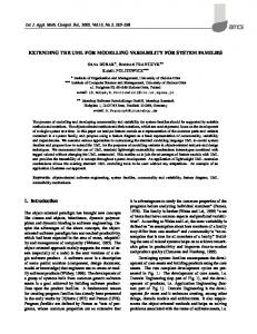
In this paper we continue from our previous work on evolving single systems towards families of systems (Riebisch and Franczyk, 1999). We present an initial step for modeling system families using the Unified Modeling Language (UML) (Rumbaugh et al., 1999). The remainder of this paper is organized as follows: First, we examine feature models as a basis for system family modeling. In the next section we propose a notion for designating the model elements in UML diagrams that are different across the members of a system family. This notion is illustrated by an example. Finally, we conclude by identifying areas of future work. FEATURE MODELS Feature models are a means to describe mandatory, optional, and alternative properties (so-called features) of concepts within a domain. An important part of every feature model is the hierarchically organized feature diagram, describing the features within a tree. The tree’s root specifies the concept being described; the nodes represent the features. A feature is mandatory unless an empty circle is attached to its node, indicating an optional feature. A set of alternative features is depicted by an arc spanning two or more edges of feature nodes (Kang et al., 1990). Fig. 1 shows an example of a feature diagram that lists possible features of an automated teller machine (ATM). Mandatory features of an ATM are, for instance, “money slot” and “debit card reader”, whereas a “receipt printer” is optional. To authenticate customers, two alternatives, “PIN check” and “biometric check”, are available.
MODELING SYSTEM FAMILIES Applied to system family modeling, feature models are used to describe the common and variable features of the members of a system family. Mandatory features whose super-features are neither optional nor included in sets of alternatives represent the common features shared by all family members. For example, the commonality of the ATM consists of the features “money slot” and “debit card reader”. These common features are implemented as reusable components and frameworks. All other features are called variable features. Family members may differ from each other with respect to these variable features, because they may or may not choose to implement a variable feature. For each family member there is a list called configuration map, which contains the choice of variable features for a member (see Tab. 1). The configuration map also references the elements of the design model that are affected by the variable features. The process for developing system families using feature models looks as follows. With given requirements and domain analysis information the modeling process is started. The feature model describes the common and variable features of the architecture which has to be designed in the next step. The system family architecture is abstract and has to be instantiated for a family member through a configuration step (Riebisch and Franczyk, 1999). The resulting family member configuration contains just the needed features for the specific problems addressed by this member. Compared to single system modeling, system family modeling requires extended diagrams. Diagram elements describing common features of the family are identical to conventional models. They are used to describe all aspects of a model, e.g. architecture, static structure, dynamic behavior, and interfaces. For these aspects the diagrams of the UML can be used without modification. The adaptation of diagram elements to express variability is essential for distinguishing between common model elements and variable model elements. Diagram elements implementing variable features need to be specifically designated to give analysts and designers information about: • •
constraints between features and their implementation configuration aspects of features.
In particular, such elements must be associated with their corresponding feature, i.e. they must name the feature to define a reference to the feature model. This association is essential to determine if diagram elements implement (part of) optional or alternative features. In the latter case the available alternatives and the corresponding diagram elements implementing these alternatives can also be determined. References between feature model,
design, and implementation should be supported by modeling tools and explored by other CASE tools. They allow automated code generation and configuration of family members. DESIGNATING VARIABLE MODEL ELEMENTS Currently, the UML does not provide a notion to designate variable model elements because the UML is targeted at modeling single systems rather than families of systems. Therefore, the UML needs to be extended what can be done either by using the UML’s own extension mechanism or by changing the metamodel underlying the UML. Although the latter option offers the highest degree of flexibility, we have not taken it into consideration because the metamodel is not accessible or difficult to change in existing UML tools. Instead, we use the lightweight extension mechanisms defined in the UML, namely stereotypes and tagged values. Stereotypes are used to mark, classify, or introduce new model elements. Every model element may be annotated with at most one stereotype, which is depicted in front of an element’s name enclosed in guillemets (or double angle brackets). The UML already predefines some stereotypes, e.g. «metaclass». Tagged values are used to specify additional characteristics or attributes of model elements. Each tagged value consists of a key—value pair, which appears after an element’s name in curly braces, e.g. {author = kb}. If more than one tagged value is associated with an element, the values are separated by commas. To designate model elements as being variable, we introduce the new stereotype «variant». Furthermore, every element that is annotated with this stereotype must have a tagged value with the key “feature”. The key’s value is a string which refers to the name of a feature in the feature model and, hence, provides the link between the feature and its representation in the design of the system. In other words: These tagged values maintain the traceability from the results of the domain analysis phase to the results of the design phase and vice versa. Fig. 2 and 3 illustrate the usage of the UML extension in activity diagrams and component diagrams, respectively. The activity diagram shows the steps to withdraw money from an ATM: insert debit card, authenticate customer, enter amount, withdraw money, and print receipt. One point at which ATMs may differ from each other is the way the authentification of customers is done (cf. Fig. 1). Therefore, the activities implementing those alternatives, “Authenticate by PIN”, “Check fingerprint”, and “Check iris”, are designated as variable model elements by annotating the stereotype «variant». Traceability from activities to features is possible through the tagged value named “feature”. For
instance, the activity “Check iris” corresponds to the feature “iris check”. The same principle applies to the component diagram in Fig. 3, e.g. the component “ReceiptPrinter” implements the optional feature “receipt printer”. Within a configuration step features have to be selected. An if-condition is implicitly given in the feature configuration. According to the chosen features the activity diagram is processed. As a result, the semantics of the if-condition element in the activity diagram is changed to process the selected variant set for each member of the system family. In general, stereotypes and tagged values could be added to all model elements, making it possible to designate every model element as being variable. Experience, however, has shown that this results in quite complex models which are – without sophisticated tool support – difficult to understand and maintain. CONCLUSION The presented approach offers a consistent way for modeling the variability of system families using the UML. The adaptations of UML diagram elements are restricted to the predefined extension mechanisms stereotype and tagged value. In our future work, these extensions will be provided for all relevant diagram elements. Variability aspects of analysis and design methods have to be investigated in more detail. As a consequence, tool support for system family development methods has to be developed.
In order to reach more comprehensive support for system family modeling the next step is the integration of feature models into the UML. This work requires wide cooperation among the object-oriented community in order to extend the UML metamodel and the OMG standards. Currently, the need for effective method and tool support is restricted by informal definition and application of diagrams. More concise formalization of semantics would allow the development of better consistency checking and automation tools. REFERENCES Clements, P., Northrop, L. M., 1999, “A Framework for Software Product Line Practice”, Software Engineering Institute, Carnegie Mellon University, Pittsburgh. Kang, K., Cohen, S., Hess, J., Novak, W., Peterson, A., 1990, “Feature-Oriented Domain Analysis (FODA) Feasibility Study”, Technical Report CMU/SEI-90-TR021, Software Engineering Institute, Carnegie Mellon University, Pittsburgh. Riebisch, M., Franczyk, B., 1999, “Evolutionary Development of Frameworks – from Projects to System Families”, Proceedings IDPT ’99, Kusadasi, Turkey, Society for Design and Process Science. Rumbaugh, J., Jacobson, I., Booch, G., 1999, “The Unified Modeling Language Reference Manual”, Addison-Wesley.
FIGURES
ATM
money slot
authentification unit
PIN check
debit card reader
biometric check
iris check
fingerprint check
Fig. 1 Feature diagram of an ATM
receipt printer
mechanical protection
wall shielding biometric sensorinstallation window
Start withdrawal
Insert debit card Open window {feature = shielding window} Authent icate by PIN {feature = PIN check}
Check fingerprint {feature = fingerprint check}
Check iris {feature = iris check}
Ent er amount
Check withdrawal Return debit card Withdraw amount Print rec eipt {feature = rec eipt printer} Close window {feature = shielding window} End withdrawal
Fig. 2 Activity diagram for withdrawing money from an ATM
MechProtecti on
ATM
WallUnit {feature = wall installation} MoneySlot ShieldingWindow {feature = shielding window} Authenti ficatio n Unit
DebitCard Reader
Keypad {feature = PIN check}
Receipt Printer {feature = rec eipt printer} FingerprintSensor {feature = fingerprint check} IrisReader {feature = iris check}
Fig. 3 Component diagram for implementing an ATM
TABLES System All All MED-99 MED-99 MED-99 SED-1034 SED-1034 SED-1034
Variation point n/a n/a Authentification unit Receipt printer Mechanical protection Authentification unit Receipt printer Mechanical protection
Feature debit card reader money slot fingerprint check receipt printer n/a PIN check n/a shielding window
Design references readAccNum(); updateBalance() withdrawAmount() identifyUser(); getBIC() printReceipt() n/a identifyUser(); getKey() n/a PaneModule; LockingModule
Tab. 1: Configuration map for two types of ATM systems