Letter www.acsami.org
Facile Method to Enhance the Adhesion of TiO2 Nanotube Arrays to Ti Substrate Dongliang Yu,†,‡ Xufei Zhu,† Zhen Xu,‡ Xiaomin Zhong,†,‡ Qunfang Gui,†,‡ Ye Song,*,† Shaoyu Zhang,† Xiaoyuan Chen,‡ and Dongdong Li*,‡ †
Key Laboratory of Soft Chemistry and Functional Materials of Education Ministry, Nanjing University of Science and Technology, Nanjing 210094, China ‡ Shanghai Advanced Research Institute, Chinese Academy of Sciences, 99 Haike Road, Zhangjiang Hi-Tech Park, Pudong, Shanghai 201210, China S Supporting Information *
ABSTRACT: The weak adhesion of anodic TiO2 nanotube arrays (TNTAs) to the underlying Ti substrate compromises many promising applications. In this work, a compact oxide layer between TNTAs and Ti substrate is introduced by employing an additional anodization in a fluoride-free electrolyte. The additional anodization results in an about 200 nm thick compact layer near the nanotube bottoms. Scratch test demonstrates that the critical load of TNTAs with the compact oxide layer is a more than threefold increase in comparison with those without the compact layer. Moreover, this facile method can also improve the photoactivity and supercapacitor performances of TNTAs markedly. KEYWORDS: TiO2 nanotube, adhesion, fluoride-rich layer, compact oxide, photoelectrochemistry, supercapacitor oxide films are formed in fluoride-free electrolytes. It has been generally accepted that fluoride ions play a key role in the formation of the self-organized oxide nanotubular structure.15 The high-field migration of small fluoride species would compete with oxygen ion migration through the amorphous nanotube bottoms during anodization.12,16 The migration of fluoride species was reported to have twice the speed of the oxygen ion movement and thus lead to their accumulation at the TiO2/Ti interface,17 resulting in a fluoride-rich TiO2 layer (FRL) which has a thickness of a few tens of nanometers and is water-soluble.15,16 The existence of FRL is believed to be the main reason for the poor interfacial adhesion.11 Thus, the elimination of the FRL may be an effective approach to enhance the adhesion strength. Here, we propose a facile method to improve the adhesion of TNTAs to the Ti substrate. That is, an additional anodization was performed in a fluoride-free electrolyte (5 wt % H3PO4 in EG) after the fabrication of TNTAs in a traditional fluoridecontaining electrolyte (0.5 wt % NH4F in EG) (for experiment details, see the Supporting Information). Thus, a compact oxide layer was introduced designedly to bury the FRL, resulting in a better adhesion quality.
A
nodic TiO2 nanotube arrays (TNTAs) have attracted growing interest because of their unique morphology and physicochemical properties. TNTAs have been intensively investigated for a variety of applications including solar energy harvesting,1−3 energy storage,4,5 photocatalysis,6 and biomaterials.7,8 However, it has been well-documented that TNTAs are prone to peeling off from the underlying Ti substrate because of the weak adhesion between them.9−12 This phenomenon was also noticed in our experiments. The poor interfacial adhesion between the TiO2 nanotube layer and the Ti substrate would significantly compromise many exciting properties and applications of TNTAs, especially when the Ti substrate was used directly as electrode (e.g., solar cells and supercapacitors). To improve the adhesion of TNTAs to the substrate, researchers have recently made great efforts. For example, Schmuki et al.13 converted TNTAs to their semi-metallic form by an acetylene treatment. They demonstrated that carbon incorporated into the microstructure of the TiO2 nanotube layers was responsible for the enhancement of their mechanical strength. Xiong et al.14 annealed TNTAs in air and found that the adhesion of TiO2 nanotube layers was improved with the annealing time. Unfortunately, these methods for the improvement of the adhesion strength are limited. It is urgent to seek a facile and effective way to enhance the adhesion of TNTAs to the Ti substrates. As is well-known, the fabrication of TNTAs is commonly carried out in fluoride-containing electrolytes, while compact © 2014 American Chemical Society
Received: March 17, 2014 Accepted: May 21, 2014 Published: May 21, 2014 8001
dx.doi.org/10.1021/am5015716 | ACS Appl. Mater. Interfaces 2014, 6, 8001−8005
ACS Applied Materials & Interfaces
Letter
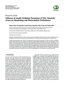
Figure 1. FESEM images of top view (left) and cross-sectional view (right) of TNTAs (a, b) without and (c, d) with an additional anodization in 5 wt % H3PO4 solution in EG.
Figure 2. Curves of acoustic output and frictional force versus load during the scratch test (lower panels), and the corresponding optical microscopy images of scratches (upper panels) on the annealed TNTAs (a) without and (b) with the additional compact oxide layer.
for that with the compact oxide layer (Figure 2b). That is, the introduction of the compact oxide layer leads to a more than threefold increase of the adhesion strength between TNTAs and the Ti substrate. The enhanced adhesion can also be observed obviously from the corresponding optical microscopy images of the scratches on TNTAs (upper panels, Figure 2a, b). In addition, from the dependences of frictional force versus load during the scratch test (Figure 2), it can be seen that the frictional forces under the same load markedly increase for the TNTA film after the additional anodization treatment in the fluoride-free electrolyte, also indicating an increased adhesion of the samples. In general, when TNTAs are fabricated in fluoride-containing organic electrolytes, it is believed that the TiO2 nanotube wall consists of two different regions: an outer shell of the tube (OST) and the inner shell of the tube (IST). In particular, there also exists an additional interface layer, i.e., FRL, between
Figure 1 shows the FESEM images of TNTAs with and without the compact oxide layer. These TNTA films have a thickness of ∼7 μm and an outer diameter of nanotubes of ∼170 nm on average. In addition, the top view shows that the additional anodization in the fluoride-free electrolyte has no effect on the surface structure of TNTAs (Figure 1a, c). The additional anodization leads to a ∼200 nm thick compact oxide layer between TNTAs and Ti substrate, as shown in Figure 1d. The hemispherical bottoms are buried in the compact oxide layer, and the TNTAs are still well-aligned and neatly. Because the flat layer of compact oxide connects with the Ti substrate directly instead of the FRL, it is expected that the adhesion between TNTAs and the Ti substrate would be enhanced. The scratch test was performed on these samples to evaluate their adhesion properties. Their Lc values can be obtained from Figure 2 (lower panels). The TNTA film without the compact layer has an Lc value of ∼4 N (Figure 2a), while the Lc is ∼13 N 8002
dx.doi.org/10.1021/am5015716 | ACS Appl. Mater. Interfaces 2014, 6, 8001−8005
ACS Applied Materials & Interfaces
Letter
Figure 3. Schematic of TNTAs on Ti substrate (a) without and (c) with the additional compact oxide layer. XPS depth profiles taken from the bottom parts of the lifted-off TiO2 nanotube layers (b) without and (d) with the compact layer.
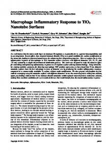
Figure 4. (a) Photocurrent response of pristine and additionally anodized TNTAs irradiated under simulated solar light for 60 s light on, (b) the LSV curves of pristine and additionally anodized TNTAs, the inset table shows the corresponding photoelectrodes’ performance. (c) Cyclic voltammograms of H-TNTAs without and with the compact layer at 100 mV s−1, (d) Galvanostatic charge−discharge curves of H-TNTAs without and with the compact layer at a charge−discharge current density of 0.1 mA cm−2. The inset shows the capacitance retention vs. cycle number up to 500 cycles.
the formation of gaps or voids between TNTAs and Ti substrate.16,18 This chemical dissolution of the FRL was suggested to be the main reason for the poor adhesion strength.11 Figure 3b and 3d present XPS depth profiles
the bottom of the nanotubes and the Ti substrate as mentioned above (schematically illustrated in Figure 3a).16 Previous studies demonstrated that the chemical dissolution of the FRL would take place due to its water solubility, which leads to 8003
dx.doi.org/10.1021/am5015716 | ACS Appl. Mater. Interfaces 2014, 6, 8001−8005
ACS Applied Materials & Interfaces
Letter
resistance between TNTAs and the Ti substrate, which is in agreement with the results assessed from electrochemical impedance spectroscopy (see Figure S3 in the Supporting Information). In the high-frequency region, the Nyquist plot for the TNTAs with a compact layer shows a smaller semicircle diameter than that for the pristine TNTAs, indicating its low charge transfer resistance (Rct). Thus, it can be deduced that the voids resulted from the FRL play a more dominant role in increasing the Rct compared with the compact layer, although the compact layer increases the thickness of the semiconductor. In addition, the introduced compact oxide layer was also found to improve the supercapacitor performances of the TNTA samples. More recently, we have reported an electrochemical hydrogenation doping method to enhance electrochemical properties of TNTA films as supercapacitor electrode materials.19 The TNTAs treated by the electrochemical hydrogenation doping are abbreviated as H-TNTAs. Images c and d in Figure 4 present typical cyclic voltammograms and galvanostatic charge−discharge curves of H-TNTAs without and with the compact layer. Evidently, H-TNTAs with the compact layer exhibit a larger integrated area for cyclic voltammograms and a longer discharge time for galvanostatic charge−discharge process compared with the ones without the compact layer. The presence of the compact layer leads to a 43.4 or 21.2% increase in capacitance calculated from the data of cyclic voltammograms or charge−discharge curves, respectively. Nevertheless, both of the H-TNTA elctrodes have similar cycling stability. As shown in the inset of Figure 4d, after 500 cycles the specific capacitance of H-TNTAs with and without the compact layer still retain 94% and 93% of the initial capacitance, respectively. Further, it is worth mentioning that the pristine TNTA films were found to be prone to detachment from the Ti substrate during the hydrogenation doping due to the impact of H2 evolution. However, the TNTA films with the compact layer can withstand a relatively long doping time. These findings confirm that our method can not only improve the adhesion strength but also enhance their electrochemical properties, such as photoelectric and supercapacitor performances. In summary, a facile method to enhance the adhesion of TNTAs to the underlying Ti substrate is presented. By employing an additional anodization of the Ti foil with the formed TNTAs in a fluoride-free electrolyte, a compact oxide layer is introduced to bury the original FRL which is believed to be responsible for the poor adhesion. The existence of ∼200 nm thick compact oxide layer leads to a more than threefold increase in the adhesion strength. And no appreciable change in the morphologies of the ordered TNTAs is observed after the additional anodization. Furthermore, TNTAs with the additional compact oxide layer demonstrate better PEC performance and increased capacitance.
through the bottom parts of the lifted-off TiO2 nanotube layers. The XPS depth profile analysis on the pristine TNTAs (Figure 3b) shows that the atomic concentration of fluorine is very high at the beginning of sputtering, which confirms the existence of the FRL at the interface of Ti substrate and TNTAs, whereas for the TNTAs with a compact layer, the depth profile analysis implies that the FRL almost disappears, as shown in Figure 3d. When the additional compact layer was formed in fluoride-free electrolyte (H3PO4), the fluorine species in the nanotube film resulting from the anodization in the fluoride-containing electrolyte might also migrate to the TiO2/Ti interface under high electric field. Therefore, there also exists a certain amount of fluorine at the bottom of the nanotube layer (Figure 3d) due to the fast migration of fluorine species. However, the compact oxide layer has effectively suppressed the accumulation of fluorine species at the TiO2/Ti interface, which is believed to be favorable to improve the adhesion. Further, from the depth profiles in Figure 3d, an obvious turning point can be observed after around 30 min sputtering, which is likely to correspond to the transition from the compact layer to the nanotube layer. Besides, we also fabricated the additional compact oxide layer in H3PO4 aqueous electrolyte. The corresponding FESEM image shows almost the same morphology with that formed in the EG-based electrolyte (see Figure S1 in the Supporting Information). Its XPS depth profile also confirms the disappearance of the FRL (see Figure S2a in the Supporting Information). It is worth mentioning that P 2p peak can be found after ∼6 min sputtering (see Figure S2a in the Supporting Information) in the compact layer formed in H3PO4 aqueous solution, in contrast, P 2p peak cannot be recognized for the compact layer formed in H3PO4 EG solution (see Figure S2b−d in the Supporting Information). The inhibition effect on the incorporation of phosphorus species into the oxide is probably related to the high viscosity of the EG solution. The presence of the above-mentioned voids is apparently unfavorable for the close contact between TNTAs and the Ti substrate. Further, the electrolyte may access to the Ti substrate through the voids among the FRL, as schematically shown in Figure 3a, which would be detrimental to the photoelectrochemical (PEC) performance. The additional anodization in the fluoride-free electrolyte delivers a compact oxide layer that enwraps FRL and acts as an intermediate layer to connect with the underlying Ti substrate tightly, as schematically shown in Figure 3b. In addition, the compact oxide layer will prevent the attack of electrolyte on the Ti substrate, and in turn could increase the shunt resistance in photovoltaic and PEC water splitting cells. As a demonstration, the PEC water splitting performances of the TNTAs were investigated under simulated solar illumination (100 mW cm−2) from a Xe lamp coupled with an air mass 1.5 global (AM 1.5G) filter (Newport no. 94063A). Figure 4a shows the photocurrent response of TNTAs with and without the compact oxide layer under simulated solar light for 60 s light on at a constant bias of 0 V. Figure 4b displays the LSV curves, where the performance parameters are also listed in the inset. Clearly, the treated TNTAs exhibit enhanced photocurrent densities, increased shunt resistance and decreased series resistance. Besides, the treatment also improves the fill factor and efficiency. The obviously increased shunt resistance can be attributed to the additional compact layer, which prevents the attack of electrolyte on the Ti substrate. The slightly decreased series resistance should benefit from the reduction of the contact
■
ASSOCIATED CONTENT
* Supporting Information S
Experimental details, electrochemical impedance spectroscopy of the pristine and treated nanotube arrays, and additional experimental data. This material is available free of charge via the Internet at http://pubs.acs.org.
■
AUTHOR INFORMATION
Corresponding Authors
*E-mail:
[email protected]. *E-mail:
[email protected]. 8004
dx.doi.org/10.1021/am5015716 | ACS Appl. Mater. Interfaces 2014, 6, 8001−8005
ACS Applied Materials & Interfaces
Letter
Notes
(17) Habazaki, H.; Fushimi, K.; Shimizu, K.; Skeldon, P.; Thompson, G.E. Fast Migration of Fluoride Ions in Growing Anodic Titanium Oxide. Electrochem. Commun. 2007, 9, 1222−1227. (18) Valota, A.; LeClere, D.J.; Skeldon, P.; Curioni, M.; Hashimoto, T.; Berger, S.; Kunze, J.; Schmuki, P.; Thompson, G.E. Influence of Water Content on Nanotubular Anodic Titania Formed in Fluoride/ Glycerol Electrolytes. Electrochim. Acta 2009, 54, 4321−4327. (19) Wu, H.; Li, D.D.; Zhu, X.F.; Yang, C.Y.; Liu, D.F.; Chen, X.Y.; Song, Y.; Lu, L.F. High-Performance and Renewable Supercapacitors Based on TiO2 Nanotube Array Electrodes Treated by an Electrochemical Doping Approach. Electrochim. Acta 2014, 116, 129−136.
The authors declare no competing financial interest.
■
ACKNOWLEDGMENTS This work was supported financially by the National Natural Science Foundation of China (Grants 61171043, 51077072, 51377085, 51102271), the Natural Science Foundation of Shanghai (11ZR1436300), and the Priority Academic Program Development of Jiangsu Higher Education Institutions.
■
REFERENCES
(1) Liu, N.; Lee, K.; Schmuki, P. Small Diameter TiO2 Nanotubes vs. Nanopores in Dye Sensitized Solar Cells. Electrochem. Commun. 2012, 15, 1−4. (2) Li, D.D.; Chang, P.C.; Chien, C.J.; Lu, J.G. Applications of Tunable TiO2 Nanotubes as Nanotemplate and Photovoltaic Device. Chem. Mater. 2010, 22, 5707−5711. (3) Li, D.D.; Chien, C.J.; Deora, S.; Chang, P.C.; Moulin, E.; Lu, J.G. Prototype of a Scalable Core-Shell Cu2O/TiO2 Solar Cell. Chem. Phys. Lett. 2011, 501, 446−450. (4) Wu, H.; Xu, C.; Xu, J.; Lu, L.F.; Fan, Z.Y.; Chen, X.Y.; Song, Y.; Li, D.D. Enhanced Supercapacitance in Anodic TiO2 Nanotube Films by Hydrogen Plasma Treatment. Nanotechnology 2013, 24, 455401. (5) Xu, J.; Wu, H.; Lu, L.; Leung, S.F.; Chen, D.; Chen, X.; Fan, Z.; Shen, G.; Li, D. Integrated Photo-Supercapacitor Based on Bi-Polar TiO2 Nanotube Arrays with Selective One-Side Plasma-Assisted Hydrogenation. Adv. Funct. Mater. 2014, 24, 1840−1846. (6) Xu, C.; Song, Y.; Lu, L.F.; Cheng, C.W.; Liu, D.F.; Fang, X.H.; Chen, X.Y.; Zhu, X.F.; Li, D.D. Electrochemically Hydrogenated TiO2 Nanotubes with Improved Photoelectrochemical Water Splitting Performance. Nanoscale Res. Lett. 2013, 8, 391. (7) Smith, B.S.; Yoriya, S.; Grissom, L.; Grimes, C.A.; Popat, K.C. Hemocompatibility of Titania Nanotube Arrays. J. Biomed. Mater. Res., Part A 2010, 95A, 350−360. (8) Peng, W.T.; Qiao, Z.M.; Zhang, Q.; Cao, X.D.; Chen, X.F.; Dong, H.; Liao, J.W.; Ning, C.Y. Micropatterned TiO2 Nanotubes: Fabrication, Characterization and in Vitro Protein/Cell Responses. J. Mater. Chem. B 2013, 1, 3506−3512. (9) Lee, K.; Kim, D.; Roy, P.; Paramasivam, I.; Birajdar, B.I.; Spiecker, E.; Schmuki, P. Anodic Formation of Thick Anatase TiO2 Mesosponge Layers for High-Efficiency Photocatalysis. J. Am. Chem. Soc. 2010, 132, 1478−1479. (10) Wang, D.A.; Yu, B.; Wang, C.W.; Zhou, F.; Liu, W.M. A Novel Protocol toward Perfect Alignment of Anodized TiO2 Nanotubes. Adv. Mater. 2009, 21, 1964−1967. (11) Chen, C.C.; Chung, H.W.; Chen, C.H.; Lu, H.P.; Lan, C.M.; Chen, S.F.; Luo, L.; Hung, C.S.; Diau, E. W. G. Fabrication and Characterization of Anodic Titanium Oxide Nanotube Arrays of Controlled Length for Highly Efficient Dye-Sensitized Solar Cells. J. Phys. Chem. C 2008, 112, 19151−19157. (12) Ouyang, H.M.; Fei, G.T.; Zhang, Y.; Su, H.; Jin, Z.; Xu, S.H.; Zhang, L.D. Large Scale Free-Standing Open-Ended TiO2 Nanotube Arrays: Stress-Induced Self-Detachment and in Situ Pore Opening. J. Mater. Chem. C 2013, 1, 7498−7506. (13) Schmidt-Stein, F.; Thiemann, S.; Berger, S.; Hahn, R.; Schmuki, P. Mechanical Properties of Anatase and Semi-Metallic TiO 2 Nanotubes. Acta Mater. 2010, 58, 6317−6323. (14) Xiong, J.Y.; Wang, X.J.; Li, Y.C.; Hodgson, P.D. Interfacial Chemistry and Adhesion between Titanium Dioxide Nanotube Layers and Titanium Substrates. J. Phys. Chem. C 2011, 115, 4768−4772. (15) Roy, P.; Berger, S.; Schmuki, P. TiO2 Nanotubes: Synthesis and Applications. Angew. Chem., Int. Ed. 2011, 50, 2904−2939. (16) Albu, S.P.; Ghicov, A.; Aldabergenova, S.; Drechsel, P.; LeClere, D.; Thompson, G.E.; Macak, J.M.; Schmuki, P. Formation of DoubleWalled TiO2 Nanotubes and Robust Anatase Membranes. Adv. Mater. 2008, 20, 4135−4139. 8005
dx.doi.org/10.1021/am5015716 | ACS Appl. Mater. Interfaces 2014, 6, 8001−8005