Fast and Enhanced Algorithm for Exemplar Based Image Inpainting Anupam
Pulkit Goyal
Sapan Diwakar
Information Technology IIIT Allahabad, India
[email protected]
Information Technology IIIT Allahabad, India
[email protected]
Information Technology IIIT Allahabad, India
[email protected]
Abstract— Image Inpainting is the art of filling in missing data in an image. The purpose of inpainting is to reconstruct missing regions in a visually plausible manner so that it seems reasonable to the human eye. There have been several approaches proposed for the same. In this paper, we present an algorithm that improves and extends a previously proposed algorithm and provides faster inpainting. Using our approach, one can inpaint large regions (e.g. remove an object etc.) as well as recover small portions (e.g. restore a photograph by removing cracks etc.). The inpainting is based on the exemplar based approach. The basic idea behind this approach is to find examples (i.e. patches) from the image and replace the lost data with it. This technique can be used in restoring old photographs or damaged film. It can also remove superimposed text like dates, subtitles etc.; or even entire objects from the image like microphones or wires to produce special effects. We obtained good quality results quickly using our approach. Keywords-inpainting; exemplar; priority; enhanced; object removal
I.
INTRODUCTION
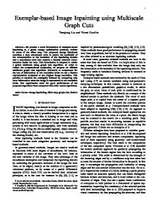
Inpainting is the art of restoring lost parts of an image and reconstructing them based on the background information. This has to be done in an undetectable way. The term inpainting is derived from the ancient art of restoring image by professional image restorers in museums etc. Digital Image Inpainting tries to imitate this process and perform the inpainting automatically. Figure 1 shows an example of this technique where a building (manually selected as the target region) is replaced by information from the remaining of the image in a visually plausible way. The algorithm automatically does this in a way that it looks “reasonable” to the human eye. Details that are hidden/ occluded completely by the object to be removed cannot be recovered by any mathematical method. Therefore the objective for image inpainting is not to recover the original image, but to create some image that has a close resemblance with the original image. Such software has several uses. One use is in restoring photographs. Ages ago, people were preserving their visual works carefully. With time, photographs get damaged and scratched. Users can then use the software to remove the cracks from the photographs.
(a)
(b)
Figure 1. Removing objects using Image Inpainting. (a) The original image [15], (b) Image with the building removed. Notice how the contour of mountain and the textures have both been corrected.
Another use of image inpainting is in creating special effects by removing unwanted objects from the image. Unwanted objects may range from microphones, ropes, some unwanted person and logos, stamped dates and text etc. in the image. During the transmission of images over a network, there may be some parts of an image that are missing. These parts can then be reconstructed using image inpainting. There have also been a few researches on how to use image inpainting for super-resolution and zooming of images [6]. The rest of the paper is organized as follows. Section 2 describes the related work in this area. Section 3 presents key observations and shortcomings of the earlier approaches. This is followed by a description of what we propose to improve the inpainting process. Experimental results and Conclusion & Future work then follow in sections 4 and 5 respectively. II.
RELATED WORK
Currently there are very few accepted technologies/tools for carrying out the work of image inpainting. It is still in the beginning stage and a lot of researches are being carried out to explore this area. There are, however, a few software products and libraries existing for this purpose. E.g. „restoreInpaint‟ [12] is an open source library which provides functionalities to detect and automatically restore
cracks etc. from damaged photographs. Software currently available for this task is named „Photo-Wipe‟ [11] by Hanov Solutions. It provides tools for selecting the region to be inpainted and then provides several options to carry out the inpainting process with varying time and quality. The algorithm at first sight may seem to be something similar to noise removal from images. De-noising is focused towards modifying individual pixels whereas inpainting aims at modifying larger regions from the image. Denoising also differs from inpainting in the way that in inpainting there is no information about the image in the region to be inpainted as opposed to noise removal where pixels may contain information about both the real data and noise [1]. Also, noise removal will in general not work for filling-in large missing portions in an image (e.g., in removal of an object). Thus specific methods are being developed to answer this problem. Most inpainting methods work as follows: The user selects the region to be inpainted. This is usually done as a separate process and may require the use of separate image processing tools. The image restoration is then carried out automatically. In order to produce a visually plausible reconstruction, an inpainting technique must try to reconstruct the isophotes (i.e. the lines of equal grey values) as smoothly as possible and also propagate two dimensional textures. Based on these two requirements, the inpainting algorithms are classified as in the following way. There are mainly three classes of algorithms employed for inpainting. First class of algorithms is for restoring films/videos, but this is not very useful for image inpainting as there is limited information for inpainting images as opposed to film inpainting where the information may be extracted from various frames. Another class of algorithms deals with the reconstruction of textures from the image (e.g. [4]). These algorithms utilize samples from the source region to rebuild the image. Using this approach, most of the texture of the image can be rebuilt. The third class of algorithms tries to rebuild the structural features such as edges and object contours etc. The authors of paper [1] presented a pioneering work in this respect. It was able to recover most of the structural features from the image but failed while recovering very large regions. Another algorithm proposed in paper [10] involved the use of mask to achieve inpainting. The mask that they choose for inpainting is decided interactively and requires user intervention. They prepare the mask such that the centre element in the mask is zero. This means that no information about a pixel is extracted using its own value (as it is the one that is to be reconstructed and in image inpainting, it is assumed that the region to be inpainted does not contain any information). It uses the values of its neighboring pixels to determine its value. But this algorithm also works only for small regions and cannot inpaint large regions in the image. Another algorithm for recovering small regions and noise in an image is proposed in paper [5]. It can inpaint images with very high noise ratio. It uses Cellular Neural Networks
for the same. Here noises inside the cell with different sizes are inpainted with different levels of surrounding information. They achieved a high accuracy in the field of de-noising using inpainting techniques. They provide results that show that an almost blurred image can be recovered with visually good effect. But as with other de-noising algorithms, the approach doesn‟t work well for large regions. The authors of paper [13] propose an algorithm using Cahn-Hilliard fourth order reaction equation to achieve inpainting in gray-scale images. The paper [2] extends the earlier mentioned paper [13] by introducing a total-variation flow for images. Authors in [4] proposed an inpainting algorithm to fill in holes in overlapping texture and/or cartoon image synthesis. Their algorithm is a direct extension of morphological component analysis that is designed to separate linearly combined texture and cartoon. Their approach differs from the one proposed by Bertalmio et al. [1]. On one hand, Bertalmio considered decomposition and filling-in stage as two blocks. On the other hand, their approach [4] considers these as one unified task. There have been a very few algorithms that utilize the advantages of both the image inpainting methods i.e. the structure recreation and texture synthesis algorithms. One such work was proposed in the paper by Criminisi et al. [3]. They proposed a pioneering approach in this field that combined structural reconstruction approach with the texture synthesis approach in one algorithm by combining the advantages of both approaches. They used the fact that the result of inpainting process depends (in general) on the order of filling-in the hole. The traditional concentric-layer filling (onion-peel) algorithm [17] for defining the region filling order failed to reconstruct structural features. On the other hand, they based their approach on the priority of regions which was based on the isophotes values and it allowed for the patches with the isophotes flowing into the patch to be filled earlier. Another approach proposed in [18] tries to improve the time complexity by defining a measure of step length for the search region. There is also significant work carried out in the field of video inpainting. The authors in [14] proposed an algorithm for video inpainting by implanting objects from other frames. They employ improved exemplar based algorithms for the same. Another approach for video inpainting employs information from adjacent frames and performs interpolation based on those frames to achieve inpainting [9]. Authors in [7] present an algorithm to inpaint videos using the exemplar based approach. They focus their research towards the restoration of old movies, and particularly scratch removal. They use the block based exemplar based approach and extend it using motion estimation. In this paper, we propose an extension to earlier inpainting algorithms with a focus on improving the
computational complexity of the approaches along with some other improvements such as speed and accuracy. III.
P(p) = C(p) x D(p) .
METHODOLOGY
The conventions that we use throughout the paper are similar to earlier papers that deal with this problem of image inpainting [1], [3], [10]. Here, I represents the original image. Ω represents the target region, i.e. the region to be inpainted. Φ represents the source region, i.e. the region from which information is available to reconstruct the image. Generally, Φ = I – Ω. Also, we use δΩ to represent the boundary of the target region, i.e. the fill front. It is from here that we find some patch that is to be filled. Our algorithm is basically an extension to the algorithm proposed by Criminisi et al. [3]. Using this algorithm, we can inpaint large missing regions in an image as well as reconstruct small defects. Generally an exemplar based inpainting algorithm involves the following steps: i. Initialize the target region. This is generally performed separately from the inpainting process and requires the use of an additional image processing tool. This is performed by marking the target region in some special colour. Without any loss of generality, let us consider that the colour that the target region will be marked in is green (i.e. R = 0, G = 255, B = 0). ii. Find the boundary of the target region. iii. Select a patch from the region to be inpainted. The patch size should be a bit larger than the largest distinguishable texture element in the image. We have used a default patch size of 9 x 9 which can be changed with the knowledge of the largest texture element in the image. We denote the patch by ψp. iv. Find a patch from the image which best matches the selected patch, ψp. This matching can be done using a suitable error metric. We use the Mean Squared Error (please refer eq. 1) to find the best matching patch. ∑
v.
In Criminisi‟s algorithm, the priority function used for selecting the best patch from the target region was defined in a multiplicative form (please refer eq. 2).
(
)
.
(1)
where fx,y represents the element of the patch ψp and gx,y represents the elements of the patch for which MSE is to be calculated. N is the total number of elements in the patch. Update the image information according to the patch found in the previous step.
As mentioned earlier, the result does depend considerably on the third step wherein a patch is selected to be inpainted. The result that we obtain would almost always depend on the selection order and thus there have been approaches that try to define this selection order so that the result is improved.
(2)
where C(p) represents the confidence term for the patch and D(p) the data term for the patch. These terms are defined in equations 3 and 4 respectively. ∑
( )
( )
( )
.
(3) (4)
.
where |ψp| is the area of the patch ψp and γ is the normalization factor (equal to 255 for a normal grey level image), np is a unit vector orthogonal to the front δΩ at the point p and represents the perpendicular isophote at point p. The value of np is found by finding the gradient for the source region. The source region represents a matrix with all ones on the points that are not in the target region and zeros otherwise (i.e. for the points in Ω). Isophote can be determined using the gradient of the image. Cheng et al. [16] discovered that the confidence term that was defined in Criminisi‟s algorithm decreases exponentially and thus the multiplicative definition of the priority term needs to be replaced. They also proposed that the confidence term in the additive form of priority did not match the order of the data term. Thus they modified the confidence term with the regularized confidence term. Also, the authors proposed the addition of weights to different components in the definition of priority term so that a balance between confidence and data term could be maintained. Thus the modified priority term can now be represented as (please refer eq. 5) ( )
( )
( ), 0 ≤ α, β ≤ 1 .
(5)
where α and β are respectively the component weights for the confidence and data terms. Also α + β = 1 and Rc(p) is the regularized confidence term (please refer eq. 6). ( )
(
)
( )
, 0 ≤ ω ≤ 1.
(6)
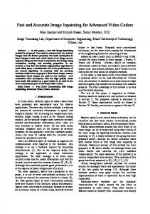
where ω is regularizing factor for controlling the curve smoothness. Using this confidence term the value of the confidence term is regularized to [ω,1]. In this way the new priority function will be able to resist the “dropping effect”. Now, as we have the priorities for the patches on the fill front, we can find the patch with maximum priority and select it as the patch that is to be inpainted. Let us call it ψp. The next step in the inpainting process is to find the patch with the maximum similarity with the selected patch. In the earlier approaches, the metric used for finding the similarity was the mean squared error. But none of them defines what is to be done when we have 2 (or more) patches with the
same mean squared error (See Figure 2). We found that in such cases, for some images, the algorithm produced visually poor results.
Figure 2. Patches with same mean square error. Selecting the incorrect patch may not produce the most visually plausigble result.
The solution to the problem that we propose involves the calculation of variance of the patches with same mean squared error. This variance (please refer eq. 8) that we use is the variance of the pixel values of the patch with respect to the mean (please refer eq. 7) of the pixels from the same patch that correspond to the pixels belonging to source region from the patch to be inpainted (i.e. pixels that correspond to ). ∑ * ∑( *
+
(7)
+
(8)
)
where „f‟ denotes the pixel value of the element, #{..} represents the cardinality of the set. Another improvement that we propose to the given approach is that Criminisi‟s approach looked for the best exemplar from the complete image. Most often, the patch that most resembles the selected patch lies very close to the patch selected to be inpainted. Based on this assumption, we provide an approach on how to reduce the computational complexity of the algorithm. The diameter of the surrounding region to search is calculated at run time by taking into account the region to be inpainted. We search for the best exemplar from a rectangle defined by (startX, startY) and (endX, endY). We can find these coordinates by using the maximum number of continuous green pixels in one row as well as a column. Let us assume that these values as cr and cc respectively. Then, we calculate the coordinates as follows.
(
).
(9)
(
).
(10)
(
).
(11)
(
).
(12)
Where h and w are height and width of the image respectively, m and n are number of rows and columns in the patch and Dx and Dy are constants that represent the minimum diameter for the X and Y directions respectively. These calculations ensure that there is at least one patch of the desired size with none of its pixels that belong to the target region (Ω). Doing these calculations every time we look for a patch will not deteriorate the performance of the algorithm as these calculations allow the algorithm to ignore quite a large number of patches. IV.
EXPERIMENTAL RESULTS
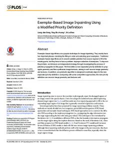
To verify the effectiveness of the proposed variance approach and the improvement in speed, we performed tests on several images and compared the so-obtained results with the conventional approaches. Several of the images that we present here are taken from the previous literature and we cite the appropriate paper wherever possible. In most of the experiments, the patch size was set to 9 x 9. We will state appropriately wherever a different patch size was taken by us and the reasons for the difference. A. Comparison with Criminisi’s approach [3] Now we present the comparison of our approach with the one presented by Criminisi et al. in [3]. The image in Figure 3 (a) was given as input to the inpainting process that used our approach as well as to our implementation of the Criminisi‟s approach. The results using Criminisi‟s approach were not that promising whereas our algorithm achieved better results. The difference in the results occurred while searching for the best exemplar patch. In Criminisi‟s approach, nothing is described about which patch to select if we get two patches with same minimum error. During our implementation of Criminisi‟s algorithm, we assumed that we would choose the patch that was found earlier and got the results as shown. Using our approach, however, the best exemplar process was well defined and therefore it selected a better patch as shown in Figure 3.
addition to this, the time would be less if the user selects small but spatially disconnected regions rather than if he selects the same percentage of target region continuously. This is so because we have taken into consideration the number of continuous green (color of the target region) pixels to remove the possibility of finding regions with no available patches.
(a)
(b)
(c)
Figure 3. Comparison with Criminisi‟s approach. (a) Image to be inpainted, (b) Result using our algorithm, (c) Result using our implementation of Criminisi‟s approach.
C. Comparison with Photo Wipe © [11] Now we present a comparison of our algorithm with the current existing software for the same task (Photo Wipe by Hanov Solutions). Figure 6 shows the results for the same (It is apparent that our algorithm produces better results).
B. Comparison on the basis of time with Criminisi’s aaproach Using the proposed fast inpainting algorithm, the time taken in inpainting the image is considerably reduced.
(a)
(a)
(b)
(b)
(c) Figure 5. Comparison with Photo Wipe. (a) The photograph in front of CC1, IIIT Allahabad. (b) Output from our algorithm. (c) Output using Photo Wipe‟s Full Quality Inpainting option.
(c) Figure 4. Comparison with Criminisi‟s approach on benchmark data. (a) Image to be inpainted [3]. (b) Result using our algorithm. (c) Result using our implementation of Criminisi‟s approach.
Following (Table 1) is a brief comparison of time taken using our approach and our implementation of Criminisi‟s approach. TABLE I.
COMPARISON OF OUR ALGORITHM IMPLEMENTATION OF CRIMINISI‟S ALGORITHM Serial No.
1. 2. 3. 4. 5.
AGAINST
OUR
Image Size Percentage area to Time taken (in pixels) be removed milliseconds)
124032 60492 120000 60492 225000
0.81 2.80 5.00 14.62 60.79
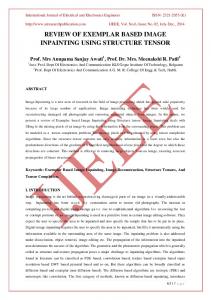
D. Real Life Examples Now we present a few more examples from real life scenes which are captured by us. Figure 6 shows an example of noise removal using our algorithm. The noise was added randomly to the image and then the inpainting was applied. The inpainting algorithm was able to achieve a good overall result than that achieved by applying median filter [8] on the image.
Criminisi
Our Algorithm
11223 11546 53971 61286 1357690
2283 4042 27319 52378 1337850
(in
Thus the total time using our algorithm obviously depends on how much area is selected to be inpainted. In
(a)
(b)
retaining the quality of inpainting and if possible, we would also like to improve the inpainting algorithm. Also the inpainting algorithm presented here is not meant to be used for inpainting videos. We are also investing methods to improve the proposed algorithm to make it more robust so that it can be used with videos. ACKNOWLEDGMENT We would like to thank our Director Dr. M.D. Tiwari for providing excellent computational facilities and stimulating work environment for carrying out the research work.
(c) Figure 6. Using inpainting to remove noise from the image. (a) Image with noise. (b) Result after applying our inpainting algorithm. (c) Result after applying 3x3 median filter on the image.
Now we present an example of removing an unwanted person from the photograph (See Figure 7).
REFERENCES [1]
[2]
[3]
[4]
[5]
[6] [7]
(a)
(b)
Figure 7. Example of removing unwanted persons. (a) The original image of IIIT Allahabad admin building with unwanted persons. (b) Image with the unwanted persons removed.
V.
CONCLUSION AND FUTURE WORK
We present an algorithm that can remove objects from the image in a way that it seems reasonable to the human eye. It can also restore old photographs (e.g. removal of scratches). Our approach extends an exemplar based inpainting method along with a priority term that defines the filling order in the image. In this algorithm, pixels maintain a confidence value and are chosen based on their priority that is calculated using confidence and data term. The approach defines a way of differentiating between patches that have the same minimum mean squared error with the selected patch. This approach is capable of propagating both linear structures and two dimensional textures into the target region. This technique can be used to fill small scratches in the image/photos as well as to remove larger objects from them. It is also computationally efficient and works well with larger images. We are looking forward to improving the algorithm so that the computational complexity is further improved while
[8] [9]
[10]
[11] [12] [13]
[14]
[15] [16]
[17]
[18]
M. Bertalmio, G. Saprio, V. Caselles, and C. Ballester, “Image Inpainting,” Proceedings of the 27th annual conference on Computer graphics and interactive technique, 417-424, 2000. M. Burger, H. Lin, and C.B. Schonlieb, “Cahn-Hilliard Inpainting and a Generalization for Grayvalue Images,” UCLA CAM report, 08-41, 2008. A. Criminisi, P. Perez, and K. Toyama, “Region Filling and Object Removal by Exemplar- Based Image Inpainting,” IEEE Transactions on Image Processing, 13(9), 1200-1212, 2004. M. Elad, J.L. Starck, P. Querre, and D.L. Donoho, “Simultaneous Cartoon and texture image inpainting using morphological component analysis (MCA) ,” Journal on Applied and Computational Harmonic Analysis, 340-358, 2005. P. Elango, and K. Murugesan, K, “Digital Image Inpainting Using Cellular Neural Network,” Int. J. Open Problems Compt. Math., 2(3), 439-450, 2009. M.J. Fadili, J.–L Starck, and F. Murtagh, “Inpainting and zooming using Sparse Representations,” The Computer Journal, 64-79, 2009. G. Forbin, B. Besserer, J. Boldys, and D. Tschumperle, “Temporal Extension to Exemplar- Based Inpainting applied to scratch correction in damaged image sequences,” Proceedings of the International Conference on Visualization, Imaging and Image Processing (VIIP 2005), Benidorm, Espange, , 1-5, 2005. R.C. Gonzalez, and R.E. Woods, Digital Image Processing, 2nd ed. Pearson Education, 2002. A.C. Kokaram, R.D. Morris, W.J. Fitzgerald, and P.J.W. Rayner, “Interpolation of missing data in image sequences,” IEEE Transactions on Image Processing 11(4), 1509-1519, 1995. M.M. Oliveira, B. Bowen, R. McKenna, and Y.S. Chang, “Fast Digital Image Inpainting,” Proceedings of the International Conference on Visualization, Imaging and Image Processing (VIIP 2001), Marbella, Spain, 261-266, 2001. Photo Wipe, http://www.hanovsolutions.com/?prod=PhotoWipe Restore Inpaint, http://restoreinpaint.sourceforge.net/ C.B. Schonlieb, A. Bertozzi, M. Burger, and H. Lin, “Image Inpainting Using a Fourth-Order Total Variation Flow,” SAMPTA‟09, Marseille, France, 2009. T. Shih, et al., “Video inpainting and implant via diversified temporal continuations,” Proceedings of the 14th annual ACM international conference on Multimedia, 133-136, 2006. Studio Lighting, http://www.studiolighting.net/ Wen-Huang Cheng, Chun-Wei Hsieh, Sheng-Kai Lin, Chia-Wei Wang, and Ja-Ling Wu, “Robust Algorithm for Exemplar-Based Image Inpainting,” The International Conference on Computer Graphics, Imaging and Vision (CGIV 2005), Beijing, China, 64-69, 2005. A. A. Efros and T. K. Leung, “Texture synthesis by nonparametric sampling,” Proceedings of IEEE International Conference on Computer Vision, Greece, 1033-1038, 1999. Q. Chen, Y. Zhang and Y. Liu, “Image Inpainting With Improved Exemplar-Based Approach,” Multimedia Content Analysis and Mining, LNCS, vol. 4577/2007, pp.242-251, 2007