February 2001
•
NREL/CP-500-28848
FAST_AD Code Verification: A Comparison to ADAMS
M.L. Buhl, Jr., A.D. Wright, and K.G. Pierce Presented at the 20th American Society of Mechanical Engineers (ASME) Wind Energy Symposium Reno, Nevada January 8-11, 2001
National Renewable Energy Laboratory 1617 Cole Boulevard Golden, Colorado 80401-3393 NREL is a U.S. Department of Energy Laboratory Operated by Midwest Research Institute • Battelle • Bechtel Contract No. DE-AC36-99-GO10337
NOTICE The submitted manuscript has been offered by an employee of the Midwest Research Institute (MRI), a contractor of the US Government under Contract No. DE-AC36-99GO10337. Accordingly, the US Government and MRI retain a nonexclusive royalty-free license to publish or reproduce the published form of this contribution, or allow others to do so, for US Government purposes. This report was prepared as an account of work sponsored by an agency of the United States government. Neither the United States government nor any agency thereof, nor any of their employees, makes any warranty, express or implied, or assumes any legal liability or responsibility for the accuracy, completeness, or usefulness of any information, apparatus, product, or process disclosed, or represents that its use would not infringe privately owned rights. Reference herein to any specific commercial product, process, or service by trade name, trademark, manufacturer, or otherwise does not necessarily constitute or imply its endorsement, recommendation, or favoring by the United States government or any agency thereof. The views and opinions of authors expressed herein do not necessarily state or reflect those of the United States government or any agency thereof. Available electronically at http://www.doe.gov/bridge
Available for a processing fee to U.S. Department of Energy and its contractors, in paper, from: U.S. Department of Energy Office of Scientific and Technical Information P.O. Box 62 Oak Ridge, TN 37831-0062 phone: 865.576.8401 fax: 865.576.5728 email:
[email protected] Available for sale to the public, in paper, from: U.S. Department of Commerce National Technical Information Service 5285 Port Royal Road Springfield, VA 22161 phone: 800.553.6847 fax: 703.605.6900 email:
[email protected] online ordering: http://www.ntis.gov/ordering.htm
Printed on paper containing at least 50% wastepaper, including 20% postconsumer waste
FAST_AD CODE VERIFICATION: A COMPARISON TO ADAMS Marshall L. Buhl, Jr. Member of ASME Senior Engineer I Alan D. Wright Senior Engineer II Kirk G. Pierce Member of AIAA Engineer II National Renewable Energy Laboratory Golden, CO ABSTRACT
both the extreme loads and the fatigue life of their turbines, the codes must be rigorously tested before they will be accepted by certifying agencies.
The National Renewable Energy Laboratory’s National Wind Technology Center (NWTC) has refocused its wind-turbine design-code comparison effort to verify FAST_AD with ADAMS®. FAST_AD is a wind-turbine structural-response code developed by Oregon State University for the NWTC. ADAMS is a commercial, general-purpose, multibody-dynamics code developed by Mechanical Dynamics, Inc. ADAMS, which is used in many industries, has been rigorously tested.1,2,3,4 Both ADAMS and FAST_AD use the AeroDyn subroutine package for calculating aerodynamic forces. The University of Utah developed AeroDyn for the NWTC. To compare FAST_AD to ADAMS, we modeled a rough approximation of the AWT–27 P4 turbine, using the same properties for both simulators. The AWT–27 is a 275-kilowatt (kW), two-bladed wind turbine. We also created three-bladed versions of the turbine models to verify FAST_AD for three-bladed turbines. In this paper, we list the aerodynamic features used in the comparison. We also explain how the programs model the turbine structure, describe the degrees of freedom (DOFs) used for this study, and present simulation comparisons that show very good agreement.
One of the first steps in ensuring the quality of these predictive codes is to compare them to hand calculations and to programs that have gained acceptance. The focus of this paper is on a comparison between the well-tested ADAMS1,2,3,4 code and the new FAST_AD5 code. ADAMS is a commercial, multibody-dynamics code developed by Mechanical Dynamics, Inc. FAST_AD is an aero-elastic code developed by Oregon State University and the University of Utah for the National Renewable Energy Laboratory’s (NREL's) National Wind Technology Center (NWTC). Both codes use the University of Utah’s AeroDyn6 subroutine package for calculating aerodynamic forces. In previous, less detailed comparisons7,8 between the ADAMS, FAST_AD, BLADED,* YawDyn,† and WT_Perf* design codes, we compared not only the structural response, but also the aerodynamic forces. Because of the differences in the aerodynamic models, it was difficult to compare the structural responses of the codes. We had no way to tell if the differences we saw in the structural responses were caused by the aerodynamic loads or the structural models. In the current study, it
INTRODUCTION The U.S. Department of Energy’s Wind Energy Program has developed several wind-turbine design codes. Although manufacturers can use these codes to predict
* BLADED is a commercial, wind-turbine, aero-elastic code from Garrad Hassan and Partners Limited, Bristol, England. † YawDyn is a wind-turbine, aero-elastic code developed at the University of Utah for the NWTC. It uses the AeroDyn subroutine set to generate aerodynamic loads. * WT_Perf is a wind-turbine performance code developed at the NWTC.
This material is declared a work of the U.S. Government and is not subject to copyright protection in the United States.
1
was easier to compare the structural responses because both ADAMS and FAST_AD use the same aerodynamic routines.
Both simulators use the AeroDyn aerodynamics subroutine package developed for the NWTC by the University of Utah. AeroDyn was written in a modular form that allows it to be readily interfaced to structuraldynamics codes. It can read hub-height wind files with wind shear and gusts. It can also read full-field turbulence files created by SNLWIND-3D, but we did not use this feature in this phase of our studies. AeroDyn uses blade-element momentum theory, a Pitt and Peters’ dynamic inflow model, and a LeishmanBeddoes dynamic stall model.
We modeled an approximation of the AWT–27 P4 turbine using both ADAMS and FAST_AD. The AWT–27 is a 275-kilowatt (kW), two-bladed, teetering, free-yaw, downwind turbine with 7° of precone. Because we did not compare predictions to test data for this study, it was far more important to use the same properties for both simulators than to accurately model the real turbine. Although the properties used were not quite the same as those of the AWT–27, they were close enough to represent a realistic, utility-scale wind turbine. We also modeled a three-bladed version of the turbine to test the three-bladed sections of FAST_AD.
ADAMS is a sophisticated program that can model virtually any type of turbine. It is not a wind-turbinespecific code and is often used to analyze cars, robots, and spacecraft. It is a well-tested program, and we believe the rigid-body predictions of this fully nonlinear code are very accurate. ADAMS uses lumped masses connected by flexible fields similar to multidimensional spring dampers to model flexible blades and towers. The flexible fields use some approximations and are not as exact as the rigid-body portion of the simulator. For our AWT–27 model, we used 11 lumped masses for each blade separated by 10 flexible field statements. For the tower, we used 9 lumped masses separated by 8 fields.
We used a range of steady winds and, except for shutdown, used a constant wind direction of 30°. For fixed-yaw cases, we used a yaw setting of 15°, which resulted in a net yaw error of 15°. For each of the inflow cases, we used the simulators to predict the structural response. Starting with a rigid turbine, we added new DOFs in steps until we were using fully flexible rotors and towers, free teeter and yaw, a shaft torsional spring, and an induction generator. We also tested shutdown maneuvers for the case of a rigid turbine with a torsional shaft spring, brake, and generator.
Unlike ADAMS, FAST_AD is a wind-turbine-specific code. Because of that, it has limited DOFs but can model many common turbine configurations. FAST_AD models flexible elements using modal representation. The reliability of this representation depends on the generation of accurate mode shapes, which are input into FAST_AD. We used a program called Modes to generate these shapes. Modes10 originally came with FAST_AD from Oregon State University, but we rewrote most of it at the NWTC. The blade and tower models also use properties such as stiffness and mass per unit length to specify the flexibility characteristics.
To compare the responses for steady conditions and compute azimuth averages, we used an NWTCdeveloped postprocessing program called Crunch9. For shutdown maneuvers, we compared time histories. In this paper, we list the aerodynamic features used in the programs, explain how the various programs model the turbine structure, describe the DOFs used for this study, and show some of the results. SIMULATOR CAPABILITIES ADAMS and FAST_AD use somewhat different techniques to model the turbine structure. For this comparison, we created ADAMS models that duplicated the DOFs available in FAST_AD. We excluded capabilities of ADAMS that are not available in FAST_AD, such as shaft bending and blade torsion. A list of programs and the versions we used appears in Table 1.
Because it is easier to convert from mass/length distributions to lumped masses, we derived the ADAMS properties from the distributions we used for FAST_AD. For this, we used an Excel spreadsheet to calculate the mass and centers of mass for the lumpedmass parts. AERODYNAMICS
Table 1. Simulator Versions Used in This Study. Program
Version
ADAMS
9.1 (Patch 91-40), AeroDyn 11.35
FAST_AD
2.20mlb-c (alpha), AeroDyn 11.35
In our previous comparisons,7 we used a special version of AeroDyn that we hoped mimicked the algorithms in Garrad Hassan’s BLADED for Windows. For this comparison, we used the distributed version of AeroDyn in place of the one we used to mimic BLADED.
2
For two-bladed turbines, we also modeled the teetering DOF. We did not, however, model teeter dampers with a typical dead band or with teeter stops. We put a light spring (1 kN·m/rad) on the teeter and enough damping (40 kN·m·s/rad) to get the models to behave in a vacuum. Unlike normal teeter systems, there is no freeteeter range—the spring is always engaged.
Because the thrust of this phase of our study was to compare the structural responses of the simulators, and because both codes use the same aerodynamic subroutines, we did not put much effort into comparing the aerodynamic loads. Because the codes have their aerodynamic stations at different locations, there were slight differences in the aerodynamic loads. This was probably most significant near the blade tip where the aerodynamic properties change rapidly with blade station. We think some of the differences we found in the structural responses were caused by the differences in aerodynamic stations. We used the same aerodynamic features for both codes: axial induction, tangential induction, equilibrium inflow, Prandtl tip loss, tower shadow, and wind shear.
Because of a lack of time and insufficient interest, we did not test the nacelle-pitch DOF available for twobladed turbines in FAST_AD. There is little interest in the wind industry for turbines with nacelles that are free to pitch. We also did not run any start-up cases. Because of the unusual way we start our ADAMS simulation (all blades collocated at the start), it is meaningless to compare the two codes. If we had a more normal ADAMS model, we could have done it. With the exception of these two cases, we tested all of FAST_AD’s available DOFs.
STRUCTURAL DEGREES OF FREEDOM We used various DOFs in different combinations, adding them one at a time to help resolve any differences that might arise. This helped us debug and fix various features of the FAST_AD code and model. Although we found no errors in the ADAMS code, we did find modeling errors. We also found that we had to adjust the integrations parameters for ADAMS for some combinations of DOFs. Without a comparison to FAST_AD, we may not have known that the integration parameters needed tuning and would have produced incorrect results. This provides a very strong incentive to simulate turbines with more than one code when doing design or analysis work.
MODELING We built our ADAMS model in an unusual way that enabled us to quickly change configurations. To produce the ADAMS input file, we created a file that we filtered through the Fortran preprocessor (FPP) that came with our compiler. The FPP input file used variables for things such as the number of blades, the precone angle, and the DOFs that were enabled. The simulations started out with all the blades pointing straight up without precone or pitch. During the first 5 seconds of the simulations, the model reconfigured itself during the rotor spin-up so the blades were in their desired locations and orientations. This caused significant start-up transients—especially for cases that had free-yaw, teeter, and/or tower flexibility. We had to add special spring/dampers to the model to stabilize it during startup and then disabled the dampers after 5 seconds. Although this seems to have worked well, it required some trial and error to get it to work properly.
As we mentioned in the section describing the capabilities of the simulators, we modeled blade and tower flexibility in ADAMS as a series of lumped masses separated by flexible fields similar to spring dampers. FAST_AD uses the method of modal representation. We enabled two flap modes and one edge mode for the blades and two fore-aft modes and two side-to-side modes for the tower. We modeled low-speed-shaft (LSS) flexibility as a torsional spring damper, using 7200 kN·m/rad for the spring and 1 kN·m·s/rad for the damper. Other DOFs tested were free yaw and rotor speed through an induction-generator model.
Although we originally used a Thevenin equivalent circuit to model the induction generator with ADAMS, we decided to use equations similar to those used by FAST_AD. FAST_AD uses a simple model that approximates a Thevenin equivalent circuit with straight lines. The two methods were quite close, but we wanted to eliminate all possible modeling differences so that we could spot errors in FAST_AD more easily. We created the linear parameters by fitting lines to the Thevenin torque/speed curve using Microsoft Excel.
For power-production cases with fixed-yaw, we set the yaw angle to 15°, which, when combined with a 30° wind direction, yielded a net yaw error of 15°. We found in early tests that FAST_AD gave different results for no yaw with a wind offset than it did for no wind offset with a yaw angle. This was due to a bug in the code that is now fixed. By using non-zero values for both yaw angle and wind direction to yield a net yaw error, we exercised two sets of equations in FAST_AD. Therefore, we ran all fixed-yaw cases that way.
WIND CONDITIONS First, we operated the models in a vacuum. This helped us find errors in our models and in the
3
FAST_AD software. After we obtained good agreement for the zero air-density case, we used steady, sheared winds for the inflow. We sometimes debugged with unsheared flow, but for most cases, it was sheared. We used steady winds of 6, 12, and 18 meters per second (m/s), which provided a reasonable range of speeds for the purposes of this study. Except for the shutdown cases, we also set the wind direction to 30°.
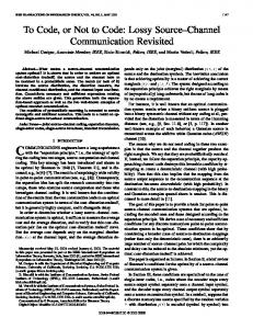
tower, flexible blades, a 15° fixed-yaw offset, and a rigid drive train running at constant speed in 18 m/s winds. The curves are virtually identical. Figure 1 is the only chart we will show of a comparison that we call virtually identical. In future references of comparisons that are virtually identical, we mean that the curves are this close. Figure 2 shows the blade loads for the same case. Although the agreement is excellent, they are not identical. The fine balance between blade loads produces the yaw moments shown in Figure 3. The agreement is quite good, but the differences in blade loads is magnified somewhat in the yaw moments. These small differences yield significantly different yaw angles (Figure 4), once the yaw lock is released, and the turbine is allowed to yaw freely.
DATA ANALYSIS Although we did not have time to test all appropriate output parameters, we did test some of the most important ones. Depending on the configuration, we compared: blade-root out-of-plane bending moment, in-plane (IP) bending moment, yaw moment, rotor torque, gearbox torque, teeter deflection, yaw angle, tower-top deflections, rotor speed, and gearbox speed. The gearbox parameters were for the gearbox end of the LSS.
Once we have a different equilibrium yaw angle, other parameters such as the teeter deflection (Figure 5) no longer track as well. This is an example of how small differences become magnified as DOFs are addedand the difficulty of accurately modeling a free-yaw turbine. If the yaw moments are only slightly wrong, the resulting error in yaw angle can produce very inaccurate vaues for other parameters in the simulation. Still, the blade loads for this case were quite close, as seen in Figure 6.
We usually ran 20-second simulations, disregarding the first 10 seconds to eliminate start-up transients, which were significant for ADAMS simulations. We usually ran free-yaw cases for 40 or 70 seconds, disregarding all but the last ten seconds of each of the simulations to make sure the yaw angle had stabilized. Sometimes, a modest difference in the equilibrium yaw angle caused a significant difference in loads, so we sometimes disabled the yaw DOF so that it would not mask smaller differences in the loads caused by differences in the models or algorithms.
At 12 m/s, the predictions for the free-yaw case are much closer. The equilibrium yaw angles were much closer and the teeter deflections and blade loads were virtually identical. As seen in Figure 7, the tower-top deflections differed by only 1 or 2 millimeters (mm). Our tower-top deflections are modeled with respect to the zero-yaw orientation of the turbine, and do not move with the nacelle. At 18 m/s, the tower fore-aft deflections were quite close, but the side-to-side deflections differed by 3–4 mm because of the difference in yaw angle. At 6 m/s, the tower-top deflections were virtually identical. For the fixed-yaw cases, all parameters agreed extremely well for all wind speeds.
We used Crunch v1.81 to generate azimuth averages of the signals for all but the shutdown cases, which we compared using time series. COMPARISONS As stated earlier, we started with a zero DOF turbine operating in a vacuum.* Because the codes agreed so well in that case that the curves were virtually identical, we will not show them here. We also added DOFs one at a time and debugged the models and software along the way. There is not space in a conference paper to show comparisons of all the parameters for all configurations, therefore, we will only show a representative selection.
When we tried running the two-bladed models with all DOFs enabled, the ADAMS model produced incorrect results. However, in later studies of the shutdown sequence, we found that the ADAMS integration parameters required tuning to get a “correct” solution. We did not have time to rerun all the normal production cases with tuned parameters, but expect that tuning the parameters will produce better results.
Two-Bladed Turbine in Power Production To illustrate the problems we had when the equilibrium yaw angles did not agree, we first show comparisons of the teeter deflection. Figure 1 shows the teeter deflection for the case for which we used a flexible
Three-Bladed Turbine in Power Production When we compared the two codes using models of three-bladed turbines, the results were similar to the comparisons of two-bladed turbines; the degree of
*
For all the cases we ran with zero air density and various DOFs, the results were virtually identical.
4
equations of motion more accurate, but we also tested and, if necessary, fixed many of the output quantities. As a result, we have greatly improved the quality, usability, and accuracy of FAST_AD.
agreement varied somewhat with wind speed. We also had what we suspect were integration problems with ADAMS when we enabled all DOFs. For our zero-DOF models, we obtained very good agreement between the codes. The blade loads differed slightly for all wind speeds, although the in-plane loads were virtually identical for the 6 and 12 m/s cases (Figure 8). Rotor torque was virtually identical for the 6 m/s case but differed as the wind speed increased. At 18 m/s, the torque responses differed by about 6% (see Figure 9). The error seems to be proportional to the level of torque, and FAST_AD always gave the highest value. The yaw moments differed by about 6% at 6 m/s but were very close at higher wind speeds.
The problems we had with the ADAMS integration parameters underscored the necessity of retesting the parameters as new features are added to a working model. It also showed the benefits of using more than one simulator to model a turbine. Had we not compared ADAMS to another code, we may never have realized that, although we were getting believable answers, the answers were wrong. CONCLUSIONS As a result of our study, it appears that the major features of FAST_AD have been thoroughly tested and are working well. There are still some differences, but we suspect they are largely due to the different ways the aerodynamic forces are applied to the blades. Neither technique is wrong. The codes just use different ways to approximate the distributed aerodynamic loading of the blades. We should be able to prove this hypothesis by showing that the differences lessen with an increase in the number of blade stations. This may be a useful future exercise.
When we turned on all DOFs except free yaw, we still had very good agreement between the codes. The only time ADAMS showed a strong tower-shadow effect was at 18 m/s wind speed. We suspect this is due to the integration problems that seemed to arise when we added the torsional spring to account for shaft flexibility. Figure 10 shows a comparison of rotor torques at 12 m/s. When we turned on all DOFs, ADAMS produced incorrect results. Therefore, we will not show the results for that case. Although we know that we can probably get ADAMS to work correctly by tuning the integration parameters, we do not have the time nor funding to test the theory. Because FAST_AD behaved well for this configuration, we decided not to pursue the ADAMS problems.
We are very happy with the comparisons of the codes. Although the predictions sometimes differed slightly, the differences were tiny in light of the difficulty of obtaining accurate structural and aerodynamic properties. With a little more work, FAST_AD will be ready for release. We need to implement a few suggested changes, and we should add more cases to the automated verification test suite. A beta version of FAST_AD should be available for general release by the time this paper is published.
Shutdown Maneuvers We discovered the ADAMS integration problems when we tried to get it to operate correctly during the shutdown maneuver for the three-bladed turbine with a flexible drive train. After tuning ADAMS, we obtained virtually identical results between the codes for both two- and three-bladed turbines. We ran the maneuvers for both rigid and flexible drive trains. Figure 11 compares the rotor speed for both cases and Figure 12 compares the rotor torque. Without color, it is difficult to see the differences in rotor-speed chart in Figure 11, but there is a slight wiggle in the flexible-drive-train curves. In the rotor-torque chart in Figure 12, the flexible case produces large oscillations.
FUTURE WORK We tested only the output parameters that would tell us whether or not the equations of motion were correctly implemented. For example, we compared rotor torque but not rotor power. We would like to do a more thorough test of all the output parameters to ensure they are correctly coded. We also have a long wish list of improvements we would like to make to FAST_AD. Some would improve usability, some would simplify the coding, and others would make the algorithms more accurate. We want to check the coding efficiency to see if we can make it faster. We have already started to put in PID (proportional-integral-derivative) pitch control, and we would like to add new input and output parameters.
BENEFITS OF THE STUDY Our system of starting out with zero DOFs and then adding DOFs one at a time was essential to this study. It allowed us to find errors in our models and the FAST_AD code. Our study produced 23 different alpha versions of FAST_AD. Not only are the
5
We also want to fix some of the minor errors that we found but have not had time to fix.
5 Wilson, R.E.; Walker, S.N.; Heh, P. Technical and User’s Manual for the FAST_AD Advanced Dynamics Code. OSU/NREL Report 99–01. Corvallis, Oregon: Oregon State University, May 1999.
In addition, we should increase the number of input stations to see if we can lessen the remaining differences. This will require changes, possibly minor, to both AeroDyn and FAST_AD.
6 Hansen, A.C. User’s Guide to the Wind Turbine Dynamics Computer Programs YawDyn and AeroDyn for ADAMS®, Version 11.0. Salt Lake City, Utah: University of Utah, August 1998. Prepared for the National Renewable Energy Laboratory under Subcontract No. XAF-4-1407602.
ACKNOWLEDGEMENTS We would like to thank everyone who helped us with this study, including: Craig Hansen, Dave Laino, and Akihiro Suzuki of Windward Engineering for creating YawDyn and AeroDyn, for fixing the problems we found, and for helping us interface AeroDyn with FAST; Bob Wilson and Ping Heh from Oregon State University, from which FAST originated, for helping us debug FAST_AD in a timely fashion; Kathy O’Dell of NREL for making this paper much more readable.
7 Buhl Jr., M.L.; Wright, A.D.; Tangler, J.L. “Wind Turbine Design Codes: A Preliminary Comparison of the Aerodynamics.” Prepared for the 17th ASME Wind Energy Symposium, Reno, Nevada, January 12–15, 1998. NREL/CP-500-23975. Golden, Colorado: National Renewable Energy Laboratory, December 1997.
We would also like to thank all the managers at the U.S. Department of Energy and NREL who allowed us to do this study the right way. Had we not been allowed extra time to complete the study, we would not have been able to examine the codes with the meticulous detail required to find all the errors. And a special thanks to Robert Thresher, Sue Hock, Mike Robinson, Sandy Butterfield, and Alan Laxson. Without their support, these codes would not be as accurate as they are today.
8 Buhl Jr., M.L.; Wright, A.D.; Pierce, K.G. “Wind Turbine Design Codes: A Comparison of the Structural Response.” Presented at the 19th American Society of Mechanical Engineers (ASME) Wind Energy Symposium, Reno, Nevada, January 10–13, 2000. NREL/CP-500-27470. Golden, Colorado: National Renewable Energy Laboratory, February 2000.
This work was done at the National Renewable Energy Laboratory in support of the U.S. Department of Energy under contract number DC-AC36-98-GO10337.
9 Buhl Jr., M.L. “Crunch: A Batch-Oriented Postprocessor for Wind Turbine Data Analysis.” NWTC Design Codes, http://wind2.nrel.gov/designcodes/ crunch/. Last modified September 22, 2000; accessed September 26, 2000.
REFERENCES 1 Elliott, A.S.; McConville, J.B. (1989). “Application of a General-Purpose Mechanical Systems Analysis Code to Rotorcraft Dynamics Problems.” Prepared for the American Helicopter Society National Specialists’ Meeting on Rotorcraft Dynamics, 1989.
10 Buhl Jr., M.L. “A Simple Mode-Shape Generator for Both Towers and Rotating Blades.” NWTC Design Codes (Modes), http://wind2.nrel.gov/designcodes/ modes/. Last modified August 16, 2000; accessed September 26, 2000.
2 Elliott, A.S. (1989). “Analyzing Rotor Dynamics with a General-Purpose Code,” Mechanical Engineering 112, no. 12 (December 1990): pp. 21–25. 3 Malcolm, D.J.; Wright, A.W. “The Use of ADAMS to model the AWT-26 Prototype.” Wind Energy 1994. SED–Vol. 15. New York: American Society of Mechanical Engineers; pp. 125–131. 4 Ozdalyan, B.; Blundell, M.V.; Phillips, B. “Comparison of Suspension Rig Measurements with Computer Simulation.” Prepared for the International Conference on Simulation, September 30–October 2, 1998, York, United Kingdom. London, United Kingdom: IEE, 1998; pp. 133–139.
6
Teeter Deflection, degrees
6 4 ADAMS
2
FAST_AD
0 -2 -4 -6 0
90
180
270
360
Blade Azimuth, degrees
Blade Bending Moments, kN·m
Figure 1. A comparison of teeter deflection for a 2-bladed, teetering turbine with flexible blades and tower operating with a fixed yaw error of 15° in an 18 m/s steady wind. 150 100
Out-of-Plane Bending
50 0
ADAMS
-50
In-Plane Bending
FAST_AD
-100 0
90
180
270
360
Blade Azimuth, degrees Figure 2. A comparison of blade bending moments for a 2-bladed, teetering turbine with flexible blades and tower operating with a fixed yaw error of 15° in an 18 m/s steady wind.
Yaw Moments, kN·m
20 ADAMS
10
FAST_AD 0 -10 -20 0
90
180
270
360
Blade Azimuth, degrees Figure 3. A comparison of yaw moment for a 2-bladed, teetering turbine with flexible blades and tower operating with a fixed yaw error of 15° in an 18 m/s steady wind.
7
Yaw Angle, degrees
20 15 10 ADAMS
5
FAST_AD
0 0
90
180
270
360
Blade Azimuth, degrees
Teeter Deflection, degrees
Figure 4. A comparison of yaw angles for a 2-bladed, teetering turbine with flexible blades and tower operating with free yaw in an 18 m/s steady wind. 6 4 ADAMS
2
FAST_AD
0 -2 -4 -6 0
90
180
270
360
Blade Azimuth, degrees
Blade Bending Moments, kN·m
Figure 5. A comparison of teeter deflection for a 2-bladed, teetering turbine with flexible blades and tower operating with free yaw in an 18 m/s steady wind. 150 100
Out-of-Plane Bending
50 0
ADAMS
-50
In-Plane Bending
FAST_AD
-100 0
90
180
270
360
Blade Azimuth, degrees Figure 6. A comparison of blade bending moments for a 2-bladed, teetering turbine with flexible blades and tower operating with free yaw in an 18 m/s steady wind.
8
Tower-Top Deflections, cm
6 Fore-Aft Deflection
5 4 3 2
Side-to-Side Deflection
ADAMS
1
FAST_AD
0 0
90
180
270
360
Blade Azimuth, degrees
Blade Bending Moments, kN·m
Figure 7. A comparison of tower-top deflections for a 2-bladed, teetering turbine with flexible blades and tower operating with free yaw in a 12 m/s steady wind. 100 75
ADAMS FAST_AD
50 In-Plane Bending
25 0 -25
Out-of-Plane Bending
-50 0
90
180
270
360
Blade Azimuth, degrees Figure 8. A comparison of blade loads for a 3-bladed turbine with no degrees of freedom in a 6 m/s steady wind.
Rotor Torque, kN·m
100 80 60 40
ADAMS
20
FAST_AD
0 0
90
180
270
360
Blade Azimuth, degrees Figure 9. A comparison of rotor torques for a 3-bladed turbine with no degrees of freedom in an 18 m/s steady wind.
9
Rotor Torque, kN·m
100 ADAMS
80
FAST_AD
60 40 20 0 0
90
180
270
360
Blade Azimuth, degrees Figure 10. A comparison of rotor torques for a 3-bladed, fixed-yaw turbine with flexible blades, tower, and drive train in a 12 m/s steady wind.
Rotor Speed, rpm
80 60 ADAMS, Flex. DT
40
ADAMS, Rigid DT FAST_AD, Flex. DT
20
FAST_AD, Rigid DT 0 10
12
14
16
18
20
Time, seconds Figure 11. A comparison of rotor speeds for a 3-bladed, fixed-yaw turbine during a shutdown maneuver.
Rotor Torque, kN·m
150 ADAMS, Flex. DT
120
ADAMS, Rigid DT
90
FAST_AD, Flex. DT FAST_AD, Rigid DT
60 30 0 -30 10
12
14
Time, seconds
16
18
Figure 12. A comparison of rotor torques for a 3-bladed, fixed-yaw turbine during a shutdown maneuver.
10
20
Form Approved OMB NO. 0704-0188
REPORT DOCUMENTATION PAGE
Public reporting burden for this collection of information is estimated to average 1 hour per response, including the time for reviewing instructions, searching existing data sources, gathering and maintaining the data needed, and completing and reviewing the collection of information. Send comments regarding this burden estimate or any other aspect of this collection of information, including suggestions for reducing this burden, to Washington Headquarters Services, Directorate for Information Operations and Reports, 1215 Jefferson Davis Highway, Suite 1204, Arlington, VA 22202-4302, and to the Office of Management and Budget, Paperwork Reduction Project (0704-0188), Washington, DC 20503.
1. AGENCY USE ONLY (Leave blank)
2. REPORT DATE
February 2001
3. REPORT TYPE AND DATES COVERED
Conference Paper
4. TITLE AND SUBTITLE
5. FUNDING NUMBERS
FAST_AD Code Verification: A Comparison to ADAMS 6. AUTHOR(S)
WE002410
M.S. Buhl, Jr., A.D. Wright, and K.G. Pierce 7. PERFORMING ORGANIZATION NAME(S) AND ADDRESS(ES)
8. PERFORMING ORGANIZATION REPORT NUMBER
National Renewable Energy Laboratory 1617 Cole Blvd. Golden, CO 80401-3393
NREL/CP-500-28848
9. SPONSORING/MONITORING AGENCY NAME(S) AND ADDRESS(ES)
10. SPONSORING/MONITORING AGENCY REPORT NUMBER
11. SUPPLEMENTARY NOTES
NREL Technical Monitor: 12a.
DISTRIBUTION/AVAILABILITY STATEMENT
12b.
DISTRIBUTION CODE
National Technical Information Service U.S. Department of Commerce 5285 Port Royal Road Springfield, VA 22161 13. ABSTRACT (Maximum 200 words)
The National Renewable Energy Laboratory’s National Wind Technology Center (NWTC) has refocused its wind-turbine design-code comparison effort to verify FAST_AD with ADAMS®. FAST_AD is a wind-turbine structural-response code developed by Oregon State University for the NWTC. ADAMS is a commercial, general-purpose, multibody-dynamics code developed by Mechanical Dynamics, Inc. ADAMS, which is used in many industries, has been rigorously tested. Both ADAMS and FAST_AD use the AeroDyn subroutine package for calculating aerodynamic forces. The University of Utah developed AeroDyn for the NWTC. To compare FAST_AD to ADAMS, we modeled a rough approximation of the AWT–27 P4 turbine, using the same properties for both simulators. The AWT–27 is a 275-kilowatt (kW), two-bladed wind turbine. We also created three-bladed versions of the turbine models to verify FAST_AD for three-bladed turbines. In this paper, we list the aerodynamic features used in the comparison. We also explain how the programs model the turbine structure, describe the degrees of freedom (DOFs) used for this study, and present simulation comparisons that show very good agreement.
15. NUMBER OF PAGES
14. SUBJECT TERMS Wind energy; computer simulation design codes
16. PRICE CODE 17. SECURITY CLASSIFICATION OF REPORT
Unclassified NSN 7540-01-280-5500
18. SECURITY CLASSIFICATION OF THIS PAGE
Unclassified
19. SECURITY CLASSIFICATION OF ABSTRACT
Unclassified
20. LIMITATION OF ABSTRACT
UL Standard Form 298 (Rev. 2-89) Prescribed by ANSI Std. Z39-18 298-102