th
5 International Advanced Technologies Symposium (IATS’09), May 13-15, 2009, Karabuk, Turkey
FEATURE RECOGNITION AND DESIGN ADVISORY SYSTEM FOR SHEET METAL COMPONENTS Mohammad Ali Farsi a,* and Behrooz Arezoo b Islamic Azad University- Eghlid branch, Iran,
[email protected] b CAD/CAPP/CAM Research centre, Amirkabir University of Technology, Tehran, Iran,
[email protected] a, *
Abstract The present paper explains a feature recognition module and design advisor system for sheet metal components. In this system features of sheet metal components are extracted automatically from 3-D model. These data are modeled based on object oriented. The proposed system will aid the designer right at the design stage with useful design and manufacturability recommendations that have been gathered through years of experience. The system has been implemented in solid works 2008 using visual basic. Keywords: Feature recognition, Advisory system, Sheet metal.
1. Introduction Today, many products are made with sheet metal components. These products can be simple components requiring simple fabrication steps while others may involve very complicated processes requiring several steps to fabricate. For the complicated parts the time to market from conceptualization stage can be significantly shortened at various levels from design to manufacturing by understanding the product, its features and implications of the features [1]. It is widely accepted that about 70 percent of the final product cost is determined during the design stage [2]. Systems that automatically provide inputs on manufacturing guidelines to designers during the initial design process that lower costs and reduce cycle times have proven highly effective in achieving their goals. The sheet metal industry is largely an empirical industry. The design and process planning of sheet metal products need human involvement more than other areas of manufacturing industry. Design of complex parts are based heavily on human experience. In the design stage, if some of the design considerations are ignored, the cost of production may increase rapidly. To prevent modification attempts of the initial design from becoming a trial and error process, some knowledgebased assistance is necessary. If the traditional knowledge gained from years of experience is integrated into a solid modeler, it will provide valuable input to the designer. The designer can then attempt changes while adhering to the functional requirements of the design for achieving easier manufacture and reduced costs at the same time. Although, there have been attempts ([1], [3-[5]) to create a solution for these problems, most of them have been design rule checkers using a few design rules. Also, these systems only check for violations of certain constraints and do not suggest recommended practices where appropriate. A comprehensive design advisory system has not been attempted yet. The comprehensive
© IATS’09, Karabük University, Karabük, Turkey
approach should successfully encompass the design rules, standard manufacturing practices and design recommendations across all sheet metal processes and also investigate the interaction between these elements in the creation of a final sheet metal part.
2. Related works Nnaji et al. [1] have developed a set of principles for extracting features from sheet metal parts. In order to make the system generalized, the system developed requires B-Rep information about the sheet metal part in IGES neutral file format. Mantripragada et al. [5] have developed a feature based design system, which acts like an interactive design tool and can be used to alert designers for potential production problems, defects and failures. It also provides them with information that can be used to explore alternative designs, evaluate trade-offs and arrive at optimal design for the given process conditions. Jagirdar et al. [6] have proposed a feature recognition methodology for recognizing shearing operations for 2-D sheet metal components created by a wire-frame model. Yeh, et al. [7] described a feature based product modeler, Promod-S, which includes a rule-based design advisor among several other modules. In recent years, Shashikiran [8] designed an Advisory system for sheet metal components. This paper describes a new package for feature recognition and advisory system. The system uses 3-D solid model of sheet metal component as input. It also provides an advisory system to control the part and warn the user of any incorrect features in the component. The system also presents some comments for necessary modifications.
3. Feature Recognition The features that are basic to sheet metal parts are stamped and formed features. Stamped features are categorized as internal and external features. Internal features include features like round holes, square holes, rectangular holes, oblong holes, etc. External stamped features include different types of notches. The most widely formed features are bends and flanges. In the feature recognition module, all data used for the advisory system and a die designer system are extracted [9]. Data modeling methodology in this work is based on object oriented approach. For example, the following data are extracted from a bend feature: Bend radius Bend angle Length of each bend Bend height Bending direction
Farsi, M.A. and Arezoo, B.
Coordination of start, end and middle points on bend line Connected planes to bend Bend factor (it is used for unfolding calculations) Material type Material thickness
4. Design Considerations and Rules This section describes the rules for sheet metal component design. Most companies use their best practical knowledge for manufacturing in order to reduce infeasible designs, costs and production cycle times. However, this knowledge is treated as a trade secret and is not readily available. In this work, Design For Manufacturability (DFM) rules were extracted from metal forming fundamentals, Industry observations, Hand Books, DFM books. In the next sections, some of the design rules are discussed.
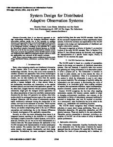
4.4 Triangular tabs or slots 1. Triangular tabs or slots should have a minimum end radii equal to the thickness and should form include angles of 60° or more. 2. Tapers for blanks should be recessed from the edge of the part at least as much as the thickness. 3. Components requiring round ends should have a radius greater than or equal to 0.75W as shown in Figure 2.
Fig. 2. Stock Radius [11]
4.1 Holes 1. The diameter of punched holes should be greater than the thickness of the work piece and not less than 2.5 mm. This is because the punch diameter becomes too small to bear the shear force required to punch the hole over a small area, often leading to failure. These small diameter holes are punched using the fineblanking processes. 2. Oblong holes: Oblong holes are generally incorporated as adjustment slots. As a general rule, the length to width ratio of an adjustment slot should be no more than 5 to 1. 3. Holes on faces which have angles greater than 30 degree should be avoided as far as possible. 4.2 Notches 1. Notches should have a width of no less than 1.5 the thickness and in any case no less than 0.50 mm. (Figure1) 2. The minimum widths of tabs and slots should be 1.5 times the thickness or 0.5 mm. Their length should be a maximum of 5 times their width. 3. For long narrow projections the minimum width of narrow sections should be 1.5 times the thickness.
4. 0.5 of W may be used if a relief angle 10° or greater at the point of tangency with the part edge is also used as shown in Figure 3.
Fig. 3. Stock Relief Angle [11] Following rules are applicable only for forming operations in sheet metal parts. 4.5 Beads 1. The maximum height for beads is 2 times the thickness. 2. The minimum inner radius for beads is equal to the thickness of the piece 4.6 Bends 1. The width along the bend axis should be greater than or equal to 3 times the thickness. 2. The bend radius (rb), rb >= C X t (t is thickness, C depends on the material). Table1 shows coefficient C for some of materials. 3. The short leg (inside length) should be greater than or equal to 2.5 times the thickness plus bending radius (figure 4)
Fig. 1. Notch and Tab guideline [10]
Fig. 4. Bend Height [10]
Farsi, M.A. and Arezoo, B.
Table1. Coefficient C in bending radius [12] Material Low carbon steel Low alloy steel Stainless steel Al Al alloy-2000 series Al alloy 3000 &4000 series Al alloy 5000 series Cu Brass
Annealed 0.5 0.5 0.5 0.0 1.5
Type Harden 3.0 4.0 4.0 1.2 6.0
0.8
3.0
1.0 0.25 0.4
5.0 4.0 2.0
3. Metal that is rolled shows grains along the direction in which the stock was drawn though the mill rolls. Bends should be at right angles to the grains or as close as possible to avoid breakage of the blank as shown in Figure 5. These factors must be considered while producing the blank and sometimes the most economical layout of the strip will have to be abandoned in order to avoid trouble in later forming operations. If the bends are at right angles, the blank should be diagonal to the grain.
recommended that this distance be at least 1.5 to 2 times the thickness of the work-piece. 3. The nearest edge of the hole to any bending tangent line should be at least 1.5 times the thickness plus radii of the bend. Distortion of the hole will occur if the features are any closer. 4. Slots that are parallel to the bend should be a minimum of 4 times the thickness from the bend tangent line. But slots and holes can be punched on the bend surfaces. 5. Sharp corners, which are stress concentration points, should be avoided wherever possible. Sharp external corners of punches and dies tend to break down prematurely, causing more pull-down, larger burrs, or rougher edges of the blanked part in the area of the corner. Similarly, sharp interior corners of punches and dies are a stress-concentration point and can lead to cracking and failure from heat treatment or in use. design guideline is to allow a minimum corner radius of two times the thickness and never less than 4 mm. 6. Adjacent tabs or slots should be spaced a minimum of 2 times the thickness or 0.8 mm apart. 7. Internal slots should be at least 1.5 times the thickness or 0.8 mm from the edge of the stock.
5. Feature Extraction and Design Advisor The system is implemented in visual Basic in solid works platform. The system extracts internal, external and bending features from solid model and saves their data in a file. Figure 5 shows schematic view of the system. In the next section the capabilities of the system is shown by an example.
6. Case Study
Fig. 5. Direction of rolling [8] In other words, bending operations perpendicular to rolling direction is easier than parallel to the rolling direction. Bending parallel to the rolling direction can often lead to fracture in hard materials. Hot rolled steel can be bent parallel to the rolling direction. So bends in each direction are calculated and the system suggests to the user suitable direction according to material type and number of bends in each direction. 4.7 Inter-feature Rules 1. The spacing between the holes should be at least 2 times the thickness and preferably 3 times to provide additional strength to the die, by allowing a greater wall thickness. However it should not be less than 1.5 mm 2. The minimum distance from the edge of the hole to the edge of any other feature should be greater than the thickness and not less than 0.8 mm. It is
Figure 6-a shows a part used in the Ghaleb Pishrafteh IRANKHODRO (GPI) company. This part has eight bends with several internal and external stamping features. Figure 6-b shows bend parameters for this part extracted by the system. These parameters include radius, angle and length of each bend and their connecting planes. Other parameters of the bend feature such as bending direction, coordination of the start and end points are exacted too. Also, parameters of circular holes, slots, notches and Dform cuttings are automatically extracted and are saved in a file.
Farsi , M .A and Arezoo, B.
Fig. 5. Schematic view of feature extraction and design advisory system
The advisory system uses features data extracted in the recognition module. The features data are saved in a file based on object oriented. Then these data controlled using DFM rules. In next paragraphs some of the advisory system outputs are described. The uncorrected features in model are high lighted by the system. Figure 7 shows the system out puts for bends and cutting features on the main plane of the part. According to this figure, slots feature are not correct and the circle radius is small, these features are high lighted. Also, the bends radiuses are small. These bends are highlighted by red color and they should be modified by the user. In this section the internal and external features on the each plane of part are checked separately; at the end bending features are controlled.
a-
For example in the main plane of the part, D-shape cutting feature is correct. Because, the feature sizes is suitable and more than 2 times the thickness in each direction [9]. Also, the distances between features are enough and more than 2 times the thickness. But the diameter of the hole is less than 2.5 mm ( it is 1.25mm) and the length to width ratio of the slots are more than 5 to 1 ratio ( in this example the ratio is 6.5). Also, according to material type (Harden Low carbon steel) minimum radius of the bends is 3 times the thickness (6 mm); but it is 0.737 mm. In this module, first, the system highlights incorrect features and then the advisory module's comments are presented to the user by a message box.
Sample part
Farsi, M.A. and Arezoo, B.
b- Bends parameters Fig. 6. Part and Bends parameters
a- Incorrect features on selected face
b- All bends have problem
Fig. 7. Features checked by DFM rules
7. Conclusion In this paper a feature recognizer and design advisory system is described. This system includes two modules: feature recognizer and a design for manufacturability module. The stamping and forming features can be recognized and extracted. Data modeling methodology in this work is based on object oriented approach. The system can recognize incorrect features and suggest some comments for editing the incorrect features. This system can be used as first stage of a progressive dies design system where the produced later be used for determining the operations sequencing and progressive die design. The system was evaluated using industrial sheet metal components.
References [1] Bartholomew O. Nnaji, Tzong-Shyan Kang, Shuchieh Yeh and Jang-Ping Chen, Feature reasoning for sheet metal components, International Journal of Production Research, Vol. 29, 1867-1896, 1991 . [2] J. R. Donovan and P. Dewhurst, A Preliminary analysis of DFM for Sheet Metal Parts using Pro-Engineer, Report #65, Department of Industrial and Manufacturing Engineering, University of Rhode Island, August 1988. [3] D. Zenger and P. Dewhurst, Early Assessment of Tooling Costs in the Design of Sheet Metal Parts, Report #29, Department of Industrial and
Manufacturing Engineering, University of Rhode Island, March 1993. [4] Donovan, James Ryan, A computer-aided cost estimating system for sheet metal parts, phd Thesis, Industrial and Manufacturing Engineering, University of Rhode Island, 1992. [5] R. Mantripragada, G. Kinzel, T. Altan, A computeraided engineering system for feature-based design of box-type sheet metal parts, Journal of Materials Processing Technology, vol. 57, 241-248, 1996. [6] Jagirdar R, Jain V. K, Batra J. L, Dhande S. G., Computer Integrated Manufacturing Systems, Vol. 8, 1, 51-62, 1995. [7] Yeh Shuchieh , Kamran Mehran , Terry Jules M. E and Nnaji B. O., A Design advisor for sheet metal fabrication, IIE Transactions (Institute of Industrial Engineers), Vol. 28, 1, 1-10, 1996. [8] Shashikiran Hegde, Design Advisory System – InterFeature Rules, M.S thesis, University of Cincinnati, 2003 [9] M. A. Farsi, Computer Aided Design of progressive bending die layout, Phd thesis, AmirKabir university of Technology, 2009 [10] Bralla, James G., Design for Manufacturability Handbook, McGraw-Hill, Newyork,1999
[11] www.efunda.com [12] V. Boljanovic, Sheet metal forming processes and die design, Industrial Perss, New York, 2004