240
JOURNAL OF MULTIMEDIA, VOL. 4, NO. 4, AUGUST 2009
Film Colorization Using Texture Feature Coding and Artificial Neural Networks Mina Koleini
Department of Computer Engineering, Faculty of Engineering, University of Isfahan, Isfahan, 81746, Iran Email:
[email protected]
S. Amirhassan Monadjemi
Department of Computer Engineering, Faculty of Engineering, University of Isfahan, Isfahan, 81746, Iran Email:
[email protected]
Payman Moallem
Department of Electrical Engineering, Faculty of Engineering, University of Isfahan, Isfahan, 81746, Iran Email:
[email protected]
Abstract—In this paper a novel method for machine-based black and white films colorization is presented. The kernel of the proposed scheme is a trained artificial neural network which maps the frame pixels from a grayscale space into a color space. We employ the texture coding method to capture the line/texture characteristics of each pixel as its most significant gray scale space feature, and using that feature, expect a highly accurate B/W to color mapping from the ANN. The ANN would be trained by the B/W-color pairs of an original reference frame. The experiments performed on some typical video footages show the advantages of the proposed method in both visual and mathematical aspects. Different color spaces are also tried to obtain the optimum colorization performance. Index Terms—Colorization, Texture Feature Coding Method, Artificial Neural Networks, Color Spaces, Motion Pictures. I. INTRODUCTION
Colorization is the term introduced by Wilson Markle in the 70s to describe the computer-assisted process invented for adding color to black and white (B/W) movies or TV programs. The term is now used generically to describe any technique for adding color to monochrome images and footages [1]. The goal of all colorization processes is to replace scalar value or luminance, saved in each pixel of black and white image with a vector in three dimensional color space (for example a red, green, blue vector in the RGB color space). The earliest examples date back to the early 20th century, but it has become easier and more common since the development of digital image processing. During the late 50s and 60s, the colorization process was done by tracing the original black and white frames onto the new animation cells, and then adding color to those new cells. With
© 2009 ACADEMY PUBLISHER
computer technology, studios were able to add color to black and white films by digitally tinting single objects in each frame of the film until it was fully colorized. The initial process was invented by Canadians Wilson Markle and Brian Hunt and was first used in the 70s to add color to monochrome footage of the moon from the Apollo mission [2]. Adding color to black and white images and movies in a way that they seem realistic to most human observers is a problem that greatly challenged the motion picture industry in the 80s and has recently attracted renewed interest within the computer graphics community. While coloring of the historic photos and classic movies has usually been done with the purported intent of increasing their visual appeal, this colorization facilitates the visualization of more useful information in scientific, industrial, and security images (such as adding color to images obtained with X-rays, electronic microscopy, MRI, etc.) [3]. After the 80s, different methods from handy to semi automatic or automatic methods have been invented to colorize black and white images and footages. In the most of these methods such as [4,5] black and white image is segmented and then color will be transferred to it from a segmented reference color image, or in [1,6] an artist annotate the black and white image with a few color scribbles, and the indicated colors will be automatically propagated in both space and time to produce a fully colorized image or sequence. But the best and almost simplest method for colorizing black and white images was introduced by Welsh et al [7]. They introduce a general technique for “colorizing” black and white images by transferring color between a source, color image, and a destination, black and white image. Although the general problem of adding chromatic values to a black and white image has no exact, objective solution, their approach
JOURNAL OF MULTIMEDIA, VOL. 4, NO. 4, AUGUST 2009
attempts to provide a method to help minimize the amount of human labor required for this task. Rather than choosing RGB colors from a palette to color individual components, they transfer the entire color “mood” of the source to the target image by matching luminance and texture information between the images. They choose to transfer only chromatic information and retain the original luminance values of the target image. Further, the procedure is enhanced by allowing the user to match areas of the two images with rectangular swatches. They show that this simple technique can be successfully applied to a variety of images and video, provided that texture and luminance are sufficiently distinct. This is obvious that the role of manual effort is not negligible. The most methodologies and solutions of colorization are based on the neighborhood effect analysis and using different statistical parameters; and some other methodologies are also based on the segmentation and using automatic classification and segmentation algorithms. A few solutions use gradient techniques beside mentioned ones. A major difficulty with colorization, however, lies in this fact that it is an expensive and time-consuming process, even on a modern high speed hardware and using some optimized algorithms. Regarding the mentioned problem, this paper represents a new method for automatic black and white film colorization. This method is based on the texture analysis of the objects in B/W films and using artificial neural networks as a B/W to color space mapper. OTHER STUDIES: ADVANTAGES AND DISADVANTAGES In Markle's original colorization process which was introduced in 1987, a color mask is manually painted for at least one reference frame in a shot. Motion detection and tracking is then applied, allowing colors to be automatically assigned to other frames in regions where no motion occurs. Colors in the vicinity of moving edges are assigned using optical flow, and often requires manual fixing by the operator [1]. Movies colorized using early techniques usually have lower contrast and are fairly pale, flat, and show washed out colors. However, the technology has improved since the 80s, and several black and white TV shows and films have been given what some viewers find to be a completely lifelike colorization. The weakness of these methods was often its high cost and labor-intensiveness [2]. The most of colorization methods rely on defining regions and tracking them between the frames of a shot. BlackMagic, a commercial software for colorizing still images was presented in 2003, provides the user with useful brushes and color palettes, but the segmentation task is left entirely to the user [1]. Welsh et al. [7] in 2002 described a semi automatic technique for colorizing a grayscale image by transferring color from a reference color image. They examine the luminance values in the neighborhood of each pixel in the II.
© 2009 ACADEMY PUBLISHER
241
target image and transfer the color from pixels with matching neighborhoods in the reference. This technique works well on images where differently colored regions give rise to distinct luminance clusters, or possess distinct textures. In other cases, the user must direct the search for matching pixels by specifying swatches indicating corresponding regions in image pairs. While this technique has produced some impressive results, the artistic control over the outcome is quite indirect: the artist must find the reference images containing the desired colors over regions with similar textures to those that he/she wishes to colorize. Also, the technique of Welsh et al. does not explicitly enforce spatial continuity of the colors, and in some images it may assign vastly different colors to neighboring pixels that have similar intensities. Experiments showed that in this technique the similarity between reference and target images has direct effect on the quality of the results [1,5,8]. Levin et al. [1] in 2004 presented a semi automatic method for colorizing grayscale images. In their approach an artist only needs to annotate the image with a few color scribbles, and the indicated colors are automatically propagated in both space and time to produce a fully colorized image or sequence. This method is based on a simple premise: neighboring pixels in space-time that have similar intensities should have similar colors. Also, Li et al. [6] in 2007 presented a semi automatic algorithm for colorizing grayscale images, by a sense similar with the method which was already presented by Levin in 2004. In this algorithm however, they fully employed the information given by the grayscale images, including the edge, gradient, and gradient direction, to propagate color over regions from the user’s scribbles. Chen et al. [4] in 2004 presented an automatic algorithm for colorizing grayscale images. In that algorithm, firstly the source grayscale image is separated into different objects using the grayscale image matting algorithm in Bayesian framework. Then, the objects are colorized using color transferring technique which was presented in Welsh algorithm. Finally, the colorized objects are composited using alpha blending to reach the ultimate colorization and form the colorized version of the original grayscale image. Irony et al. [5] in 2005 presented an automatic method for colorizing grayscale images by transferring color from a segmented example image. Given a grayscale image to colorize, for each pixel, the corresponding example segment to get the color from is selected. Next, each pixel finds its fixed color using a neighborhood matching metric, combined with a proper spatial domain filtering to improve the spatial coherency. Unfortunately, automatic segmentation algorithms often fail to correctly identify fuzzy or complex region boundaries, such as the boundary between the subject's hair and her face. Thus, the artist is often left with the task of manually delineating complicated boundaries between the regions [1,2]. Since each film is in fact a sequence of frames, modified versions of the mentioned techniques which were designed
242
JOURNAL OF MULTIMEDIA, VOL. 4, NO. 4, AUGUST 2009
for automatic or semi automatic colorization of grayscale images, can be used for colorization of B/W films too. In this study we focus on the texture feature vector of each pixel extracted by neighborhood effect analysis method, and employ an ANN to map those B/W feature vectors to the best fitting point in the color space. To conclude, although there have been several efforts in the field of automatic colorization of footages, all the proposed methods so far suffer from lack of real, highcontrast colors, are user dependent, and computationally costly. Therefore, still much more studies are needed to get through a high performance automatic film colorization system. This paper is organized as follows. In Section 2, a review on the proposed method and the implementation tools used is presented, (e.g. texture feature coding method (TFCM), the feedforward artificial neural networks, and the HLS color space). In Section 3, the proposed method and the experiments would be described including our approaches to the TFCM design. In Section 4, the experimental results are compared and analyzed, which is followed by the conclusion in Section 5. III.
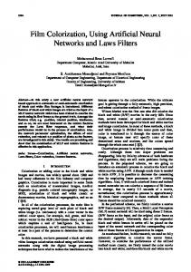
Movie scenes are changing gradually throughout the consequent frames, so the reference image is gradually loosing its credibility. Therefore we have to re-train our ANN using a new, manually-colorized, reference frame, after awhile. Colorization is basically an off-line process. The time advantage of the proposed method however, depends on the number of frames between two reference frames. E.g. having one reference per 4 seconds, means that we only need to manually colorize 1 = 1 = %1.04 of frames (24 4 × 24
A B/W film
© 2009 ACADEMY PUBLISHER
Colorizing the reference frame in the HLS color space.
Colorized reference frame
Configuring and training an ANN based on B/W reference frame.
METHODS AND TOOLS
A. The Proposed Method The proposed method relies on the merits of the neighborhood effect analysis of images as a high performance tool to extract the majority of gray level information, and a robust classifier to map the gray level pixel feature vectors to the corresponding color vectors. Amongst various neighbor-based schemes, the TFCM [9] is selected to extract the grayscale features. In a given scene, the color of a pixel generally can not be independent from its neighbors. This neighborhood effect simply can be interpreted as the texture of the region. Again, the edges determine the different segments of an image, segments that might have different colors. TFCM is promising in both texture and edge analysis. In fact the TFCM with optimized number of neighbor pixels or texture unit size, would be able to interpret the effects of neighborhood gray level variations, hence facilitates a concise texture/edge analysis. Moreover, a robust classifier/mapper would be of necessity to map from the grayscale space in to the color one. The classifier should be flexible against the noise and good in interpolation and generalization. The characteristics that hint us to employ the artificial neural networks. We firstly choose the first frame of the footage as the key or reference frame. This frame must be originally in color, or be colorized manually. The feature vectors of each pixel of the reference frame would be extracted next. A classifier is trained with grayscale/color pairs of the reference frame then. The trained classifier will be employed for the next frames automatic colorization. Fig. 1 illustrates a general flowchart of the proposed method.
96
frames/sec assumed). Cross-correlation between the current and the reference frame can be computed to signal the necessity of the reference renewal.
Trained ANN
Feeding the ANN by the B/W features of the next frames.
Colorized film in the HLS color space
Extracting texture features from B/W reference frame. Pixels’ feature vector of reference frame
Transferring colorized film to the RGB color space.
Colorized film in the RGB color space Figure 1. An overview of the proposed method.
B. Texture Feature Coding Method In this section, we propose an approach to generate texture feature numbers, called the texture feature coding method (TFCM). The design rationale of this method is based on a 3x3 texture unit as well as the gray-level variations of its eight surrounding pixels. TFCM is a coding scheme, which transforms an original image into a texture feature image whose pixels are represented by texture feature numbers. The texture feature number of each pixel X is generated on the basis of gray-level changes of its eight surrounding pixels, called a texture unit, a term described in Fig. 2. we consider the connectivity of the texture unit, the eight neighboring pixels in Fig. 2 constitute the eightconnectivity of the texture unit, which can be divided into the first-order four-connectivity pixels and second-order four-connectivity pixels. The four pixels labeled 1 satisfy the first-order four-connectivity of the texture unit because they are immediately adjacent to the pixel X. They are
JOURNAL OF MULTIMEDIA, VOL. 4, NO. 4, AUGUST 2009
denoted by first-order connectivity pixels. The other four pixels labeled 2 satisfy the second-order four-connectivity of the texture unit, which are diagonally adjacent to X and are denoted by second-order connectivity pixels. To code pixel X in Fig. 3, TFCM produces a pair of integers (α , β ) , where α and β represent gray-level variations of firstorder and second-order connectivity, respectively. As shown in Fig. 3, two scan lines along the 0 to 180-deg and 90 to 270-deg directions produce two sets of three successive first-order connectivity with pixel X in the middle of the horizontal and vertical lines formed by ©. Similarly, two scan lines along the diagonal directions 45 to 225 deg and 135 to 315 deg formed by ¯ also produce two sets of three successive second-order connectivity pixels as shown in Fig. 4. 2 1 2 1
X
1
2
1
2
Figure 2. The 3x3 texture unit of TFCM.
2
1
2
1
X
1
2
1
2
0-180 deg scan line 90-270 deg scan line Figure 3. First-order four-connectivity. ©:
2
1
2
1
X
1
2
1
2
45-225 deg scan line 135-315 deg scan line Figure 4. Second-order four-connectivity.
243
very close within the tolerance ∆ . Type 2 is the case where one pair of gray levels is within ∆ , but the gray-level variation of the other pair variation exceeds ∆ . Type 3 describes the case where the gray levels of a , b , and c are continuously decreasing or increasing with gray-level differences larger than ∆ . In Type 4, the gray-level variation is first decreasing then increasing, or first increasing then decreasing, where the increments and decrements exceed ∆ . 1 if ( Ga − Gb ≤ ∆) ∩ ( Gb − Gc ≤ ∆ ), 2 if [( G a − Gb ≤ ∆ ) ∩ ( Gb − Gc ≥ ∆)] ∪ [( Ga − Gb ≥ ∆) ∩ ( Gb − Gc ≤ ∆)], 3 if [(Ga − Gb f ∆) ∩ (Gb − Gc f ∆ )]
(1)
∪ [(Gb − G a f ∆ ) ∩ (Gc − Gb f ∆)], 4 if [(G a − Gb f ∆) ∩ (Gc − Gb f ∆)] ∪ [(Gb − G a f ∆ ) ∩ (Gb − Gc f ∆)].
According to this definition of gray-level graphical structure variation, the higher the type number is, the greater gray-level variation will occur. Since both α and β , corresponding to first and second order connectivity, respectively, have two scan lines, each of which can produce a type of gray-level variation, α and β can be assigned by a pair of gray-level graphical structure variations. The total number of combinations of arbitrary two gray-level graphical structure variations (including self combinations) is 4(4+1)/2=10. The ten combinations are listed in Fig. 6. The larger entry of Fig. 6 reflects more gray-level variation in the first-order or second-order connectivity.
¯:
Assuming that the scan direction is from the top down and left to right, the three successive pixels can be arranged as ( a, b, c) in the scanning order. For example, if ( a, b, c) represents pixels scanned by the vertical line of the firstorder connectivity in Fig. 3, the top pixel is denoted by a , pixel X by b , and the bottom pixel by c . Suppose that (Ga , Gb , Gc ) corresponds to the gray levels of three pixels ( a, b, c) , respectively. If we consider two successive graylevel changes between two pairs (Ga , Gb ) and (Gb , Gc ) , there are four different types of variations. The four types of gray-level variations, defined by (1), can be graphed by the gray-level graphical structure shown in Fig. 5. Type 1 describes the case that the gray levels of a , b , and c are
© 2009 ACADEMY PUBLISHER
Figure 5. Types of gray-level graphical structure variations. Scan line 1
Scan line 2
(i)
(ii)
(iii)
(iv)
(i)
1
2
3
5
(ii)
2
7
11
13
(iii)
3
11
17
19
(iv)
5
13
19
23
Figure 6. The variation generation of first-order (α ) or second-order ( β ) four-connectivity.
For example, if α or β =11, there is a combination of 2 and 3. More precisely, the columns represent the horizontal scan line 0 to 180 deg for α , or the diagonal line 45 to 225
244
JOURNAL OF MULTIMEDIA, VOL. 4, NO. 4, AUGUST 2009
deg for β . The rows represent the vertical scan line 90 to 270 deg for α , or the asymmetric diagonal line 135 to 315 deg for β . Finally, the texture feature number of each pixel is generated by taking the product of α and β . Let the gray-level of the pixel with spatial location ( x, y ) be denoted by G ( x, y ) , and the corresponding texture feature number by TFN ( x, y ) . Then TFN ( x, y ) = α ( x, y ) ¯ β ( x, y ),
(2)
Where α ( x, y ) and β ( x, y ) are values obtained using Fig. 6 for the pixel at spatial location ( x, y ) . In fact, TFN ( x, y ) can reflect the gradient of the spatial location ( x, y) . The TFN code does not change when the 3x3 texture unit locally rotates [10]. C. ANNs as the Classifier After studying different types of artificial neural networks and their applications, we concluded that a multilayer perceptron (MLP) neural network matches our requirements the best. The feedforward network is composed of a hierarchy of processing units, organized in a series of two or more mutually exclusive sets of neurons or layers. The first, or input, layer serves as a holding site for the inputs applied to the network. The last, or output, layer is the point at which the overall mapping of the network input is available. Between these two extremes lie zero or more layers of hidden units; it is in these internal layers that additional remapping or computing takes place. Links, or weights, connect each unit in one layer only to those in the next higher layer. There is an implied directionality in these connections, in that the output of a unit, scaled by the value of a connecting weight, is fed forward to provide a portion of the activation for the units in the next higher layer. Fig. 7 illustrates the typical feedforward network. The network as shown consists of a layer of d input units ( Li ) , a layer of c output units ( Lo ) , and a variable number (three in this example) of internal or “hidden” layers ( Lhi ) of units [11].
Since many studies suggest no benefit in increasing the number of hidden layers, we limit the ANN used to one hidden layer. A trial and error (T&E) scheme is employed however to optimize the number of hidden nodes within a rational range of a few tens. Using 30 hidden nodes is resulted from that trial and error procedure. We employ the scaled conjugate gradient (SCG) as the training scheme along with the linear squashing function. The number of training epochs is in the range of a few hundreds and optimized again by T&E. D. The HLS Color Space Watching a colored object, we can percept and describe its color using three parameters: hue (H), luminance (L), and saturation (S). Therefore, the HLS color space which is by a sense similar to the human color perception scheme, can be useful in colorization more than the typical RGB [12]. All the color footages are transferred to HLS before any further process. Fig. 8 illustrates the HLS color space. As the figure shows, angle which is made by horizontal axes (or axes of the red color), describes hue; e.g. the angles corresponding to red, green, and cyan colors are 0, 120, and 180 degree respectively. A vector directs from center of the circle to its perimeter, describes the level of saturation; i.e. the further from the center, the purer and more saturated is the color. While the vertical axis describes the level of luminance; i.e., the luminance would be directly proportional with the height.
Figure 8. The HLS color space. IV. IMPLEMENTATION AND TESTING
Figure 7. Layered feed forward network structure.
© 2009 ACADEMY PUBLISHER
As mentioned before, in this study we rely on the TFCM to extract the texture and edges information of a scene, and an ANN to map those information to the pixel hue and saturation (e.g. color information). Due to the mass of pixels within each frame, the ANN should deal with a rather complicated mapping problem, where the performance of the TFCM in extracting the most essential information is of essence too.
JOURNAL OF MULTIMEDIA, VOL. 4, NO. 4, AUGUST 2009
245
Procedure below shows the stages of the proposed approach in details: a) A reference frame is selected and colorized manually or automatically using [3]. In our tests however, we use a frame of the original color film. The color film is converted to the HLS color space too. b) The texture/edges information of the reference frame pixels are extracted using the TFCM applied on the luminance channel of the HLS space, we in fact consider the L subspace of the color frames as the B/W frames. c) An ANN is configured and trained, which uses the luminance and features of the B/W reference frame as the input, and generates the corresponding color vector (e.g. H and S) on its outputs. d) The trained ANN next will be fed by the B/W features of the next frames, and try to colorize them. e) The colorized frames are indeed in HLS space and might be converted to RGB.
µ = 0.012
(a)
µ = 0.011
A. The Colorization Errors To evaluate the performance of the proposed method, the sample set could be inspected by some human observers. Meanwhile, we employ the MSE error between the original color frames and the corresponding colorized frames as a mathematic evaluation criterion too. Equation (3) below shows the MSE between two frames: MSE =
1 2rc
2 2 ∑∑ ⎡⎢⎣(H ijO − H ijD ) + (SijO − SijD ) ⎤⎥⎦ r
c
(3)
(b)
i =1 j =1
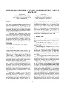
Where r × c is the frame size in pixel, H ijO and S ijO are the hue and saturation outputs of the neural network for pixel (i, j ) , and H ijD and S ijD are the desired or real hue and saturation of that pixel respectively. B. Experiments In all phases of implementation of this research inputs and outputs of desired ANN are normalized in [0,1] interval. Tests are done on a film with AVI format and resolution of 640x480 pixel (1.avi) whose size is reduced to ¼ (one fourth) of the real size means 160x120 pixel in order to fasten the colorization process and save the execution time of desired tests. Property of the film is slow changing in its consecutive frames. Also the film has 105 frames. The TFCM, based on gray level variations of a 3x3 and 5x5 (which is the generalization of the 3x3) texture unit were employed for gray level pixel feature extraction. Fig. 9 illustrates the MSE error plots for the film colorization using a 3x3 and 5x5 texture unit. The mean of each MSE error plot is calculated and shown in the corresponding diagrams. Fig. 10 illustrates comparison of the two previous MSE error plots in one diagram. Fig. 11 shows the colorized frames of the film.
© 2009 ACADEMY PUBLISHER
Figure 9. Colorization MSE error using TFCM, based on gray level variations of a 3x3 (a), and 5x5 (b) texture unit on 1.avi film.
µ 3×3 = 0.012 µ 5×5 = 0.011
Figure 10. Comparison of the two previous colorization MSE error l t
C. Results Justification As mentioned before, apart from the visual quality of the colorized footages, to verify the exact performance of the proposed method we can compare the results mathematically with randomly colorized footages. We firstly choose some frames of the B/W footage and colorize it randomly using [0-255] uniform random numbers. Again,
246
JOURNAL OF MULTIMEDIA, VOL. 4, NO. 4, AUGUST 2009
the same frames would be colorized by the proposed method. The MSE between each frame and the original color frame would be computed next. Table I below shows the result for the 2nd frame of the test movie, where the MSE resulted of the random colorization is 12 times more than the proposed method. This drastic decrease in the MSE justifies the proposed method. In order to extract texture feature, in section III, we generalize the TFCM using a 3x3 texture unit which is described in details in [10] to a 5x5 texture unit. In attention to the compared MSE error plot in Fig. 10, we conclude that generalizing the TFCM using a 3x3 to a 5x5 texture unit for texture feature extraction, decreases the MSE. The reason is that the generalized TFCM using a 5x5 texture unit around each pixel to code texture feature, in analogous to the original TFCM using a 3x3 texture unit around each pixel [10], attends to the texture correlation of that pixel not only with near neighbors, even with further ones; so texture feature of that pixel will be coded more precisely in attention to the near and far neighbors. TABLE I. MSE ERROR OF THE PROPOSED METHOD VS the RANDOM Method
Film 1.avi
Randomly colorized
The proposed method using 5x5 neighboring
0.14713
0.011826
V. CONCLUSION
In this paper, a new texture/color based method for B/W footages colorization was discussed. Regarding the advantages of the neighborhood effect analysis methods in edge and texture information extraction, the TFCM-based features of the B/W scenes were extracted and fed to a MLP neural network to map them to the most appropriate point at the HLS color space. The combination of the TFCM as the feature extractor and the MLP as the mapper performed well in B/W movies colorization. Both the visual quality of colorization and the MSE error were considered to verify our method. To extract texture feature, we generalized the original TFCM using a 3x3 texture unit around each pixel [10] to a 5x5 texture unit. This novation decreases the colorization MSE considerably. This study was aimed to evaluate the advantages and disadvantages of the high performance low level neighborbased visual features combined with a robust MLP classifier/mapper in a new domain which was automatic colorization and had been mostly carried out by high level methods formerly. The combination used is similar with the basic structure of the human visual system, therefore a promising performance was not unexpected. Trying other visual/texture features as well as different types of ANN would be advisable for further studies.
© 2009 ACADEMY PUBLISHER
REFERENCES [1] Levin, A., Lischinski, D., and Weiss, Y., 2004, “Colorization using Optimization”, ACM Transactions on Graphics, Vol. 23, No. 3, pp. 689-694. [2] Wikipedia Online Encyclopedia, August, 2007, “Film Colorization”, Available: http://en.wikipedia.org/wiki/Film_colorization. [3] Vieira, L. F. M., and do Nascimento, E. R., 2007, “Fully automatic coloring of grayscale images”, Image and vision computing 25, pp. 50-60. [4] Chen, T., Wang, Y., Schillings, V., and Meinel, C., January 27-30, 2004, “Grayscale Image Matting and Colorization”, Proceedings of ACCV2004, Jeju Island, Korea, pp. 1164-1169. [5] Irony, R., Cohen-Or, D., and Lischinski, D., 2005, “Colorization by Example”, Proceedings of Eurographics Symposium on Rendering 2005, pp. 201-210. [6] Li, Y., Lizhuang, M., and Di, W., 2007, “Fast Colorization Using Edge and Gradient Constrains”, Proceedings of WSCG'07, pp. 309-315. [7] Welsh , T., Ashikhmin, M., and Mueller, K., July 2002, “Transferring color to Grayscale Images”, ACM Transactions on Graphics, Vol. 21, No. 3, pp. 277-280. [8] Di Blasi, G., and Reforgiato Recupero D., September 2003, “Fast Colorization of Gray Images”, Proceedings of Eurographics Italian Chapter 2003, Milan, Italy. [9] Torrione, P., and Collins, L. M., July 2007, “Texture Features for Antitank Landmine Detection Using Ground Penetrating Radar”, IEEE Transactions on geoscience and remote sensing, Vol. 45, No. 7, pp. 2374-2382. [10] Horng, M. H., January 2003, “Texture feature coding method for texture classification”, Optical Engineering, Vol. 42, No. 1, pp. 228-238. [11] Schalkoff, R. J., 1997, Artificial Neural Networks, McGraw Hill. [12] Gonzalez, R. C., and Woods, R. E., 2007, Digital Image Processing, 3rd Edition, Prentice Hall. Mina Koleini, born 1984, in Isfahan, Iran. She got her BSc in Computer Engineering, software, from Department of Computer Eng., Faculty of Engineering, University of Isfahan in 2006. She is now an MSc Student in Computer, AI and Robotics at the same academy. Her focus of study is artificial intelligence, image processing, and neural networks. Seyed Amirhassan Monadjemi, born 1968, in Isfahan, Iran. He got his PhD in computer engineering, pattern recognition and image processing, from University of Bristol, Bristol, England, in 2004. He is now working as an assistant professor at the Department of Computer Engineering, Faculty of engineering, University of Isfahan, Isfahan, Iran. His research interests include pattern recognition, image processing, human/machine analogy, and physical detection and elimination of viruses. Payman Moallem, born 1970, in Tehran, Iran. He is an assistant professor in Electrical Engineering Department of University of Isfahan, Iran. He received his B.S. and M.S. both in Electronic Engineering from Isfahan University of Technology and Amirkabir University of Technology, Iran, in 1992 and 1995 respectively. He also received his PhD in Electrical Engineering from Amirkabir University of Technology in 2002. From 1994 to 2002, he has researched in Iranian Research Organization, Science and Technology (IROST) on the topics like, parallel algorithm and hardware used in image processing, DSP based systems and robot stereo vision. His interests include artificial intelligence, neural network, pattern recognition, image processing and analysis. He published more than 100 papers.
JOURNAL OF MULTIMEDIA, VOL. 4, NO. 4, AUGUST 2009
247
Scene, Frame 10- original
Frame 10- B/W
Frame 10- colorized
Frame 50- original
Frame 50- B/W
Frame 50- colorized
Frame 90- original
Frame 90- B/W
Frame 90- colorized
Peacock, Frame 10- original
Frame 10- B/W
Frame 10- colorized
Frame 50- original
Frame 50- B/W
Frame 50- colorized
Frame 90- original
Frame 90- B/W
Frame 90- colorized
Figure 11. Colorization using a 5x5 texture unit of TFCM.
© 2009 ACADEMY PUBLISHER