FINGERPRINT FEATUFCE EXTRACTION USING BLOCK-DIRECTION
ON RECONSTRUCTED IMAGES S. Kasaei, M. Deriche, and B. Boashash
Signal Processing Research Centre (SPRC), QU‘T GPO Box 2434, Brisbane Q 4001, Australia
[email protected] ABSTRACT Fingerprints have been used as unique identifiers of individuals for a very long time. As fingerprint databases are characterized by their large size and may contain noisy and distorted images, an efficient representation of the images is essential for a reliable identification. Considering fingerprints as sample images from non-stationary processes with flow patterns, we propose here a robust technique to extract their features. The unique properties of fingerprint textures are used to enhance the images and improve the fidelity of their features. The ridges are extracted from enhanced foreground areas based on local dominant ridge directions. The resulting bit-mapped images are thinned and smoothed to detect structural features. A large number of false features are eliminated in the proposed post-processing stage. The proposed algorithm results in an efficient and fast representation of fingerprints which accurately retains the fidelity in minutiae.
1. INTRODUCTION
In recent years, many efforts have been made in the research of personal verification methods using human biometric features. Fingerprint matching is the most popular and reliable biometric technique used in automatic personal identification. The main reason for popularity of fingerprint matching is that each fingerprint of a person is unique and its features remain invariant with age. The identification of fingerprint images is based on matching the features of a query fingerprint, against those stored in a database. Given that query fingerprint images are usually of poor quality and the fingerprint database is very large, an efficient representation of these images is essential. This r e p resentation should retain the discriminating power (to keep the uniqueness of fingerprints), be easily computable, amenable to automated matching al-
gorithms, stable and invariant to noise and distortions, and finally be efficient and compact [l].
There are two types of features to be extracted from fingerprints; high-level and low-level features. The high-level features characterize the “pattern class” while the low-level features characterize an individual fingerprint. The important high-level features are the core and delta points. The core point is the top most poiint on the inner most ridge and a delta point of the tri-radial point with three ridges radiating from it. These points are highly stable and also rotation amd scale invariant. Moreover, the distance between these singular points is used to reduce the search space in the database as well as to determine the ridge density. The fingerprint texture pattern can be corrupted by various kinds of noise causing breaks in ridges, bridges between ridges, and overall grayscale intensity variation. Despite this noise, humans can often analyze fingerprint images easily using such visual clues as local ridge orientation, ridge continuity, and small ridge curvature [2]. The goal of this work is to use these characteristics of fingerprint patterns to design a robust feature extraction algorithm. The proposed algorkthm, properly maintains natural shape of gray-level ridges as well as precise locations of minutiae, as opposed to the ridge extraction algorithm in [l]. Furthermore, it is fast and operates only on foreground regions, as o p posed to the adaptive floating average thresholding process discussed in [3]. 2. PROPOSED STRUCTURAL FEATURE EXTRACTION ALGORITHM
The increasing number oE fingerprints collected by law enforcement agencies has created an enormous problem in storage, transmission, and automated analysis. The authors have introduced an efficient compression technique for fingerprint images [4]. In this work, the reconstructed image from that algorithm is used as the input image. Given that most of low-energy high-frequency content is dis-
carded in the compression process, we can assume
1997 IEEE TENCON - Speech and Image Technologies for Computing and Telecommunications
’
303
Forcgr. I Backgr.
Reconstructed D
Fnhancement
E’Image
-L.
Segmentation
-
MinUtiaC
RidgeEntraction
that the noise in input images is already reduced considerably. Figure 1shows a schematic block diagram of the proposed algorithm. The input image is first enhanced and the foreground regions are segmented. The ridges are extracted from gray-level foreground regions and then thinned to have one pixel width. Finally, the minutiae are extracted and false minutiae are eliminated using the proposed rules based on their structural characteristics. These stages are explained in detail in the rest of this paper. 2.1. Enhancement of Fingerprint Images
The images are first standardized (that is, a zeromem unit-variance image) to have similar characteristics. To enhance the images, each 16 x 16 block is filtered using a library of filters based on the dominant ridge direction (DRD) given as [2]:
where G, and G, are the gradient magnitudes obtained using 3 x 3 Sobel masks. To get the correct 86 (0’ 5 8 b 5 B O 0 ) , the signs of the numerator and denominator are first checked. If the denominator is positive 90’ is added to o b , if the denominator is negative and the numerator is positive 180’ is added to otherwise is unchanged. The obtained DRDs are then quantized to one of the 16 possible directions in 0’ - 180’. The DRDs are used to form the block-direction image. The core and delta points can now be detected from block-direction image, since they have maximum direction variability in their neighborhood. Moreover, the DRDs with rapid changes are smoothed while the algorithm retains the rapid changes around the core and delta points, to keep their natural shape. To enhance the DRDs: 0
0
Form a matrix with each element representing DRD of a 16 x 16 blocks. Compute the standard deviation, g b , of each 3 x 3 block centered on each pixel. -
-
304
(e.g., 25), discard the center element c and compute a new &,. If o b > (Tt and l o b - (7bl < threshold (e.g., 0.9), the block is near a core or delta point then do not change c, otherwise;
If Ob 2
--D
Thining
--e
Exnaction
* * *
*
-
Post-Prcc&g
FP Features
*
Compute number of repeats. If there is no tie, replace c with the most repeated element, otherwise; Find the elements with minimum absolute distance from median of the block; {i : 3i I min(1i-medianl) i}. If there is no tie, replace c with i, otherwise; Find the element with minimum absolute distance from mean of the block ; {i : 3!i I min(li -mean]) . i}. Then replace c with i.
Figure 2, shows the obtained block-direction image before and after this smoothing process.
Figure 2: (a) Block-direction image (each line representing dominant ridge direction at each block); (b) Smoothed block-direction image. To enhance the image, each block is extended (by 3 in each side), to avoid artificial grid limes caused by convolution. The horizontally oriented filter (“3513” in [2]) is then rotated according to the DRD of the block and convolved with it. 2.2. Foreground/Background Segmentation
In fingerprint images, we can view a clear ridge area as the foreground and any other area (such as smudged and noise regions) as the background. The segmentation is based on the assumption that in a given block, noise regions have no dominant direction while clear regions flow in a particular direction [3]. Consequently, foreground regions exhibit a very high variance in a direction orthogonal to the orientation of the pattern and a very low variance along its DFtD. To segment the foreground region, we obtain the sum of variances in either of the mentioned
1997 IEEE TENCON - Speech and Image Technologies for Computing and Telecommunications
.
orientations. If the difference between these obtained values exceeds some threshold (e.g., 0.35), the region is assigned as foreground. We also noticed that after standardizing input images this difference gets larger leading into a more precise segmentation process. Using morphological operations, the obtained mask is then enhanced by ignoring the isolated and spur blocks.
spur pixels, using morphological operations associated with the spur anld clean masks. Figure 3 shows the extracted and the thinned ridges. The minutiae can now be extracted using the crossing number (CN) at a point P, expressed as [3]: a
C N = 0.5
- e,+,1,
p 9 =p1
(1)
i=l
2.3. Ridge Extraction Ridge extraction is the process by which the foreground area of a gray-level image is mapped into a black/white image. The noise caused by overinked/under-inked areas as well as skin elasticity can introduce major problems in this process. In fact this mapping is the major part of the preprocessing algorithm by which the correctness and efficiency of the extracted minutiae is determined. To extract the ridges: 0
0
where Pi are pixel values (zero or one) in a 3 x 3 neighborhood of P. The CNs of 1 and 3 correspond to an end pont (E;P) and Bifurcation point (BP),respectively. Computing the CNs, the minutiae within a margin of 32 pixels of image borders are extracted.
Extend each block to consider the energy of ridges near block endings. Rotate the block along the Y-axis (using its
DRD). 0
0
axis.
Figure 3: (a) Obtained black/white image; (b) Thinned and enhanced image.
Compute minima of this waveform to obtain center locations of dominant ridges.
2.5. Post-Processing
Compute the projected waveform on the X-
- Let one of the minima to be at the k-th column. - If the energy of pixels in k - 1, k, and IC 1 columns is less than the mean standard deviation of that block, assign these pixels as ridge points. - To further retain the natural shape of the ridges, if the energy of pixels in k 2 and IC 2 columns is less than the mean of that block, assign these pixels as ridge points, as well.
+
+
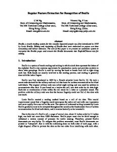
The preprocessing stage does not eliminate all possible defects in input images. In fact, the preprocessing stage itself might introduce some artifacts which may lead to spurious features. Figure 4 illustrates some of the basic false minutiae structures (after [5]).
+
0
Rotate the block to the original direction. Discard the extended area.
2.4. Minutiae Extraction
The resulting binary images need further processing before minutiae can be extracted. The extracted ridges must be first thinned to have one pixel width, while continuities of ridges are retained, In this work to thin the image, morphological operations are implemented using the thin and
skeleton masks on inverse images. The thinned image is then enhanced by removing isolated and
(e)
(0
(9)
(h)
Figure 4: Some basic false minutiae structures. The first step for eliminating false minutiae is to compute the ridge counting. Ridge counting determines how many friction ridges touch or cross an imaginary line drawn between the core and delta of a loop pattern. In order to obtain an accurate ridge count, it is important to know the exact core and delta locations. A number of rules exist in ridge counting [6]:
1997 IEEE TENCON - Speech and Image Technologies for Computing and Telecommunications
305
1. The count is made of the ridges between the core and delta, but the core and delta themselves are never included in the count.
2. If the imaginary line crosses exactly at the point of a bifurcation of ridges, two ridges are counted. 3. If the imaginary line passes through a ridge enclosure (either on the center or through the bifurcation end), a count of two ridges is
made at that point.
4. If the imaginary line touches a ridge island or dot, a count of one ridge is made.
5. A white space must intervene between the delta and the first ridge count. If no such interval exists, the first ridge must be disregarded. 6. The white space rule in counting loop ridges
does not apply in most instances in the core area of the pattern. Using the ridge counting, the average number of pixels between two adjacent thinned ridges, A, is obtained by dividing the ridge counting by the Euclidean distance between the core and delta points. To make the algorithm simple and fast, the thinned image is firstly divided into 16 blocks of equal sizes. Each block is then extended by 1.6X to cover minutiae of neighboring blocks. In the proposed false minutiae elimination process, we discard a minutia if:
1. BP and EP within a distance 1.5. 2. Two EPs within a distance 3.
3. BP and EP within a distance A. 4. Two BPs with the same orientation and within a distance 1.5X.
5. Two EPs within a distance A. 6. Two EPs within a distance 1.5X.
7. BPs and EPs within the extended area.
8. BPs and EPs within a specified border (e.g., 32) of boundary of foreground area. 9. EPs beside foreground mask areas. 10. EPs with two pixel distance from a continues line, detected by: 24
0.5xIPi-Pi+lI = 1,
p25 = pl. (2)
i=l
A large number of false minutiae are deleted using these rules. Figure 5 shows a portion of the extracted features before and after applying the proposed post-processing scheme. 306
(a)
(b)
Figure 5: Feature extraction stage: (a) Primitive features; (b) Final features [circles: end points, stars: bifurcation points]. 3. DISCUSSION
Using the unique properties of fingerprint textures and considering a wide area around image blocks and ridge centers, the proposed algorithm results in an efficient representation for fingerprint images. The images are properly enhanced and segmented using local dominant ridge directions. The ridge extraction algorithm, properly maintains natural shape of gray-level ridges as well as precise locations of minutiae. It is also fast as it operates only on segmented foreground blocks. The false minutiae are effectively filtered in the proposed post-processing stage using their structural characteristics and spatial relationships of minutiae. The proposed algorithm has been used on a variety of fingerprint images with very satisfactory results in feature extraction. 4. REFERENCES
[l] N. K. Ratha, S. Chen, and A. K. Jain. Adaptive Flow Orientation-Based Feature Extraction in Fingerprint Images. Pattern Recognition, 28(11):1657-1672, NOV.1995. [2] L. O'Gorman and J. V. Nickerson. An Approach to Fingerprint Filter Design. Pattern Recognition, 22(1):29-38, 1989. [3] B. M. Mehtre. Fingerprint Image Analysis for Automatic Identification. Machine Vision and App., 6~124-139,1993. [4] S. Kasaei, M. Deride, and B. Boashash. Fingerprint Compression Using Wavelet Packet Transform and P.vramid Lattice Vector Quantization. IEICE Special Section on Digital Signal Proc., ESO-A(8), August 1997. [SI Q. xiaoand H. mat. FingerprintImage postprocessing: A Combined Statistical and Structural Approach. Pattern Recognition, 24(10):985-992, 1991. [SI A. A. Moenssens. Fingerprint Techniques. Chilton Book Co.,Philadelphia, 1971.
1997 IEEE TENCON - Speech and Image Technologies for Computing and Telecommunications