ECCTD’01 - European Conference on Circuit Theory and Design, August 28-31, 2001, Espoo, Finland
Fingerprint Feature Extraction Using CNNs Qun Gao∗ and George S. Moschytz∗ Enrollee Finger
Abstract — Feature Extraction is an important step in fingerprint-based recognition systems. In this paper, a CNN Fingerprint Feature Extraction Algorithm is presented. It is applied to thinned fingerprints which have been previously obtained from real gray-scale, noisy fingerprints in the Image-Preprocessing stage, also by using CNNs. Examples are given to demonstrate the functionality of the proposed algorithm.
1 Introduction Cellular neural networks (CNNs) [1, 2] have demonstrated their usefulness in fingerprint-based personal identification for civilian applications, especially for portable applications [3–5]. We have previously successfully accomplished the Image-Preprocessing stage in fingerprint recognition by means of CNNs [3]. This has encouraged us to tackle the next stage: Feature Extraction. The successful results are described in this paper. 2 Fingerprint Recognition As shown in Fig. 1, a typical fingerprint-based recognition system [6, 7] operates in two distinct modes: enrollment and recognition. The purpose of the enrollment mode is to create a database. During this mode, an enrollee fingerprint is captured and processed in three stages: Fingerprint Reading, Image Preprocessing, and Feature Extraction. After the FeatureExtraction stage, a set of representative features of the enrollee fingerprint (the minutia template) is stored in the database. During the recognition mode, a fingerprint to be recognized undergoes the same three processing steps as in the enrollment mode. The result, a test minutia template, is compared with a minutia template from the database in the Feature-Matching stage. A match score which measures the degree of the similarity between the two minutia templates is calculated. Higher values indicate higher confidence in a match. In short, the main problem in fingerprint recognition is to decide how similar two fingerprints, i.e., their minutia templates, are. In this paper, we concentrate on the FeatureExtraction unit. 3 Fingerprint Feature Extraction The goal of the Feature-Extraction unit is to extract distinguishable features in fingerprints, as well as their attributes, in order to guarantee the next unit: Feature Matching. ∗ Signal
and Information Processing Laboratory, Swiss Federal Institute of Technology CH-8092 Zurich, Switzerland. Email:
[email protected], Tel: +41-1-6323503, Fax: +41-16321208.
Fingerprint Reading
Image Preprocessing
Feature Extraction
Database
Enrollment Recognition Claimed Finger
Fingerprint Reading
Image Preprocessing
Feature Extraction
Feature Matching
Decision
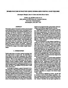
Figure 1: Block diagram of a typical fingerprint-based recognition system There are two main features in a fingerprint image: endings and bifurcations, as shown in Fig. 2. In a thinned fingerprint, an ending is the end point of a line, while a bifurcation is the junction point of three lines. For matching purposes, these so-called “minutiae” are usually denoted by their type, their location, and the direction of the adjacent ridge.
Bifurcation
Ending
Figure 2: Fingerprint features: endings and bifurcations Due to noisy original images and artifacts produced in the Image-Preprocessing stage, spurious minutiae will always be present. Therefore, after the minutiae are extracted, an important step, minutia reduction, is performed to eliminate the false minutiae in the FeatureExtraction stage. The spurious minutiae are normally eliminated by using empirically determined thresholds. In the following section, a CNN Feature-Extraction Algorithm which can accomplish these operations is presented. Throughout the paper, original, simple continuoustime CNNs [1] are employed. Keeping VLSI implementation of CNN chips in mind, the template neighborhood radius is restricted to 1 and all templates used are spatially invariant, linear, and as sparse as possible. The latter implies the use of several sparse templates rather than a smaller number of less sparse templates, because it has been shown [8] that this improves robustness with regard to the relatively large template tolerances that are inevitable with IC-implementation. 4 CNN Fingerprint Feature-Extraction Algorithm The proposed algorithm consists of 4 main processing units - Ending Detection, Bifurcation Detection, False Feature Elimination, and Direction Detection - in addition to several simple CNN operations, see Fig. 3. Each
I-97
of these 4 processing units accomplishes a specific task, and the second by as its name implies, and will be explained separately in 0 0 0 0 1 0 , A= detail in the subsequent subsections. 0
Ending Detection
Logic AND
Logic OR
Bifurcation Detection
False Feature Elimination
Direction Detection
False Feature Elimination
Direction Detection
0
0
B=
γ γ γ
γ 2γ γ
γ γ , γ
I = 7γ ,
(2)
where γ is a scaling factor. Higher γ accelerates the convergence. An example is shown in Fig. 4.
False Feature Elimination
Logic AND
Figure 3: Block diagram of Fingerprint Feature Extraca) b) c) tion Figure 4: Example of Ending Detection: a) input, b) afFirst, the endings and bifurcations will be extracted in ter Isolated Point Elimination, c) output (Ending image) parallel from the thinned input fingerprint image in the Isolated Point Ending & Isolated Ending-Detection and Bifurcation-Detection units. As Elimination Point Detection a result, an ending image and a bifurcation image are obtained. These two images are added together in the Figure 5: Block diagram of the Fingerprint EndingLogic OR operation [9], and the output fed to the False Detection Algorithm Feature-Elimination unit. Here, false feature pairs, i.e., ending and bifurcation pairs resulting from so-called 4.2 Bifurcation-Detection Algorithm spurs [7] can be deleted, based on an empirically de- Bifurcations are the junction points of three lines in a thinned fingerprint image. Thus, a bifurcation has only termined threshold, see Section 4.3. With the subsequent Logic AND [9] we obtain 3 black neighbours in its nearest 3 × 3 neighbourhood. a new ending/bifurcation image in which false end- But not all points which have only 3 black neighbours ing/bifurcation pairs resulting from spurs have disap- are bifurcations, see Fig. 6 a). This is taken into account peared. In the following two False Feature-Elimination by our algorithm (see Fig. 7). operations, false endings and false bifurcations are eliminated separately. The corresponding thresholds are presently determined empirically, see Section 4.3. The remaining endings and bifurcations are regarded as real a) b) c) d) e) features and result in an ending feature image and a biFigure 6: Example of Bifurcation Detection: a) input, furcation feature image. Finally, the direction of ridges leaving endings and b) after Junction Point Extraction, c) after Isolated Point bifurcations is extracted separately in the Direction- Detection, d) after Junction Point Extraction in T- and Corner-form, e) output Detection units. Thus, with our Fingerprint Feature-Extraction AlgoIsolated Point rithm, we obtain four feature images from a thinned Extraction fingerprint input: ending image, ending direction imJunction Point Logic Extraction OR age, bifurcation image and bifurcation direction image. [Note that, unlike with digital methods, we do not Junction Point Extraction in T- and Corner-form have the location of the features.] These four feature images are then used as a basis for comparison in the Figure 7: Block diagram of the Fingerprint Bifurcationnext stage, Feature Matching. In what follows, these Detection Algorithm four steps are briefly described separately. Referring to Fig. 7, in “Junction Point Extraction”, 4.1 Ending-Detection Algorithm the black pixels which have at least 3 black neighbours Ridge endings are the termination points of lines in a in their nearest neighbourhood are extracted. The thinned fingerprint image. This implies that an ending corresponding template set is given by point has only one black neighbour in its nearest 3 × 3 γ γ γ 0 0 0 neighbourhood, see Fig. 4 a). Thus, we can find these A = 0 1 0 , B = γ 6γ γ , I = 3γ . (3) γ γ γ 0 0 0 points by first eliminating all isolated black points, and then finding all black points that have at most one However, this will still leave T- and Corner-forms (see black neighbour, see Fig. 5. The template for the first Fig. 6b) from which we have to extract real bifurcations. operation by For this, the resulting image goes through two different is given γ γ γ 0 0 0 operations in parallel: Isolated Point Extraction [9] A = 0 1 0 , B = γ 8γ γ , I = γ , (1) and Junction Point Extraction in T- and Corner-form. γ γ γ 0 0 0
I-98
The first extracts black pixels which are alone in an input image, the second retains only black pixels which have at least 2 black neighbours among their north, east, south, and west neighbours. The corresponding template set is given by
0 A= 0 0
0 1 0
0 0 0 , B= γ 0 0
γ 4γ γ
0 γ , I = 0
only the black pixels whose northeast and southwest neighbours are both black remain black. A similar principle holds for Erosion /. The corresponding template sets are given by (6) and (7).
0 A= 0 0 0 A= 0 0 0 A= 0 0
3γ . (4)
The results of these operations can be seen in Fig. 6 c) and d). Finally, we add the resulting images to obtain only the bifurcations, see Fig. 6 e). 4.3 False Feature-Elimination Algorithm For the reasons mentioned in Section 3, false minutiae - endings and bifurcations - are not always avoidable after Ending Detection and Bifurcation Detection. It is necessary to eliminate them in order to facilitate the comparison of two fingerprints in the Feature-Matching stage. Experience shows that two false minutiae - two false endings, or two false bifurcations, or one false ending and one false bifurcation - are normally close to each other [7]. As a consequence, we have developed a CNN False Feature-Elimination algorithm that can eliminate two black points with a distance smaller than or equal to n pixels. Here distance means the number of white pixels separating two black pixels. Presently, we have determined n empirically for different cases. To delete two false endings, n (referred to as n e ) should be smaller than the minimum of the distance between two real endings. The same holds for two false bifurcations (n b ), and for a pair consisting of one false ending and one false bifurcation (n s ). In addition, we require that n s < min (n e , n b ). Ultimately, all thresholds will need to be fixed for a general-purpose CNN-based fingerprint recognition system, unless an adaptive learning process can be found to find the optimum thresholds. Erosion /
n/2
Dilation
Logic OR
n/2
Isolated Point Extraction
0 1 0 0 1 0 0 1 0
0 γ 0 , B= γ 0 γ 0 0 0 , B = 0 γ 0 γ 0 0 , B = 0 0 0
γ γ γ 0 γ 0 0 γ 0
γ γ , I = 8γ . (5) γ γ 0 , I = 2γ . (6) 0 0 0 , I = 2γ . (7) γ
After this, the two resulting images will be added together in the Logic OR operation, and finally the Isolated Point Extraction operation is applied. The key point using these two Erosion operations instead of a conventional Erosion operation for all directions is to guarantee that after n/2 Dilation operations, and n/2 Erosion operations, two points separated by n pixels on a diagonal remain connected, so that they can be eliminated in the following operations. An example is shown in Fig. 9 with n = 2. As can be seen, three pairs of points, whose distance is equal to two, were deleted. Finally, only two points, whose distance to any other point is larger than two, remained.
a)
b)
e)
c)
f)
d)
g)
Figure 9: Example of False Feature Elimination: a) input, b) after one Dilation, c) after one conventional Erosion in all directions, d) after one Erosion /, e) after one Erosion /, f) after Logic OR, g) output To find the template sets (1) (7), we applied the exact, analytical design approach in [10].
Erosion \
n/2
Figure 8: Block diagram of the False Feature-Elimination Algorithm (for distance ≤ n-pixels, n is even)
4.4 Direction-Detection Algorithm
In digital fingerprint-based recognition systems, the direction of ridges leaving endings and bifurcations is repOur algorithm is shown in Fig. 8. Assuming that resented by a vector parallel to the ridges leaving minun is given, the input first goes through the Dilation tiae. In a planar CNN system, this cannot be done, beoperation n/2 times. Its template set is given by (5). cause the output of the system is an image. In order to extract the direction of ridges leaving endThe Dilation operation makes each black pixel dilate by one pixel in all directions. After n/2 Dilation ings and bifurcations, we use the CNN operation Figure operations, two points whose distance is equal to or Reconstruction [9]. With this operation, we can reconsmaller than n pixels will be connected together and struct one or several figures from an input image by usform an ensemble. This ensemble will then go through ing a suitable initial state. If we wish to reconstruct only two different Erosion operations in parallel, Erosion / part of a figure, we must stop this CNN operation afand Erosion /, n/2 times. Erosion / works as follows: ter an appropriate number, τ , of CNN integration steps.
I-99
With a suitable τ , this CNN operation can restore a short section of the ridge leaving an ending, and a short section of each of the three ridges leaving a bifurcation. Fig. 10 shows the result of the Figure-Reconstruction operation applied to the first images in Fig. 4 and Fig. 6 by using these two images as the input of the operation, and the last images in Fig. 4 and Fig. 6 as the initial state of the operation, respectively. In this example, we chose τ equal to 12. These short sections of the ridges leaving feature points can be regarded as the so-called direction information that we need.
recognition. It is able to extract almost all genuine endings and bifurcations and their corresponding direction attributes, and to eliminate the spurious endings and bifurcations which may result from the noisy original fingerprint, and the previous processing operations. Together with our Fingerprint Image-Preprocessing algorithm [3], the proposed algorithm will facilitate the next important stage in fingerprint recognition, i.e., the Feature-Matching stage. This latter stage is presently being completed and will be reported on shortly. References [1] Leon O. Chua and Lin Yang, “Cellular Neural Networks: Theory,” IEEE Transactions on Circuits and Systems–I, vol. 35, no. 10, pp. 1257–1272, Oct. 1988.
a)
b)
Figure 10: Example of Direction Detection: a) Ending Directions, b) Bifurcation Directions 4.5 Examples In order to demonstrate the performance of the proposed CNN Fingerprint Feature-Extraction Algorithm, we applied it to a thinned fingerprint input which has been obtained by applying our Fingerprint Image-Preprocessing algorithm [3] onto a gray-scale fingerprint image of size 256 × 256, as shown in Fig. 11 a) and b). Figs. 11 c) - f) illustrate the “ending” image and the “ending direction” image, the “bifurcation” image and the “bifurcation direction” image, corresponding to the region within the dashed line in the thinned fingerprint, respectively. The parameters used in these examples are n s = 2, n e = n b = 6, and τ = 22. The four feature images obtained will be saved in the database in the enrollment mode, while in the recognition mode they will be used for comparison purposes in the Feature-Matching stage.
[2] Leon O. Chua and Lin Yang, “Cellular Neural Networks: Applications,” IEEE Transactions on Circuits and Systems–I, vol. 35, no. 10, pp. 1273–1290, Oct. 1988. [3] Qun Gao, Philipp Förster, Karl R. Möbus, and George S. Moschytz, “Fingerprint Recognition Using CNNs: Fingerprint Preprocessing,” in Proceedings of the IEEE International Symposium On Circuits and Systems, Sydney, Australia, May 2001, vol. 3, pp. 433–436. [4] Kenneth R. Crounse and Leon O. Chua, “Methods for Image Processing and Pattern Formation in Cellular Neural Networks: A Tutorial,” IEEE Transactions on Circuits and Systems–I, vol. 42, no. 10, pp. 583–601, Oct. 1995. [5] Tibor Kozek et al., “Simulating Nonlinear Waves and Partial Differential Equations via CNN–Part II: Typical Examples,” IEEE Transactions on Circuits and Systems–I, vol. 42, no. 10, pp. 816–820, Oct. 1995. [6] A. Jain, R. Bolle, and S. Pankanti, Biometrics: Personal Identification in Networked Society, Kluwer Academic Publishers, 1999. [7] L. C. Jain et al., Intelligent Biometric Techniques in Fingerprint and Face Recognition, CRC Press, 1999.
a)
d)
b)
e)
[8] Bahram Mirzai, Robustness and Applications of Cellular Neural Networks, Ph.D. thesis, Diss. ETH Zurich Nr. 12483, Swiss Federal Institute of Technology, ETHCenter, CH–8092 Zurich, Switzerland, 1998, ISBN 389649-307-8.
c)
f)
Figure 11: Examples: a) gray-scale fingerprint, b) thinned fingerprint, c) “ending” image, d) “ending direction” image, e) “bifurcation” image, f) “bifurcation direction” image 5
Conclusions
[9] Tamás Roska et al., “CNN Software Library (templates and algorithms), vers. 7.3,” Tech. Rep. DNS-CADET15, Analogical & Neural Computing Laboratory, Computer and Automation Research Institute, Hungarian Academy of Sciences, 1999. [10] Martin Hänggi and George S. Moschytz, “Making CNN Templates Optimally Robust,” in Proceedings of the International Symposium on Nonlinear Theory and its Applications, Crans-Montana, Switzerland, Sept. 1998, vol. 3, pp. 935–938.
We have presented a CNN algorithm which accomplishes the Feature-Extraction stage in fingerprint
I-100