08SFA-101
Finite Volume (FV) and Finite Element (FE) integration in Simufact.forming A.J. Buijk Simufact-Americas LLC (
[email protected]) Keywords: Finite Volume, Finite Element, Simufact.forming, Metal Forming, Forging, Extrusion, Upsetting, Rolling, Bending, Cross-Wedge-Rolling, Reducing, Trimming Copyright © 2008 Simufact-Americas LLC
ABSTRACT No single technology is able to simulate the full spectra of manufacturing processes available. By integration into one product (Simufact.forming), two complementary solution methods, namely the Finite Volume and the Finite Element methods, it has become possible to solve virtually every manufacturing process imaginable, from beginning to end. This paper will demonstrate where each technology applies individually, and how it is seamlessly applied to a sequence of forging operations.
INTRODUCTION The need, motivation and value of numerical simulation of metal forming processes are clearly described in [1] & [2]. The bottom line is that for survival in today‟s competitive global environment, companies have to include simulation into their design process. This paper will focus on the enabling technologies that are available in the software program Simufact.forming. This is a commercial software package dedicated to the simulation of manufacturing processes. The strength of simufact.forming is that the program inputs are all based on shop floor terminology, while the geometries are defined by means of regular 3D or 2D CAD. The conversion of the physical problem descriptions into a mathematical model is done fully automatic. From a user‟s perspective, there is no difference between running a simulation with the Finite Element Method, the Finite Volume method, in 2D, or in 3D. Two case studies will be presented, with a description of the numerical methods used.
FORMULATION OF THE PHYSICAL PROBLEM The forming processes under discussion involve the change in shape of a solid piece of metal, under loadings applied to it by multiple tools & dies. The forming process can be done at either room, warm or hot temperature,
and at either slow or fast speed. The initial shape can be any shape, like:
Bar Sheet Disk Ring Any other shape…
The forming process can involve one step or multiple steps with different tools being used in each step. The material being formed can be any metal, like:
Aluminum Brass Copper Lead Magnesium Steel Titanium Uranium Zircalloy Zirconium ….
The forming process is a sequence of any imaginable operation, like: Upsetting Bending Cross-Wedge Rolling Reducing Cogging Closed Die Forging Open Die Forging Stamping Extrusion Heading Coining Spinning Trimming Machining …
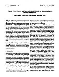
MATHEMATICAL FORMULATION All the forming operations under discussion are simulated using a combination of the Finite Element and Finite Volume methods. The state of the material being formed is captured at all times during the forming process, as well as the required forces & energy that need to be applied, plus the deformations and stresses of the tools. The material state that is captured includes the temperature, stress, strain, strain-rate, and microstructure information like grain-size. In all these forming processes, the space occupied by the material and the tools is „meshed‟ into „elements‟, and the resulting mathematical representation is then solved using either the Finite Element or the Finite Volume method. The key difference between the Finite Element method and the Finite Volume method is the way in which the material deformation is calculated, as shown in Figure 1.
The accuracy of the Finite Element method is determined by the element type used. Several element types are available, identified by its shape, and the number of integration points. The most accurate element type is the hex element with 8 nodes, and 8 integration point. All Finite Element examples shown in this paper are simulated using this element type. In the next sections, we will present two case studies and describe the solution method that was used for each operation.
HOT FORGING OF DRAWING LUG A drawing lug is formed during a hot-forging process consisting of 3 operations, with following simulation methods. Operation
Method
Upset 1
3D Finite Element – Hex
Upset 2
3D Finite Element - Hex
Closed Die
3D Finite Volume
All operations are performed on a Hydraulic press, with a constant velocity of 250 mm/sec. The billet material is DIN 1.0570, with a uniform initial temperature of 1250 °C.
Figure 1: Material deformation in FE & FV methods In the Finite Element method, the material is „connected‟ to an FE-element, and as it deforms, the FE-element deforms with it. In the Finite Volume method, the material is not „connected‟ to an FV-element. When the material deforms, it “flows” from one FV-element into another, while the FV-elements themselves do not deform. The outer surface of the material is captured by means of triangular facets. In principle, both solution methods can be applied to any of the forming operations under consideration, but the different treatment of the material deformation has an impact on the applicability. The fact that the FV-elements do not deform with the material, makes the Finite Volume method extremely efficient and accurate when applied to 3D hot forging processes, involving complex material flow. All other forming processes, as well as die stress simulations are most efficiently and accurately solved with the Finite Element solver.
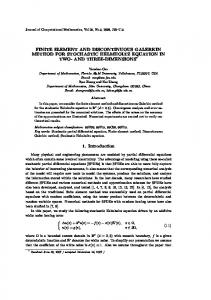
Die Contact during final stage. Figure 2: Work-piece shape. Note that a large fold is formed during the final stage.
Die Contact during final stage.
Figure 4: Work-piece shape at end of each operation.
Figure 3: Work-piece shape with reduced stroke during nd rd 2 Upset. Note that no fold is formed during the 3 stage.
CONCLUSION It was confirmed by shop-floor try-outs that it is indeed nd required to use a reduced stroke during the 2 upset to prevent the fold.
HOT FORGING OF STEEL CONNECTING ROD A steel connecting rod is formed during a hot-forging process consisting of 8 operations, with following simulation methods. Operation
Method
Cross Rolling: 4 passes Upsetting
3D Finite Element - Hex
Pre Stage
3D Finite Volume
Final Stage
3D Finite Volume
Trimming
3D Finite Volume
3D Finite Element - Hex
It is now possible to simulate virtually every metal forming process imaginable, by a seamless combination of the Finite Element and the Finite Volume method. Examples for two case studies were given, and it was shown where the Finite Element method is best applied and where the Finite Volume method is best applied. This powerful technology is now available in the commercial simulation program Simufact.forming, and can be applied by design departments of any size company.
ACKNOWLEDGMENTS The author would like to thank Andreas Hagen for preparation of the example models.
REFERENCES st
The Upsetting, Pre-Stage and Final-Stage operations are performed on a crank press, with properties: Crank Radius = 300 mm Rod Length = 1000 mm Revolution = 30 rotation/min
1. C. Jackson, The 21 century mold and die shop, benchmark research report, Aberdeen Group, March 2007 2. M. Wohlmuth, H. Schafstall, Forging simulation – a question of competition in a global manufacturing market, ICTP, paper 1493, Korea, September, 2008
CONTACT The billet material is DIN 1.7131, with a uniform initial temperature of 1280 °C.
The author can be contacted by e-mail at:
[email protected]