11th IEEE Symposium on Object Oriented Real-Time Distributed Computing (ISORC)
First experiments using the UML profile for MARTE Sébastien Demathieu (1), Frédéric Thomas (2), Charles André (3) , Sébastien Gérard (2), François Terrier (2) (1) Thales Research & Technology, RD 128, 91767 Palaiseau Cedex
[email protected] (2) CEA LIST – Boîte 94 – Gif sur Yvette 91191 – France {frederic.thomas, sebastien.gerard, francois.terrier} @ cea.fr (3) I3S, Université de Nice Sophia Antipolis, CNRS/INRIA
[email protected] The Object Management Group (OMG) promotes, among other technologies, a general-purpose modeling language named the Unified Modeling Language [1]. Its latest release, UML 2, is getting a large audience in the software engineering community. Nowadays, UML is also emerging as a possible solution for providing benefits to embedded systems developers. While UML can be used with all major object and component based modeling methods, it appears that the language lacks quantifiable notions of time, as well as the ability to express non-functional properties and execution platforms. All these aspects are particular concerns to real-time and embedded system designers and developers. The issue of how to add such capabilities to UML has been addressed in different research and industrial contexts, mostly by the definition of specific dedicated UML profiles, such as [2][3][4][5]. A profile is a powerful extension mechanism for UML; however, most of these extensions, which cover a wide range of applications, are proprietary and suffer a lack of standardization. This misalignment onto the idea of a standard language is very problematic since it discourages and limits their industrial exploitation. Standardization ensures definition of a common framework for both notation and semantics related concerns, while allowing dissemination of the best modeling practices. Standards are also a cost effective solution, since they foster tool interoperability and lower overall training costs. Additionally, this helps to manage the risks on tool evolution and maintenance, reducing the dependency on one single tool. In that context, the Object Management Group (OMG) has encouraged proposals for standard UML extensions dealing with real-time concerns such as timing properties, as well as non-functional and platforms aspects.
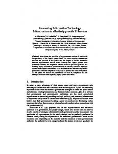
Abstract A UML profile for Modeling and Analysis of RealTime and Embedded systems (MARTE) has been recently standardized by the OMG. This initiative meets the needs of several Thales divisions (e.g., aerospace, land and joint and air systems), which develop real-time and embedded systems. CEA LIST, INRIA and Thales have been the main contributors to the MARTE standard through the ProMARTE consortium. To foster the deployment of MARTE in Thales divisions, we have launched the development of a case study related to a real-time and embedded system using the MARTE adopted specification. As a first step of this study, we make use of a fictive system—the Josefil challenge—to evaluate whether the profile is applicable to the Thales current systems and software engineering practices. The purpose of this paper is to report on this first stage and outline the next scheduled activities.
1.Introduction Thales is already using Model-Driven Engineering (MDE) to support its systems and software engineering processes. This approach has proven its benefits in term of cost reduction and quality improvement. MDErelated techniques are currently deployed in several Thales divisions to support developments of largescale distributed and safety-critical systems. As RealTime and Embedded Systems (RTES) have a significant position in Thales business, there is a strong interest in deploying model-based techniques in this segment as well. However, only a few attempts have been made so far. The main reason is the lack of a modeling language that can capture the essential concepts of the real-time and embedded domain.
978-0-7695-3132-8/08 $25.00 © 2008 IEEE DOI 10.1109/ISORC.2008.36
50
Authorized licensed use limited to: Baylor University. Downloaded on December 23, 2008 at 15:23 from IEEE Xplore. Restrictions apply.
conclusions on this experiment and drafts remaining ongoing work related to MARTE.
SysML [6] has been recently adopted by the OMG as a language to model complex systems, including software, hardware, facilities, and process aspects. Although SysML native capabilities to model RTES are far better than UML ones, some required features such as strict timing modeling and real-time resource management are poorly supported by SysML or are completely missing. Another OMG specification, targeting the real-time and embedded domain, is the UML profile for Schedulability, Performance and Time (SPT) specification [7]. It provides a straightforward annotation mechanism with a limited set of common annotations to perform either schedulability analysis (e.g., rate monotonic analysis), or performance analysis (e.g., queuing theory based analyses). Past experiences of the SPT profile have led to a number of significant suggestions for its improvement and consolidation. Both synthesis documents [8] and [9] gather all raised issues. This includes new requirements for specifying both software and hardware aspects, alignment on UML 2, compliance with the Model Driven Architecture (MDA) [10] for defining separately the platform the application and allocation models, or also modeling of additional non-functional aspects such as power consumption or memory size. Part of these issues was deemed too disruptive for a simple revision of the current SPT profile of the OMG. Hence, the OMG requested for a proposal of a new UML profile for the Modeling and Analysis of Real-Time and Embedded systems (MARTE) [11]. The submission work to the MARTE request for proposal has been carried out by the ProMARTE consortium. CEA-LIST, INRIA and Thales have been the main contributors to this OMG consortium which has federated tool vendors (e.g., ARTiSAN, IBM, No Magic, Telelogic), industrials (e.g., Alcatel, France Telecom, Lockheed Martin) and academic partners (e.g., Carleton University, CMU SEI) interested in the definition of a modeling standard to support the realtime and embedded domain. In that context, we have started a robotics case study related to the development of real-time software systems using MARTE. We have used the Papyrus UML tool [12], which implements the OMG adopted specification, to create MARTE models of the robotics system. The goal is to evaluate whether the profile is applicable to our current systems and software engineering practices. The paper is then structured as follows: Section 2 presents an overview of the MARTE profile; Section 3 discusses the experiment on a robotics case study Josefil [12]; this section illustrates how key features of the MARTE profile have been used to specify realtime behavior and to model hardware and software execution platforms; finally, this paper draws some
2.The MARTE UML Profile The MARTE specification consists of three main packages. The first package defines the foundational concepts used in the real-time and embedded domain. It provides basic model constructs for non-functional properties, time and time-related concepts, allocation mechanisms and generic resources, including concurrent resources. These foundational concepts are then refined in two other packages to respectively support modeling and analysis concerns of real-time embedded systems. The second package addresses model-based design. It provides high-level model constructs to depict realtime embedded features of applications, but also for enabling the description of detailed software and hardware execution platforms. The third package addresses model-based analysis. It provides a generic basis for quantitative analysis sub-domains. This basis has been refined for both schedulability and performance analysis.
Figure 1. Overview of the UML MARTE Profile
3.Experimenting MARTE on a case study The MARTE specification is a language extension to UML, hence it does not provide any methodologyrelated hints for developing RTES. The next sections do not then refer to a specific methodology, but are intended to illustrate the UML profile for MARTE capabilities. This experiment report copes with: time constraint modeling in a logical system decomposition, hardware resources modeling and software resources modeling. We demonstrate those key features of the UML profile for MARTE considering the Josefil case as the system to design. Using a selected subset of diagrams, we illustrate how MARTE helped capturing those essentials concepts of the real-time and embedded domain.
51
Authorized licensed use limited to: Baylor University. Downloaded on December 23, 2008 at 15:23 from IEEE Xplore. Restrictions apply.
All the packages introduced in the MARTE specification have not been used in the context of this case study. We focused on the design of the system during this first stage. As a consequence, we have not used the GQAM, SAM or PAM packages for analysis purposes (either scheduling, performance or other kind of quantitative analysis). In the design of our system, we realized that dealing with specific component models introduced in the real-time and embedded domain was not a key concern and we did not need to use the extensions that are provided by the GCM package. Additionally, we preferred to use the modeling constructs of HRM and SRM for resource modeling rather than the more abstract GRM package. Finally, we did not use the RTEMoCC package. The later provides interesting some features to model a real-time application at a high level of abstraction but it brings in a novel approach to RTES design that we would like to study separately before introducing it in our case study.
3.2.Logical system decomposition In this section, we present a first logical decomposition of the case study, and demonstrate how MARTE can be used to support system-level design. We focus here on the specification of the robot, leaving apart the control station. Taking into account the key requirements of the case study, we identify the system use cases then model use-case realizations as a series of sequence diagrams and activity diagrams. Based on these use case realizations, we identify consistent group of functions, represented as UML classes in Figure 2. We define attributes, operations and associations for these classes, thus providing a first definition of internal interfaces of the system. As depicted in the Figure 2, the robot architecture consists of five logical entities respectively dedicated to: the management of communications with the control station (CommunicationLink), the LED control (DisplayController), the control of the engine (EngineController), the computation of trajectories (TrajectoryController) and the system supervision (Supervisor). The last logical entity manages the global state and behavior of the system. This structural model is used in the rest of this paper to illustrate the key features of MARTE.
3.1.The Josefil case study The Josefil case study consists in developing a robotics system following model-driven engineering practices. This application has been defined in the context of an academic challenge [12], the goal of which was to provide a case study framework for benchmarking different kinds of design approaches to distributed real-time and embedded systems. We chose this case study because it is fairly representative of many problems encountered by systems and software engineers when designing such systems. The case study introduces a control system for an exploration robot that carries out temperature measurements in a hostile environment. It consists of a robot—equipped with sensors—which communicates with a remote control station through an Ethernet wireless link. During a mission, the robot has to follow a route transmitted by the control station. The environment is made up of stationary objects that shall be avoided by the robot. The robot is also equipped with an engine and driving wheels. A microcontroller controls the speed and calculates the absolute position of the robot. It also manages the different sensors and activators. Additionally, an embedded PC supervises the robot behavior and provides connection to the microcontroller. In order to follow the execution of a mission in real-time, the robot has a movie camera, which returns frames displayed on a remote control station used by a human operator. Finally, the control station provides the ability to transmit various instructions (e.g., to set the current speed or to indicate alternative routes), which may be required for the progression of the mission.
Figure 2. Logical decomposition of the robot subsystem At this stage of the development, it is usual to identify end-to-end performance scenarios. They are often directly extracted from customer requirements and may be used later on to assess the response times of the system. In this context, engineers may need to specify either the duration of a single processing or the duration related to the execution of an end-to-end flow. Description of such information within the model may be achieved by annotating UML 2 interaction diagrams. UML 2 defines constructs to express time-related notions in a package called CommonBehaviors:: Communications::SimpleTime. These concepts provide a good basis to support the representation of time events, instants and durations in UML 2. However, it misses a more formal definition of the concept of time. Depending on the system to model (whether it is distributed or not), the design approach
52
Authorized licensed use limited to: Baylor University. Downloaded on December 23, 2008 at 15:23 from IEEE Xplore. Restrictions apply.
control message. We apply again the previous stereotype to refer the same ideal clock. Our purpose is then now to express that the time elapsed from the instant when the control station sends the command until the engine actually process the order shall not take more than one second. For that purpose, we define a time constraint, the body of which is defined in the VSL language. In a VSL expression, we indicate that the duration between the two previously defined observations: receiveControl and sendCommand shall not exceed 1000 ms. The time dimension (NFP_Duration) along with a collection of time units is defined in the MARTE model library. The constraint body can be parsed and typed as an inequality between two durations. Note that, the notation defined in the UML SimpleTime lacks a concrete support in terms of tooling. This notation, quite natural when sketching diagrams on a whiteboard, is not implemented in any commercial tool on the market. Fortunately, it is supported in the Papyrus [12] open source implementation of MARTE. This has been one of the key factors for choosing Papyrus in our case study.
and the abstraction level, one may deal with physical time or logical time (discrete or continuous). Moreover, the system may rely on one or several clocks. All this information has a strong impact on the diagram semantics and needs to be explicitly stated. Another important point is the lack of constructs to express complex time constraints in the UML2 SimpleTime package. To overcome these issues, MARTE extends the UML 2 SimpleTime package introducing stereotypes that refine UML time events, time observations and duration observations with explicit references to clocks. In addition, let us note that a system may have one or several clocks and it is then also possible to define clock constraints in order to either impose dependencies or define relationships between the clocks. A MARTE model library provides predefined time units and clocks, such as idealClk. This ideal clock is supposed to faithfully respect physical time (i.e., with no skew or drift). MARTE also provides a general-purpose mechanism to express non-functional properties (NFP) in UML models, and to specify constraints on these properties. This mechanism relies on the possibility to annotate UML diagrams with constraints stereotyped as « nfpConstraint » and « timedConstraint ». We will see later in this paper that this mechanism is applicable to various non-functional properties (e.g., memory size, network throughput or power consumption). We focus here on how to express time-related properties. A constraint stereotyped as « timedConstraint » has a reference to a given clock (e.g., the ideal clock instance of the MARTE library). The constraint body is a UML ValueSpecification that may be defined using the textual Value Specification Language (VSL) introduced with the MARTE profile. The core of VSL reuses some OCL constructs to define complex expressions. These constructs are completed by an extensible mechanism to reference structured data types (that may represent physical quantities), operators, as well as time instant observations or time duration observations declared in different diagrams. VSL provides numerous constructs that can be applied on these observations, including for example the ability to specify an occurrence index (for observations of repetitive behaviors), to relate an observation to a conditional expression, or to express time-related notions such as jitters of periodic behaviors. Figure 3 shows a scenario that exposes the exchanged messages when the control station sends a command to update the route followed by the robot. It contains a UML time observation in order to relate to the send event of the receive message. We apply the MARTE « timedInstantObservation » stereotype to this time observation, in order to reference the ideal clock. In a similar way, we define a UML time observation that relates to the receive event of the
Figure 3. Example of an end-to-end performance scenario annotated with MARTE Based on the different use case realizations, we are able to reify the behavior of the entities identified during the system architecture design illustrated in Figure 2. State machines are often used in the real-time and embedded domain. They allow the description of a system behavior in terms of states and transitions between these states. UML introduces behavioral state machines—an object-based variant of Harel’s statecharts—and protocol state machines. In UML state machines, transitions are triggered by events, which can be of various kinds. CallEvent, ChangeEvent and SignalEvent are used in event-triggered transitions while TimeEvent provides support for time-triggered transitions. An issue with UML time events (defined in
53
Authorized licensed use limited to: Baylor University. Downloaded on December 23, 2008 at 15:23 from IEEE Xplore. Restrictions apply.
elements of the state machine have the same time reference. We indicate that the values of the when property are respectively “(50, ms)” and “(50, s)”.
SimpleTime) is their very limited semantics. Among others, they do neither explicitly relate to a clock, nor define a language for the value specifications that can be used along with their when property. Another important limitation in UML is that it is not possible to specify the duration of a behavior, either the duration of the state machine itself or the duration of behaviors attached to states. MARTE introduces mainly two time-related concepts that can be used to improve the usage of the UML behaviors, such as state machines, for developing real-time systems: timed processing and timed events. The « timedProcessing » stereotype enables modelers to specify duration for a behavior (or a message transfer defined inside an interaction). The stereotype references a clock. It can also reference events, triggered when a behavior or processing starts and ends. The duration can be specified using the VSL language, which supports time expressions. The « timedEvent » stereotype extends the SimpleTime::TimeEvent meta-class of UML and allows one to characterize the logical or physical clock on which a time event relates. Provided that a logical clock is used, MARTE introduces the means to specify synchronous transitions in state machines, like in SyncCharts [14] for instance. MARTE also provides means to specify the value of the when property defined in TimeEvent using the VSL language. The unit used in such a VSL expression shall be compatible with the clock the time event is referring to (e.g., one would expect a physical clock to measure time in terms of seconds). Finally, MARTE provides support for repeated occurrences of timed events. Figure 4 depicts a state machine that provides a simplified view of the Supervisor behavior. The Supervisor has three states: Ready, Update and Blocked. The nominal supervisor state is the Ready state. Periodically, it enters in the Update state for updating the robot sensors values. The sensors values update (i.e., updateRobotState activity) has to be done with a period of 50 ms and lasts 2 ms. Then it returns in a Ready state. If a sensor detects an obstacle, the Supervisor enters the Blocked state. From there, the operator has 50 seconds to enter a new route. If no route is received within this time frame, then a time out is triggered. First, we apply the « timedProcessing » stereotype on the state machine itself in order this latter may reference the ideal clock. Then, we apply the « timedProcessing » on the updateRobotState activity and reference the ideal clock. We indicate that the duration of this time processing is (2, ms) (the duration stereotype attribute is not shown in the diagram). Finally, we apply the « timedEvent » stereotype on the UML timed events that triggers the obstacleTimeout and the updateTimeOut transitions and we make sure that these events refer to the same ideal clock. All the
Figure 4. Example of UML state machine annotated with MARTE time-related information
3.3.Software Resource modeling As depicted in Figure 4, the sensors values have to be updated every 50 ms. To support this periodic task, a POSIX RTOS is embedded in the embeddedPC. Hence, the updateRobotState behavior is allocated onto a periodic task of that system. Within MARTE, the SRM framework provides modeling artifacts to describe software execution platform modeling. The SRM profile provides a broad range of modeling capabilities covering main multitasking framework such as dedicated real-time language libraries (e.g., task in ADA 95) and real-time operating systems. The main advantage of using the SRM profile is that this is not a new RTE API but instead a standard framework for modeling existing multitasking platform APIs with a low-level of details. This profile supplies modelers with four main subprofiles: one to specialize the generic resource concept to software domain, the second to describe concurrency support (e.g., tasks, interrupts and alarms), the third to detail interactions between concurrent resources (e.g., messaging, synchronization and mutual exclusion mechanisms) and the fourth to depict the software resource brokers (e.g., driver and scheduler). A more detailed explanation of the SRM profile is available in [11] and [15]. Hence, the design of a multitasking model with SRM is managed through both following stages: platform providers or methodologist providers describe their software multitasking platform as a UML model library which is then annotated with SRM. This model library includes
54
Authorized licensed use limited to: Baylor University. Downloaded on December 23, 2008 at 15:23 from IEEE Xplore. Restrictions apply.
resources and resource instances provided by the execution platform. Then, the concepts introduced within the specific model library have to be used to describe the multitasking application (e.g., with a library import). According to that point of view, one appendix of MARTE contains two examples of model libraries, for ARINC-653 [16] and OSEK/VDX [17]. Figure 5 shows another example which is an excerpt from the POSIX Std 1003.1 [18] API denoted with MARTE. This figure contains example usages of SRM, stereotyped in order to clarify the semantics of the RTOS concepts denoted in the model library. For example, the Process class is stereotyped as a MemoryPartition (i.e., a specific address space), and the Pthread class is stereotyped as a kind of SwSchedulableResource. Finally, the attributes are referenced by the SRM stereotypes to clarify their taxonomies. For example, the attribute named priority is referenced as a priorityElements in the SwSchedulableResource stereotype. Thus, both users and tools know automatically how to fill the priority of a POSIX task (i.e., they have to assign a value to the attribute named priority).
Figure 6. A DataType to express POSIX priority A specific model of the software platform is instantiated from the previous library. Figure 7 represents the structural design of the periodic task, which computes the trajectory, with a POSIX programming interface (e.g., scheduling policy is FIFO, priority is 1, period is 50 ms and the entryPoint is the updateRobotState behavior).
Figure 7 . A periodic task to update Josefil states
3.4. Hardware Resource modeling Besides software resources, MARTE allows us to model hardware resources. Due to its general purpose, UML lacks certain key native artifacts for describing concrete and precise hardware RTE execution platform. The UML profile for MARTE fills this lack with two sub profiles: a generic resource modeling (GRM) profile and a hardware resource modeling profile (HRM). Both can be used to model hardware platform. However, HRM better fits our case study to describe efficiently the Josefil hardware execution platforms. For example, the HRM profile allows modeling directly and explicitly memory size, processing clock frequency. The HRM is composed of two views, a logical view that classifies hardware resources depending on their functional properties, and a physical view that concentrates on their physical nature. Both are specializations of the general model. The logical and physical views are complementary. They provide two different abstractions of hardware which could be simply merged. A previous paper [19] describes the Hardware Resource Model profile and proposes an appropriate methodology to apply it during the hardware design process. The design of a hardware model with HRM may be managed through both following stages: platform providers or methodologist
Figure 5. A part of the POSIX library Among resources (i.e., types and typed elements), multitasking platforms provide also many data types. Specific data types, such as the PriorityDataType, have been described with the MARTE::VSL language as a bounded type. This specific date-type ensures that the priority values take their value out of a well-identified subset of integers (1..255, according to Figure 6).
55
Authorized licensed use limited to: Baylor University. Downloaded on December 23, 2008 at 15:23 from IEEE Xplore. Restrictions apply.
system, usually described in natural language. However, it cannot not be formalized in the design models that satisfy the requirements, as supporting constructs are missing. MARTE provides solutions to overcome this limitation and to enable the application of model-driven engineering techniques to the realtime and embedded domain (e.g., platform-specific code generation, model-based analysis.) The VSL textual language to express nonfunctional properties and time expressions is a major feature MARTE. This feature is definitely missing in UML. It now allows engineers to define values (including expressions) with units, related meta-data, on constraints and stereotype attributes. RTOS API modeling with UML was already possible without using MARTE::SRM and MARTE::VSL profiles. Nevertheless, those profiles alleviate the processing of such description by automatic tools (e.g., code generator, model transformer). One interest in SRM is that we could use the same profile for describing proprietary and commercial software multitasking platforms. We have described part of the POSIX platform in that case study, but we might have also described proprietary platforms or middleware deployments. The MARTE::HRM constructs enables abstract representations of hardware platforms in UML, providing the means to characterize these platforms with non-functional properties, with the end goal to tool up the deployment of software elements. This experiment has also allowed us to identify issues in the adopted specification of MARTE. Most of these issues imply minor evolutions or enhancements of the specification. They did not prevent us from completing our case study. We found small inconsistencies in the grammar and the metamodel of the VSL language. Additionally, we realized that missing concepts would be useful in the language (e.g. sequences, derivatives), to provide a comprehensive support to systems engineering. We also wondered about the semantics of resourcerelated stereotypes on instances and classifiers, as well as their use in class diagrams and composite structure diagrams. We suggested that a more detailed explanation of these semantics is given in the specification. Finally, we identified minor inconsistencies in the resource modeling chapters of MARTE. For instance, we realized that a periodic schedulable resource has no period property in the GRM profile. We followed the OMG process to report these issues to the MARTE Finalization Task Force that is working on the evolutions of the standard. The task force will take care of all these issues to complete a fully finalized document during 2008.
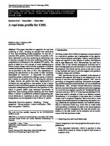
providers describe their hardware execution platform as a UML model library which is then annotated with HRM. Finally, the concepts introduced within the specific model library have to be used to describe hardware architecture. This model can be also annotated with HRM. Figure 8 illustrates a functional view of the Josefil hardware execution platform. We have described specific hardware resources such as ROM, RAM and AMD processor in a library which is then imported to describe a composite diagram of the Josefil architecture. This model is then annotated with specific Josefil hardware specification such as the RAM and the ROM memory sizes. For example in Figure 8, we give the sizes of the embeddedPC RAM (i.e. 64 MB) and ROM (32MB). In the same way, we provide the frequency of the AMD processor: 400 MHz. The Value Specification Language, introduced previously, is used again to specify the values related to the stereotype attributes. Allocation of the software elements presented in section 3.3 to this abstract representation of a hardware platform can be done in using allocation relationships. MARTE introduces this notion of allocation, which comprises spatial distribution and temporal scheduling aspects, between application elements and execution resource elements. Due to size limitation, this last part is not detailed in this paper.
Figure 8. An example of the Josefil hardware execution platform modeling
4.Experiment feedback Using MARTE to design the Josefil case study has provided significant benefits, compared to previous UML-based experiments. MARTE defines standard constructs to express non-functional properties, timerelated constraints and to describe execution platforms (software and hardware). Those modeling artifacts are essential concepts when designing real-time and embedded systems. In the current practices, this information is captured in the requirements of a
56
Authorized licensed use limited to: Baylor University. Downloaded on December 23, 2008 at 15:23 from IEEE Xplore. Restrictions apply.
5.Conclusion and Future Work
[4] S. Graf, I. Ober, and I. Ober. A real-time profile for UML. STTT, Software Tools for Technology Transfer, 8(2):113–127, April 2006 [5] L. Apvrille, J.-P. Courtiat, C. Lohr, P de Saqui-Sannes, A RealTime UML Profile Supported by a Formal Validation Toolkit, IEEE Transactions on Software Engineering, Vol 30, N° 7, pp 473-487, July 2004 [6] OMG. Systems Modeling Language (SysML) Specification. Object Management Group, Inc., Needham, MA 02494, May 2006. OMG document number: ptc/06-05-04 [7] OMG. UML Profile for Schedulability, Performance, and Time Specification. Object Management Group, Inc., Needham, MA 02494, January 2005. OMG document number: formal/05-01-02 (v1.1) [8] Object Management Group: Pending Issues sent to the OMG Finalization Task Force: UML Schedulability, Performance and Time profile. [9] Gérard S. (edited by): Report on SIVOES’2004-SPT Workshop on the usage of the UML profile for Scheduling, Performance and Time Mai 25th, 2004, Toronto, Canada. [10] OMG. MDA Guide (version 1.0.1) Object Management Group, Inc., Needham, MA 02494, June. 2003. OMG document number: omg/2003-06-01 [11] OMG. A UML Profile for MARTE (version beta 1) Object Management Group, Inc., Needham, MA 02494, August 2007. OMG document number: ptc/07-08-04 [12] Papyrus. Open Source Tool for Graphical UML 2 Modeling. http: //www.papyrusuml.org [13] Josefil. Challenge, http://www.ensieta.fr/mda/JOSEFIL [14] André C. Representation and Analysis of Reactive Behaviors: A Synchronous Approach. CESA’96, IEEE-SMC, Computational Engineering in Systems Applications, pp 19-29, Lille (F), July, 1996 [15] Thomas F., Gérard S., Delatour J., Terrier F., « Software RealTime Resource Modeling », Forum on Specification and Design Languages (FDL) 2007, ECSI, Barcelona, Spain, september 2007, p.231-236. [16] ARINC The Airlines electronic engineering committee, Avionics Application Software Standard Interface, ARINC Specification 653-1, Aeronautical radio, INC., Annapolis, Maryland, USA, October 2003 [17] OSEK The OSEK/VDX Group, OSEK/VDX OS specification, Version 2.2.3, http://portal.osek-vdx.org/files/pdf/specs/os223.pdf, 2005 [18] POSIX The Open Group Base Specifications, Portable Operating System Interface (POSIX), ANSI/IEEE Std 1003.1, 2004 [19] Taha S., Radermacher A., Gerard S., Dekeyzer J-L. « An Open Framlework for Hardware Detailed Modeling”, SIES’07 : Proceedings of the IEEE Second International Symposium on Industrial Embedded Systems, IEEE Computer Society, Lisbon, Portugal, 2007, p. 118-125. [20] System@tic competitiveness cluster project: Usine logicielle. http://www.usine-logicielle.org [21] Normand V., Exertier D., MDSysE: a Model-Driven Systems Engineering Approach at Thales, INCOSE Mid-Atlantic Researchers Conference, MARC 2004 (Baltimore, USA).
In this paper, we presented a first case study on modeling a RTES using MARTE. We discussed the details of the experiment and illustrated how key features of the MARTE profile have been used to specify real-time behavior and to design hardware and software execution platforms. Based on this first experiment, we have started another case study on a “real world” avionics system, in the context of a demonstrator for the Usine Logicielle project [20]. A key challenge for Thales is to enable early validation of a system design before the integration stages. Quantitative analysis provides interesting solutions (such as scheduling or performance analysis, either by the means of static analysis or simulation). However, analysis tools are not fully exploited today because they are not well enough integrated in the development process. Using a modelbased approach along with quantitative analysis techniques promises to achieve better results, as engineers do not have to extract analysis input from their design model, and then to deal with dedicated formalisms. The MARTE SAM and PAM profiles provide a specific support for these concerns in UML. We plan to exploit these features to validate the realtime behavior of our systems in the next stage of our experiments of MARTE. Model-based design using UML and SysML has proven its benefits to address System Engineering practices [21]. It is now a technology deployed on operational programs in Thales, in the domain of largescale distributed systems. By the means of supporting tools, the MARTE profile promises to foster the deployment of model-driven engineering in another key sector for Thales: the real-time and embedded market.
6.Acknowlegment The work presented here is partially carried out within the System@tic competitiveness cluster project Usine Logicielle. The authors do thank S. Taha for its valuable contribution to the hardware model of that case study.
7.References [1] OMG. Unified Modeling Language : Superstructure (version 2.1.1) Object Management Group, Inc., Needham, MA 02494, Feb. 2007. OMG document number: formal/2007-02-05 [2] CEA, I-Logix, Uppsala, OFFIS, PSA, MECEL, ICOM, UML based methodology for real time embedded systems, version 1.0, April 2003, Project IST 10069 AIT-WOODDES. [3] R.Ben Atitallah et al., Gaspard2 UML profile documentation, INRIA technical report RT-0342, http://hal.inria.fr/inria00171137/fr/
57
Authorized licensed use limited to: Baylor University. Downloaded on December 23, 2008 at 15:23 from IEEE Xplore. Restrictions apply.