MARTE: Also an UML Profile for Modeling AADL Applications Madeleine Faugère1, Thimothée Bourbeau1, Robert De Simone2 and Sébastien Gérard4 1 Thales Research and Technology, 2INRIA, 4CEA LIST {madeleine.faugere, thimothée.bourdeau}@thalesgroup.com,
[email protected],
[email protected] Abstract Marte (A UML Profile for Modeling and Analysis of Real-Time and Embedded systems) is a new UML profile extension for real-time and embedded systems, which is going to be standardized by mid 2007 at OMG (Object Management Group). This standard has been proposed by the “ProMarte” consortium, which consists of OMG end-users, tool providers and academics. Marte defines concepts in terms of UML extensions needed to model and analyze real-time and embedded systems (RT/ES). The Marte specification provides an annex which handles its relation to AADL-based models, and the way it may represent them.. Our purpose in this paper is to describe this relation. Our constructions will be presented and illustrated through some examples.
Hence, the OMG called for the development of a new UML profile for the Modeling and Analysis of RealTime and Embedded systems (Marte) [4]. The ProMarte consortium [5], set up to answer this RFP, consists of some main OMG end-users, tool providers and academics working on modeling in the real-time domain.
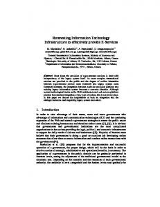
2. Marte in a nutshell As depicted in Figure 1, Marte architecture consists of three main packages. MARTE domain model
MarteFoundations
1. Introduction Some years ago OMG standardized the UML profile for Schedulability, Performance and Time specification (SPT) [1] to deal with real-time embedded (RT/E) aspects in a model-based approach.It contains a straightforward annotation mechanism, with a minimal set of usual annotations to perform basic quantitative analysis (essentially RMA schedulability and performance analysis based on queuing theory). Nevertheless, SPT structure was not flexible enough to allow for new user-defined annotations, or for other analysis techniques. Experiments using the profile led to a significant number of proposals for improvement and consolidation [2, 3], which were deemed too disruptive for a mere revision scheme. This included also new requirements for specifying both software (middleware) and hardware platform resources, MDA compliance for separate description of the platform and the application to be allocated on it, and modeling of all kinds of non-functional properties (NFPs) such as time, but also power consumption or memory size.
MarteDesignModel
MarteAnalysisModel
Figure 1. Marte architecture model
The Marte Foundations package defines all basics concepts required for model-based design and analysis of RT/Es. More precisely, it contains concepts for modelling: non-functional properties (called NFP), time-related concepts (dense or discrete, physical or logical), a general component model (GRM) for applications and a general resource model for platforms, together with an allocation notion to map the former on the latter (largely borrowed from SysML).. The GRM, itself a refinement of UML structured classes on top of which a support SysML blocks has been added, provides a common denominator for various models of computation and communication (MoCCs), and in principle does not target exclusively the real-time and embedded domain.,The objective of inter-relating with Lightweight-CCM, AADL and EAST-ADL2
12th IEEE International Conference on Engineering Complex Computer Systems (ICECCS 2007) 0-7695-2895-3/07 $25.00 © 2007 Authorized licensed use limited to: Baylor University. Downloaded on December 12, 2008 at 22:31 from IEEE Xplore. Restrictions apply.
formalisms has also influenced in some ways the definition of GRM. The MarteDesignModel covers what is usually called the left (descending) branch of a classical V cycle process, from requirement capture to specification, design and implementation. For this purpose it provides two main families of concepts: high level concepts for modeling both quantitative and qualitative features of RT/ES, and lower level concepts dedicated to be used for describing both hardware and software resources used for an application to execute. For precisely, the software resource model provided by Marte is not intended to define a new API for real-time operating systems but to enable users to describe model libraries of RTOS API in order to use these latter in for example multi-tasking design of their RTES. Marte provides also in one of its annexes such example of model libraries for ARINC and POSIX/VDX. The MarteAnalysisModel defines specific model abstractions and relevant annotations to be used by external tools in dedicated analysis techniques. It is split in three packages according to the kinds of analysis meant. The first one defines general concepts for quantitative analysis techniques; extendable to support new analysis techniques of RT/E UML models. The other two packages focus respectively on schedulability and performance analysis.
3. AADL in a nutshell AADL (Architecture Analysis and Design Language) is a SAE standard [1] for modeling system architectures of RT/ES. AADL mostly addresses data flow synchronous design in the form of thread and processes interacting through port connections, program calls and shared data access. This high-level application model is then mapped onto an execution platform consisting of processors, I/O devices, buses and memories. AADL uses here the word binding in place of AADL/Marte “allocation”. Bindings can be alternatives, thereby enhancing the general design architecture with implementation choice information. Time annotation on the application (mostly but not exclusively of periodic tasks nature) and on the execution platform allows for scheduling analysis techniques as in Marte. In the sequel we shall show how to represent in Marte the main concepts underlying AADL design styles, which will be listed then.
4. Marte and AADL cohabitation: the benefits for end-users
As opposed to Marte, AADL is a very specific and constrained language: 1) a specific abstraction layer in the development life cycle is addressed (software components mapped on hardware components), and earlier design stages can’t be covered by AADL language features; 2) the AADL execution platform model is based on a specific thread execution automata that needs to be fully comprehended by the end users and modelers. The domain application semantics must be in line with this thread execution semantics if to make sense; 3) non-functional properties come as a mere decoration of component specifications, and a better model integration would greatly improve endusers application modeling understanding. Using Marte for modelling AADL applications allows designers to model applications at earlier design stages; these models can be completed from different point of views (time properties, performance and scheduling features, hardware and software resources modelling information) making the application understanding easier. The designer would then take benefit from verification and validation tools and techniques connected to Marte based tools. For applications aligned with AADL semantics, using the Marte/AADL profile to customize its application would make the designer benefit from existing AADL validation and verification techniques and tools to validate analysis aspects for example. These validation/verification aspects would come as complement of the Marte based ones.
5. MARTE: Also an UML profile for modeling AADL-based applications AADL language allows describing static architecture features through software and hardware components as well as dynamic ones through data flows specification and configuration changes based on component interactions.
5.1. AADL software components The application run-time behavior of an AADL system is described through AADL Software components that are process, thread, thread group, data and subprogram. Process represents a unit of protected address space, containing at least one thread. These threads can be logically organized in thread groups, each group type capitalizing features and specific subcomponent accesses to other components declared outside the group. Data components represent static data and data types within a system. Subprogram components represent sequentially executable source code. The first four components will be modeled as
12th IEEE International Conference on Engineering Complex Computer Systems (ICECCS 2007) 0-7695-2895-3/07 $25.00 © 2007 Authorized licensed use limited to: Baylor University. Downloaded on December 12, 2008 at 22:31 from IEEE Xplore. Restrictions apply.
UML or Marte Classifier stereotyped defined in table 1 and subprogram components are represented as an UML Operation. AADL Marte Process «ComputingResource» Thread «Sw_SchedulableRessource» ThreadGroup “ThreadGroup” stereotyped UML Classifier Data “Data” stereotyped UML Classifier Subprogram “Subprogram” stereotyped UML Operation on a UML Classifier Table 1. Software components
5.2. AADL hardware components AADL hardware components are used to model the execution platform in terms of processors, memories, buses, and devices. A processor is an abstraction of the hardware and software that is responsible for scheduling and executing threads; it may contain memories. A memory represents an execution platform component that stores binary images. Devices represent components that interface with the external environment (sensors as well as more evolved components for example). A bus represents a communication channel, providing access between processors, memories and devices. Subprograms, data and processes are bound to memory components for being accessed by processors when executing threads. Hardware components will be modeled as UML or Marte classifier stereotyped as defined table 2. Specific data or bus accesses will be modeled by the way of interfaces provided by these components. AADL Processor Memory Bus Device
Marte «HwProcessor» «HwMemory» «HwBus» «HwDevice»
Table 2. Hardware components
Each hardware and software component is specified on the same frame, characterized by features, flow specifications, subcomponents, subprogram calls, connections, flow modes, and property characteristics. As each component owns a specific semantic, each one is characterized by a set of constraints restricting its possible configuration. An exhaustively implemented Marte UML profile for AADL with OCL constraints will greatly help the end-user to model a syntaxically correct AADL application.
5.3. Declarations and implementations In AADL, each component is characterized by a component types and component implementations. Component types define the externally visible characteristics seen and able to be used by other components. Component implementations define the component internal structure in terms of subcomponents, subcomponent connections, subprogram call sequences, modes, and flows. Like in UML, there can be several component implementations satisfying a same component type. For modeling AADL applications, we decided to model component declarations and implementations in different packages. Declaration and implementation types will be linked as defined figure 1 by UML realization and generalization links. UML semantic is sufficient to express the AADL implementation and extension concepts.
Figure 2. Declaration and implementation relations
5.4. Modeling topologies with ports and connections One of the AADL language characteristics is to enhance the architecture description with analysis information in order to perform end-to-end latency analysis for example. AADL is based on component connections through ports providing a communication media for data flow paths. As component containment and connection have to be addressed ,Marte proposes to model the subcomponent relationship through UML Parts, ports through UML ports on UML Parts or UML classes and connections through UML delegation connectors. Threads, processors, devices as well as their allowed subcomponents (process, system, threads group) can have different kind of ports for communicating unqueued data (through data ports: stereotyped ports), raised events (through event ports: stereotyped ports), or both events (through event data ports:
12th IEEE International Conference on Engineering Complex Computer Systems (ICECCS 2007) 0-7695-2895-3/07 $25.00 © 2007 Authorized licensed use limited to: Baylor University. Downloaded on December 12, 2008 at 22:31 from IEEE Xplore. Restrictions apply.
stereotyped ports). Figure 3 illustrates a process “control_speed_impl” composed of too threads connected by the way of a delayed connection.
flows represent subprograms and threads, UML pins stay for parameters and activity edges for connections.
Figure 5. Parameter connections
5.5. Subprogram call
Figure 3. Ports and connections
While designing large hierarchical applications, grouping ports in groups makes models more readable. Outside the components, a group can be connected as a single unit, and inside the component, ports can be connected individually to other ports. The only way to satisfy these constraints in UML is to design the port group as an UML part connected to on one side to the externally visible port and on the other side to other subcomponent parts as shown figure 4.
Subprogram calls are declared through call declarations within a thread or subprogram implementation. As subprograms are designed as UML operations, subprogram calls are designed through message calls in sequence diagrams (Figure 6).
Figure 6. Subprogram calls
5.6. Mode
Figure 4. Port groups
Connections are used to define several topologies between different software components, interacting differently according specific modes. They are three types of connections, 1) data, events or event data flows on port connections between components as presented above, 2) call-return interactions on subprogram entry points by the way of parameter connections and 3) access to shared data components. As these connections are defined at different model elements, classifier and parameters, a unified representation as port connectors is not possible. To represent parameter connections (Figure 5) , the use of activity diagrams is the sole solution: UML object
An interesting feature of the AADL language is to allow configuration (different component interactions) and configuration switching descriptions. So, a system is composed of different application configurations, one being active at a given time. Each configuration can have different active threads, different port and parameter connections, different subprogram calls, and different execution platform bindings. Each configuration is associated to a mode, and the transition from one mode to the other is triggered by events. The difficulty is to translate in a UML end-user friendly way this configuration changes based on events. The AADL graphical representation is very expressive and intuitive as shown Figure 5.
12th IEEE International Conference on Engineering Complex Computer Systems (ICECCS 2007) 0-7695-2895-3/07 $25.00 © 2007 Authorized licensed use limited to: Baylor University. Downloaded on December 12, 2008 at 22:31 from IEEE Xplore. Restrictions apply.
Figure 9: Mode switching Figure 7. Configuration change in AADL graphical language
Connections between parts and composite structures describe all possible connections. Each mode specific configurations will be described by the way of an UML Collaboration Use, named in line with the associated mode name as shown Figure 8.
5.7. Flows A flow specifies the detailed description and analysis of an abstract information path through a system. An end-to-end flow is composed of a flow source, a flow sink, flow paths inside component implementations, and connections outside components. Flow sources, flow sinks and flow paths are represented as activity diagrams, connected by object flows representing the connections between them as shown Figure 11. Figure 10 illustrates the infrastructure supporting the logical flow defined on figure 11.
Figure 10. Component connections
Figure 8: Configurations and modes
Mode switch triggered by events are represented by a state diagrams (see Figure 9), each state representing a mode, each transition representing mode change triggered by events. As events are raised by component implementations and communicated by ports, a logical link between the corresponding port and state machine needs to exist to be AADL compliant. For this, he usually use of UML transition will be turned away in the sense that the triggered event will be prefixed by the associated component and port name. The actions activated by the transition (see “change to flight mode” and “change to ground mode” methods) are part of the model to facilitate model readability; they will not be used during AADL code generation for example.
Figure 11. End-to-end flow specification
6. References [1] Object Management Group, UML Profile for Schedulability, Performance, and Time, Version 1.1. 2005, OMG document, formal/05-01-02, 2005. [2] Object Management Group, Pending Issues sent to the OMG Finalization Task Force: UML Schedulability, Performance and Time profile. [3] S. Gérard, Report on SIVOES’2004-SPT Workshop on the usage of the UML profile for Scheduling, Performance and Time, 2004, Toronto, Canada.
12th IEEE International Conference on Engineering Complex Computer Systems (ICECCS 2007) 0-7695-2895-3/07 $25.00 © 2007 Authorized licensed use limited to: Baylor University. Downloaded on December 12, 2008 at 22:31 from IEEE Xplore. Restrictions apply.
[4] Object Management Group, UML Profile for Modeling and Analysis of Real-Time and Embedded systems (MARTE), RFP. 2005. OMG document: realtime/0502-06. [5] The ProMARTE home page: http://www.promarte.org [6] SAE Standard, “Architecture Analysis and Design Language” (AADL), document AS5506/1, June 2006 [7] F. Thomas, H. Espinoza, S. Taha, S. Gérard, « MARTE » : le futur standard OMG pour le développement dirigé par les modèles des systèmes embarqués temps réel. [8] P. Feiler, D. Gluch, J. Hudak, B. Lewis, “Embedded Systems Architecture Analysis Using SAE AADL”, SEI Report, June 2004. [9] Singhoff F, Nana L et Legrand J., “Implementing an AADL performance analyzer”, DASIA 2006 Conference, European Space Agency Publication Division – Berlin, Mai 2006. [10] H. Espinoza, J. Medina, H. Dubois, S. Gerard, F. Terrier, “Towards a UML-based Modeling Standard for Schedulability Analysis of Real-time systems“, in MARTES: Modeling and Analysis of Real-Time and Embedded Systems International Workshop, Genova, 2006. [11] Ch. André, A. Cuccuru, R. de Simone, Th. Gautier, F. Mallet, and JP. Talpin , “Modeling with logical time in UML for real-time embedded system design” , in in MARTES: Modeling and Analysis of Real-Time and Embedded Systems International Workshop, Genova, 2006.
12th IEEE International Conference on Engineering Complex Computer Systems (ICECCS 2007) 0-7695-2895-3/07 $25.00 © 2007 Authorized licensed use limited to: Baylor University. Downloaded on December 12, 2008 at 22:31 from IEEE Xplore. Restrictions apply.