FIRST RESULTS OF AN EXPERIMENT ON ADVANCED COLLIMATOR. MATERIALS AT CERN HIRADMAT FACILITY*. A. Bertarelli, O. Aberle, R. Assmann, ...
Proceedings of IPAC2013, Shanghai, China
THPFI046
FIRST RESULTS OF AN EXPERIMENT ON ADVANCED COLLIMATOR MATERIALS AT CERN HIRADMAT FACILITY* A. Bertarelli, O. Aberle, R. Assmann, E. Berthomé, V. Boccone, F. Carra, F. Cerutti, C. Charrondiere, A. Dallocchio, M. Donzé, P. Francon, M. Garlaschè, L. Gentini, M. Guinchard, N. Mariani, A. Masi, P. Moyret, S. Redaelli, A. Rossi, CERN, Geneva, Switzerland M. Calderón Cueva, Universidad San Francisco de Quito, Quito, Ecuador, N. Charitonidis, EPFL, Lausanne, Switzerland, L. Peroni, M. Scapin, Politecnico di Torino, Turin, Italy A comprehensive, first-of-its-kind experiment (HRMT14) has been recently carried out at CERN HiRadMat facility on six different materials of interest for Beam Intercepting Devices (collimators, targets, dumps). Both traditional materials (Mo, W and Cu alloys) as well as advanced metal/diamond and metal/graphite composites were tested under extreme conditions as to pressure, density and temperature, leading to the development of highly dynamic phenomena as shock-waves, spallation, explosions. Experimental data were acquired, mostly in real time, relying on extensive integrated instrumentation (strain gauges, temperature and vacuum sensors) and on remote acquisition devices (laser Doppler vibrometer and high-speed camera). The experiment was a success under all points of view in spite of the technological challenges and harsh environment. First measurements are in good agreement with results of complex simulations, confirming the effectiveness of the acquisition system and the reliability of advanced numerical methods when material constitutive models are completely available. Valuable information has been collected as to thermal shock robustness of tested materials.
acquired relying on integrated instrumentation (strain gauges, temperature probes and vacuum sensors) and on remote-acquisition devices (laser Doppler vibrometer and high-speed camera) [8].
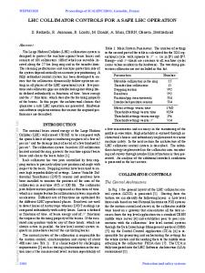
HRMT-14 LAYOUT AND INSTRUMENTATION The material sample holder consisted of a vacuum vessel and a specimen housing featuring 12 material sample tiers arranged in two arrays of six (Fig. 1). The housing could be accurately positioned via a two degreeof-freedom actuation system: the 300-mm vertical travel permitted to centre on the beam axis each of the six tiers, while the 120-mm lateral movement allowed switching between the two arrays. Specimens were made of materials currently used for BID such as Inermet® 180 (tungsten heavy alloy), Glidcop® AL-15 LOX (dispersion-strengthened copper) and Molybdenum, as well as novel materials under development (Molybdenum-Copper-Diamond, CopperDiamond and Molybdenum-Graphite composites) [9].
INTRODUCTION The commissioning in recent years of new, extremely energetic particle accelerators such as the LHC [1] required the development of advanced methods to predict the behaviour of Beam Intercepting Devices (BID) in case of direct beam impact. Such events can at times be studied with standard implicit FEM codes [2],[3] and, in the elastic regime, even with analytical methods [4],[5]. However, at high energy densities, phenomena like changes of phase, fragment ejection, explosions usually occur; in this case, one has to resort to advanced explicit wave propagation codes like Autodyn or LS-Dyna [6]. These numerical tools require accurate material models which are often incomplete, especially for nonconventional alloys or composites. In order to probe and validate such models, a first-of-its-kind experiment was recently carried out at CERN HiRadMat facility [7], entailing the controlled impact of intense proton pulses on specimens made of six different materials for BID. For a comprehensive characterization, experimental data were ___________________________________________
*Work supported by the European Commission under the FP7 Research Infrastructures project EuCARD, Work Package 8, ColMat
07 Accelerator Technology and Main Systems T19 Collimation
Figure 1: General assembly and specimen housing detail of the HRMT-14 test-bench. Two different specimen shapes were chosen for each tested material: cylindrical disks (type 1) for mediumintensity tests, to measure axially-symmetric shockwaves; cylinders with a half-moon cross section (type 2) for highintensity tests, allowing extreme surface phenomena (melting, material explosion, debris projections etc.) to be visualized and optically acquired. The number of specimens per tier varied as a function of the radiation and nuclear interaction lengths of the sample material. ISBN 978-3-95450-122-9
3391
c 2013 by JACoW — cc Creative Commons Attribution 3.0 (CC-BY-3.0) Copyright ○
Abstract
THPFI046
Proceedings of IPAC2013, Shanghai, China Experimental measurements and numerical simulations were compared, both at medium and high intensity. Numerical simulations adopted the same parameters of the experiment, with the exception of the beam transverse dimension initially assumed to be 2.5 x 2.5 mm2. Table 1: Beam Parameters for Tests at Medium Intensity on Glidcop® AL-15 and High Intensity on Inermet® 180
Figure 2: Material specimen shapes for medium intensity (type 1 - left) and high intensity (type 2 - right). The vacuum vessel was equipped with view ports housing a transparent optical window, designed to withstand internal vacuum and particle projections (Fig. 3). One view port allowed the transmission of a laser beam for the Laser Doppler Vibrometer (LDV) measurements of type 1 specimens. A second port was reserved for the acquisition by a high-speed camera of images of type 2 samples while exposed to high-intensity shots. The vessel was equipped with UHV beryllium windows at the beam entry and exit ports.
Medium intensity
High intensity
Material
Glidcop® AL-15
Inermet® 180
Proton energy
440 GeV
440 GeV
Number of bunches 72
72
Bunch spacing
25 ns
25 ns
Pulse intensity Energy on the most loaded specimen
4.66e12 protons
9.05e12 protons
9.8 kJ
25.1 kJ
Impact point
Centre of type1 specimen
2 mm from type2 sample flat part
Beam transverse dimension ()
1.3 x 1.3 mm2
1.9 x 1.9 mm2
c 2013 by JACoW — cc Creative Commons Attribution 3.0 (CC-BY-3.0) Copyright ○
Medium-energy Tests, Results on Glidcop®
Figure 3: Assembled test-bench with instrumentation cables and connectors (left); strain gauges mounted on type 1 specimens (right). Part of the instrumentation was installed directly on the specimens; resistive strain gauges measured the strain produced on samples by shockwave propagation, to benchmark time-dependent simulations (Fig. 3). Axial and circumferential strains were acquired at a sampling frequency of 4 MHz, with amplitudes up to 20.000 m/m. Temperature sensors, vacuum pressure gauges and microphones were also installed inside or in the vicinity of the tank. All embedded components had a resistance before failure higher than 250 kGy (10 times the expected prompt dose) [10]. LDV and high-speed camera were installed remotely, in a concrete bunker, in order to protect them from the effects of radiation; signals were sent through a set of precisely aligned mirrors. The LDV acquired the radial velocity on the outer surface of one cylindrical sample per tier. The high-speed camera filmed the particle projection produced by beam impacts on type 2 specimens; lighting necessary for the acquisition was provided by a battery of radiation-hard xenon flashes mounted atop the tank [11].
PRELIMINARY RESULTS A very large amount of data was acquired during the experiment and is currently under intense post-processing.
ISBN 978-3-95450-122-9 3392
In Fig. 4, hoop strains obtained from simulation are compared to values measured by three strain gauges placed on the external surface of Glidcop® specimens, circumferentially spaced by 90˚: in principle, given the axial symmetry of load and geometry, the three measurements should superpose. Differences in acquired values are probably mainly due to the noise on cables and gauges during the acquisition as well as to errors on the beam impacting position. It is also interesting to note that electromagnetic noise induced by the particle beam perturbed the strain gauge measurements during a few microseconds after the impact, concealing the first deformation peak; however, this interference died out immediately after, allowing to capture the remainder of the phenomenon.
Figure 4: Hoop strain: comparison between measurements, three dotted lines, and numerical model, solid line (left); radial velocity measured by the vibrometer, dotted blue, and simulated, solid black (right).
High-energy Tests, Results on Inermet® 180 The high-speed camera system allowed for the first time, to the best of authors’ knowledge, to record images of the impact of a proton beam on solid targets and of the effects induced.
07 Accelerator Technology and Main Systems T19 Collimation
Proceedings of IPAC2013, Shanghai, China
THPFI046
CONCLUSIONS AND FUTURE ACTIONS A complex and comprehensive experiment has been carried out at CERN aiming at the characterization, mostly in real time, of six different materials impacted by 440 GeV/c intense proton pulses. Preliminary measurements on Glidcop® AL-15 LOX and Inermet® 180 specimens well match results of advanced computations, providing encouraging indications on the validity of the constitutive models used for these materials. A large amount of data is being treated and will help deriving constitutive models for the less known composite materials. An extensive post-irradiation campaign, implying direct observations as well as nondestructive and destructive testing, is being launched to provide additional valuable information.
Figure 5: Image sequence of the impact on Inermet® 180 at high energy; three samples are partially visible. As shown in Fig. 5, a large quantity of hot material was ejected at high velocity from the two most loaded Inermet® 180 type 2 samples; the high temperatures reached are attested by the intense light emitted by the fragments during a few hundred microseconds.
Figure 6: Comparison between simulation (SPH method) and acquired image ~125 μs after the impact. Mesh-less simulation results are consistent with camera acquisitions (Fig. 6), even considering the differences in beam size between real and simulated scenarios. The acquired velocity of the fragment front is about 275 m/s, well matching the simulated velocity of 316 m/s.
' Figure 7. Post-mortem observation of Inermet® 180 samples (left) and simulated failure (right).
07 Accelerator Technology and Main Systems T19 Collimation
[1] The LHC Design Report, http://abdiv.web.cern.ch/ ab-div/Publications/LHC-DesignReport.html , July 2004. [2] A. Bertarelli et al., “Mechanical Design for Robustness of the LHC Collimators”, PAC’05, Knoxville, May 2005. [3] A. Bertarelli et al., “Permanent Deformation of the LHC Collimator Jaws Induced by Shock Beam Impact: an Analytical and Numerical Interpretation”, EPAC’06, Edinburgh, July 2006. [4] A. Bertarelli et al., “Dynamic Response of Rapidly Heated Cylindrical Rods: Longitudinal and Flexural Behaviour”, Journal of Applied Mechanics, May 2008, Volume 75, Issue 3, 031010, pp. 1-13. [5] A. Dallocchio, “Study of Thermo-Mechanical Effects Induced in Solids by High Energy Particle Beams: Analytical and Numerical Methods”, PhD Thesis, Politecnico di Torino, Turin 2008. [6] A. Bertarelli et al., “Limits for Beam Induced Damage: Reckless or Too Cautious?”, proc. Chamonix 2011: Workshop on LHC Performance, January 2011. [7] I. Efthymiopoulos et al., “HiRadMat: a New Irradiation Facility for Material Testing at CERN”, IPAC’11, San Sebastián, September 2011. [8] A. Bertarelli et al., “High Energy Tests of Advanced Materials for Beam Intercepting Devices at CERN HiRadMat Facility”, HB2012, Beijing, September 2012. [9] A. Bertarelli et al., “Research and Development of Novel Advanced Materials for Next-generation Collimators”, IPAC’11, San Sebastián, September 2011. [10] N. Charitonidis et al., “Radiological assessment of the Collimator Materials tests at HiRadMat in 2012”, EPFL-Report-178219. [11] A. Bertarelli et al., “An Experiment to Test Advanced Materials Impacted by Intense Proton Pulses at CERN HiRadMat Facility”, accepted for publication on Nuclear Instruments and Methods in Physics Research, Section B.
ISBN 978-3-95450-122-9 3393
c 2013 by JACoW — cc Creative Commons Attribution 3.0 (CC-BY-3.0) Copyright ○
REFERENCES