Roland Jung, Oirk Neet, Hugh O'Hanlon and Lucien Vos*. Summary. Each ring of the ISR is equipped with a collimator system consisting of 10 movable,.
© 1979 IEEE. Personal use of this material is permitted. However, permission to reprint/republish this material for advertising or promotional purposes or for creating new collective works for resale or redistribution to servers or lists, or to reuse any copyrighted component of this work in other works must be obtained from the IEEE.
IEEE Transactionson NuclearScience,Vol. NS-26,NO. 3, June 1979 THE CERN ISR COLLIMATOR SYSTEM Thys
Risselada,
Roland
Jung, Oirk
Neet,
Hugh O'Hanlon
and Lucien
Vos*
resonance
Summary with a collimator Each ring of the ISR is equipped consisting of 10 movable, remotely controlled, inside the vacuum system. One vertical and one horizontal collimator at the same azimuth limit the beam size during all machine operations. These primary collimators are followed at rr/2, 'II and 3fl/2 betatron which intercept phase advance by secondary collimators, the high energy protons scattered at small angles from the surface of the primary collimators by Coulomb forces. This system makes it possible to limit the beam dimensions without scattering protons into the downstream of the collimators. Consideraintersections ble improvement has been achieved in background and induced radioactivity conditions in all physics intersections. The properties of different metals with res-
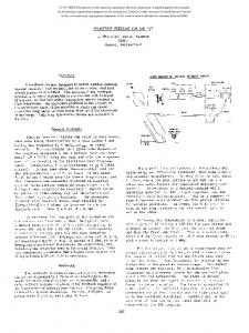
excitation, collisions with residual gas), distances to the edge are even smaller than 30 I.cm (Fig. ICI.
the
system blocks
pect to collimation, vacuum
temperature rise are discussed.
compatibility
1.
and ultrahigh
J////////////////////////////// ~:s”B~;:e 11
kraping
beam
\tdblT
Introduction
At the ISR the high energy physics experiments are in 6 out of the 8 intersections, with sensitive detectors close to the vacuum chamber, and are, therefore, sensitive to (il radioactivity induced during filling periods, and (ii1 to background caused by loss of protons from circulating beams during physics periods. installed
(
1
4
0 +
Fig.
40
0
Distance
to
1 Particle
edge
(mm) +
distribution
Distance
(used
to edge (‘+~mj
in calculations)
Due to controlled beam loss during the stacking (shaving and scraping1 for every Amp stacked, From circulating beams one Amp is lost in the machine. 107 to 108 protons are lost per second during physics runs.
These superficial impacts on the titanium block permit a significant part of the incoming protons to be scattered out of the block by multiple Coulomb scattering, without having any nuclear interaction with the stop the protons nuclei in the block which would either or scatter them with very large angle and momentum
Obviously, the losses of these large numbers of protons have to be concentrated in an area well away from the physics experiments. In the early years of the ISR the beam size was limited by the internal dump absorber block in the vertical plane, and by thin foil scrapers in the horizontal plane'. It soon became clear that this was insufficient, as a large number of protons escaped from these aperture limitations, wlthout being absorbed.
errors.
process
In 1974 a solution of placing vertical collimators downstream of the dump block was successfully tested. However, this was insufficient to cover the experiments in all intersections simultaneously and a study of a complete collimator system was undertaken.
A first
set of horizontal
collimators
was in-
in 1976, improving the protection of the most The system will be critical physics intersections. completed in March 1979, and is expected to protect the entire machine, the induced radioactivity and losses from circulating beams being concentrated in a small
The angle and momentum errors resulting from non-nuclear interactions only [Coulomb scattering and are so small that the larger part of the lonisationl Coulomb scattered protons can actually circulate over and be lost elsewhere around the machine. some distance Experience has shown that they can be extremely harmful to the high energy physics experiments, either as direct background or by inducing radioactivity in the intersection vacuum chambers. The conclusion was that with these superficial impacts, one single collimator (in this case the dump to stop protons with a high block) is not sufficient enough efficiency. In each plane the “primary” collimator has to be followed by "secondary" collimators.
stalled
area around the location each ring. 2.
of the internal
beam dump in
At the ISR protons are lost during filling periods The by scraping_ with thin foil scrapersl. internal dump absorber block, approximately l/4 betatron wavelength downstream of the scrapers, is placed by the against the beam to absorb protons scattered scraper blade, and to limit the beam size in the vertiIn this case the protons strike the block cal plane. less than 3 mrr away from the edge (Fig. 1 a and bl. In the case of protons lost from stable beams, where slow mechanisms are involved (intra-beam scattering, * CERN, Geneva, Switzerland
block
Computer calculations* were carried from blocks of different metals.
before
probability,
outscattering
the
mean path
occurs,
length
out on outThe outinside the
and the mean out-
scattering
angle have been computed for an ideal flat parallel to a 26 GeV proton of infinite length in the two cases of “scraping” and "stable beam".
block beam, The results
Theory of outscattering
mainly
scattering scattering
are summarised in
I.
The calculated outscattering probabilities are values and can only be obtained if the block is perfectly flat and at least as long as the calculated This allows a "mean path" for the particular metal. first selection of suitable collimator metals, which should have a low out-scattering probability and a short mean path [the available space is often limited). In this respect tungsten and molybdenum are the most attractive candidates.
minimum
4131 0018-9499/79/06oo-4131$00.75 0 1979IEEE
Metal
Outscattering Probability
Mean Path (mm1
(%1
Mean Angle
(mradl
plane and 3 in the vertical tional vertical collimator new ISR dump block4. The highest
SCRAPING
copper Steel
1.0 1.2
Tungsten Molybdenum Titanium
1.3 1.4 2,5
4.5 4.2 7.2 5.4 3.4
235 267 159 200 422
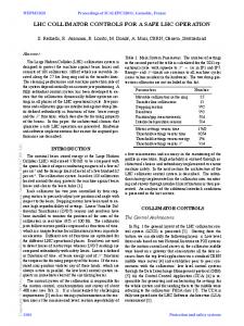
obtained when the seconclose to the circulating beam. It is essential that they do not actually touch the circulating beam, otherwise they would become a primary scatterer. A typical collimation curve is shown in fig. 3, representing the proton losses in the
is
37 38
Tungsten Molybdenum Titanium
30 39 42
Copper
I. Computer calculation properties of metals suitable for the input distributions Collimator
1.1 1.1
49 53 32 47 76
Table
system
of outscattering for collimation shown in Fig. 1
which
means that
the
Due to the betatron oscillations angle errors are into position errors at n/2 and 3~/2 phase position advanci. Momentum errors become horizontal errors at II phase advance, due to the shift in radial equilibrium orbit (Fig, 21. In the scraping case the momentum loss in the block is of the order of 1% for 26 GeV protons, as around 1 MeV is lost per mmdue to ionisation. BEAM (horizontal
- 80
plane1
Fig.
3 Proton vs.
n
losses
in first
-40
Cal>
3n/2
from primary
position
of horizontal
intersection collimator
downstream at 71
azimuths as defined above are not availaare a compromise The actual locations and the phase advances are slightly different from the ideal ones. This is shown in betatron phase space plots, where the acceptance of the vacuum chamber over 1 turn, the acceptance of the collimator system, and the beam are plotted. emittance block figures as a A collimator straight line, of which the slope corresponds to the betatron phase of the collimator location, and the distance to the origin represents the normalised distance of the block to the centre of the beam. The ideal
Ideally,
a horizontal collimator system of 4 blocks figures as a square, but for reasons above, the square may be distorted.
at n/2 intervals mentioned
The fact that the acceptance of the collimator system lies entirely inside the acceptance of the vacuum protected. chamber means that the chamber is completely In addition to protection against outscattering from the
collimator,
the system provides
also protection
against injection errors with any phase and against accidental changes of the closed orbit. A phase space system, valid for the currenplot of the ISR collimator tly used magnetic machine, is shown in Fig. 4.
block
Scattering
position
ble in the ISR.
primary n/2
-60
Collimator
for the ISR
required
transformed
2
a few mm wide,
Ir---‘-u ,
1.8 1.3 0.9
The momentum spread of an ISR circulating beam is an average horizontal aperture of about 3%, requiring 60 mm, whereas the average vertical beam height is only 6 mm. To limit the beam size in both planes 3 primary collimator blocks are therefore required: 2 horizontal As each of these [inner + outer1 and 1 vertical. blocks scatters in both planes, it is important that all primary collimators be located at the same azimuth. In this way, they can be backed up by one and the same system of secondary collimators.
Fig.
only
collimators have to be positioned with a precision better than 1 mm with respect to the beam.
Steel
Prim.
is
are positioned
first intersection downstream of the collimator system, versus the lateral position of the lr/2 collimator. The range over which the maximum efficiency Is obposition tained
STABLE BEAN :
3.
efficiency
dary collimators
:
plane per ring. An addiis mounted in front of the
block
The average angle and momentum errors result in position errors of several cm. A secondary block, placed at one of the above mentioned phase advance locations close to the beam will then be hit by protons escaping from the primary block at large distances from the edge. The probability of outscattering from the secondary block is therefore negligeable.
Secondary
are required at at lr/2 and 3n/2 downstream of the primary collimator, whereas in the vertical plane Ionly one double upper/lower collimator at n/2 is sufficient. at The momentum error collimator plane, at the inn is only required in the horizontal both
side
sides
of
horizontal
the
collimators
beam (inner/outer)
(low momentum side1 of the beam. mator system consists thus of 7 blocks 4132
A complete colliin the horizontal
Fig.
4 Betatron phase space plot of ISR horizontal collimator system valid for the injection orbit 4. The blocks
Blocks and Controls
are mounted
inside
the
ultra
high
vacuum
chamber. As the space, two types
design is constrained by the are insta lied of co1 limators
available :
al a sufficiently long block in straight sections between magnets. For vertical collimators a 300 mm long block can be mounted in this space, and 270 mm in plane. (Fig. 51. the horizontal block installed through a puma much shorter at the end of a main magnet vacuum chamber. In this case a block of only 130 mn mounted on a 500 mm long arm can be accommodated. This length is adequate only for secondary collimators.
size,
The optimum positions depend and may have to be adjusted
All
primary
blocks
have
a length
greater
than
270
mm. Choice of metal. The first [vertical) blocks inwere made of stainless steel. For the horizontal secondary collimators, including the short 130 mm blocks, tungsten was chosen for its short absorption length, given the limited space. stalled
The primary collimators, which were the last ones to be installed, will carry the heaviest thermal load. As sufficient available space could be found at these locations, the absorption length is not critical and Molythe metal was chosen for its vacuum properties. bdenum is preferred to tungsten for two reasons : the rate is about a magnitude lower, and the outgassing heat capacity is 50% larger for the same volume. Addiis not tional cooling of the primary molybdenum blocks necessary. The temperature of the primary blocks is monitored with thermocouples. A maximum temperature rise of 50°C is estimated to be compatible with the ISR ultra-high vacuum. Experience shows that during normal filling periods this value is not exceeded.
Controls. The blocks are moved by stepping motors and their position is monitored by resolvers. The system has been designed for computer control via CAMAC, with a simplified but complete manual back-up facility. The maximum displacement speed has been set to 6 m-n/s, acceleration and deceleration cycles. with proper The blocks can be moved in 5 pm steps under computer control or manually in 40 lirn increments. Resolvers are used to measure the position with a precision better Multiplexed controls than 20 pm over a 50 mm stroke. are used, resulting in minimum cost for cables and
beam
The small step size (5 pm1 permits collimator fine adjustments at any time, without risk of causing large background splashes which could damage the wire chambers in the physics experiments.
6.
bl
ping port
on the actual occasionally.
Results
The vertical secondary collimators have been in use since 1974, and have reduced backgrounds by as much as a factor of 20 during stable beam periods, particularly in the intersection downstream of the dump block in each ring, where very sensitive experiments are located. They are, however, less efficient during inposition of the injected jection, due to the eccentric beam in the vacuum chamber. The horizontal rr/Z collimators, installed in 1977, have reduced the losses during the injection and stacking cycle in the intersections downstream of the dump block by a factor 10 to However, it was often not possible to pro20 (Fig. 31. tect the other physics intersections with the same efficiency. It is expected that with the complete system, all intersections will be equally protected.
Dosimeter results3 show that since the installation of the horizontal collimators, the integrated proton losses
around
the
region pose.
of the
collimator
rings
7.
have decreased, except in system, dedicated to this
the
pur-
Acknowledgements
We are indebted to F. LeNormand for the vacuum tests of the tungsten and molybdenum blocks. The provertical collimators in 1974 was made posal to install by K. Potter and S. Turner. The collimators were designed and built by J. Genest and A, Maurer. The A. Marelectronic equipment was built by I. Barnett, chand, H. Kropf and J-N. Vouillot, and the computer control software by P. Nartucci.
0. B.W. Montague 11 CERN-ISR-DI/71-51. 21
T. Risselada:
internal
report
References
: Beam Scraping
Targets
Multiple Scattering CERN-ISR-OP/77-16,
at the
ISA,
and Collimation,
electronics. The displacements are interlocked with a beam loss detector, to avoid beam loss and damage to the collimator block surface.
5. The collimator
Operational blocks
have
Dosimetrie a&our des A. Per-rot and P. Bouriot: 31 report CERN-ISR-BOM/78-5, and CERN-ISRISR, internal BON/79-9. 41 high
Use to be positioned
C. Hauviller: intensity
The ISR new absorber blocks beams, this Conference (J-421.
for
with
precision with respect to the circulating beam. During the set-up the optimum positions of the inner horizontal and of the vertical blocks are derived from made with a single pulse on a closed orbit measurement the injection orbit. A computer program, using harcalculates the posimonic analysis and interpolation, high
tion
of the
beam centre
and the
beam size
at
each colli-
mator and positions the blocks at a pre-set distance from the beam envelope. The blocks are kept at these during the entire filling period. positions During
stable beam periods, when the orbits are not known precisely, the collimator positions are optimised manually, using the background signals from scintillator counters in the intersections.
generally
Fig.
5 Horizontal
Collimator
Block
4133