9th Annual Conference of the International FES Society September 2004 – Bournemouth, UK
Flexible microelectrode arrays with integrated organic semiconductors Feili D 1, Schuettler M 2, Stieglitz T 1 1
Neural Prosthetics Group, Fraunhofer Institute for Biomedical Engineering, Ensheimer Str.48, D-66386, St. Ingbert, Germany 2 Implanted Devices Group, University College London, 11-20 Capper Street, London EC1E 6JA, UK Email:
[email protected]
Abstract Biomedical microimplants offer the potential to restore body functions after paraplegia by means of functional electrical stimulation (FES). This paper describes the development of a flexible biomedical microimplant for FES use with integrated organic semiconductors. The microelectrodes array is based on flexible polyimide substrate, uses gold as metalization layers, pentacene as organic semiconductor and parylene C as encapsulant. A 3x3 microelectrode array has been fabricated and characterized. The device worked properly on the bench. Investigations on the electrical properties showed promising results.
1
trough each electrode using a thin-film field effect transistor (FET). In this work, we investigated this possibility using an organic polymer semiconductor material, which processing steps were implemented in already established processes for making polymerbased microelectrode arrays. 1
2
3
1
Introduction
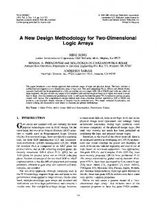
Roughly 600,000 people in Europe have incurable diseases of the retina such as Retinitis Pigmentosa or Macular Degeneration, which finally lead to blindness. In the organ of vision (the eye) there are 2×10⁸ receptors that can determine about 4×105 pixels. To stimulate electrically this organ [1] a tremendous high number of electrodes seems to be required. Increasing the number of electrodes in a multichannel microelectrode system at given anatomical space is one of the essential problems related to stimulating this organ. So far, each electrode has to be connected via a separate cable to the implant electronics [2] or relatively thick and stiff silicon based circuitry has to be used [3]. Polymer electronic technology has the potential to integrate circuits on microelectrodes and thereby overcomes the limitations of traditional FES systems and microimplants. A method to reduce the number of wires required for a microelectrode array is matrix addressing. In this method, only two lines can activate each element in an array. The advantage is that in an N×M electrode matrix, instead of N×M interconnects, only N+M interconnects are needed (figure 1). It should be possible to control the current, which flows
2
3
Stimulation Electrode
Counter Electrode
Figure 1: A 3×3 electrode array controlled by a FET matrix.
2
Materials and Methods
The used material has to be biocompatible and should not, either directly or through the release of their material constituents, produces toxic, injurious, or immunological response or rejection in living tissue. Therefore, the electrodes will be based on a flexible polyimide substrate. Highly flexible polyimide based microdevices that have been interfaced with nerves as neural prostheses showed excellent properties as implant material [4]. In order to protect the implants from the harsh environments in the human body (e.g. saline solution, blood, etc.) and to ensure the electrical functionality of implants (insulation), the implant is encapsulated in biostable parylene C. The potential of organic and polymeric electrically active molecules in flexible electronic recently aroused the interest of research. Different types of organic materials have been used to make organic FETs [5]. One of the most successful materials under investi-
9th Annual Conference of the International FES Society September 2004 – Bournemouth, UK
gation is pentacene. It was demonstrated that carrier mobility for organic pentacene is about 2.1 cm2/Vs [6]. Which is comparable to mainstream α-Si:H thin film transistor (TFT) technology. This encouraged us to use pentacene as organic semiconductor material.
2.1
Electrode Array Design
Using the theory for the isolated gate field effect transistor, introduced by Ihantola and Moll [7], the drain current for the TFT can be calculated with equation 1. IDsat. = (W/2L) Ciµ(VG-VT)2 with:
: charge carrier mobility : insulator capacitance per unit area : channel length : channel width : threshold voltage : gate-source voltage
According to the theory the drain current depends on the relation of channel length to channel width of transistor. Therefore the structure has to have a channel length to channel width ratio as large as possible. A loop structure led to ratio of channel width (10 µm) to channel length (51,520 µm) of over 5000. Figure 2 shows the designed electrode array.
Gate
Electrode
Parylene
µ Ci L W VT VG
Equation 1
and a lift-off process on the polyimide, to build the gate electrode. As insulator layer an 800 nm thick polyimide layer was spun on. On top of this insulation layer, a 300 nm Ti/Au layer was sputtered and patterned which works as drain and source. Upon drain and source contacts, an 80 nm thick layer of pentacene (C14H22) was thermally evaporated in ultra high vacuum environment with a substrate temperature of 75°C and a deposition rate of 1 Å/s. A 10 µm layer parylene C was deposited from the vapour phase at room temperature on the pentacene. An aluminium etching mask of 200 nm was sputtered onto the parylene C and structured photolithographically. After 2.5 hours of reactive ion etching with oxygen plasma at 300 W, the contact pads and electrode sites are opened (figure 3). Contact Pads
Pentacene Source
Drain
Polyimide Gate Polyimide
Figure 3: Schematic view of a flexible transistor (cross section).
3
Results
Microelectrode arrays with integrated organic FETs were produced using pentacene as semiconducting layer. The electrical properties of these transistors were characterised using a custom made setup.
Source
-5
-2,5x10
-5
A
B
Drain
1.7 mm
Figure 2: A: 3×3 electrode array B: Single transistor structure
2.2
Process Technology
A silicon wafer was used as mechanical carrier for the processing of thin film structures. On this wafer a 5 µm thick polyimide layer (Pyralin 2611) was spun on and cured at temperature of 350 °C under nitrogen atmosphere. A 300 nm gold layer was deposited by sputtering and patterned by photolithography
I Drain/Source (Amp.)
-2,0x10
Vgs = -30 V Vgs = -25 V Vgs = -20 V
-5
-1,5x10
-5
-1,0x10
-6
-5,0x10
0,0 0
-5
-10
-15
-20
-25
-30
-35
-40
-45
-50
V Drain/Source (Volt)
Figure 4: IDS versus VDS
The drain-source current IDS was measured versus the drain-source voltage VDS at different gate-source voltages VGS (figure 4). Furthermore the drain-source current was measured
9th Annual Conference of the International FES Society September 2004 – Bournemouth, UK
versus the gate-source voltage at different drain-source voltages (figure 5). The transistors show a maximum drain source current IDS of about 15 µA for VDS of –30 V and VGS of -30 V.
-5
-3,5x10
-5
I Drain/Source (Amp.)
-3,0x10
-5
V ds = -60 V V ds = -40 V V ds = -20 V
-2,5x10
-5
-2,0x10
-5
-1,5x10
5
We fabricated flexible organic electronic circuits integrated into a microelectrode array, which could be used in FES micro implants. The polyimide-based device is encapsulated in biocompatible parylene C. The electrical properties of the organic FET at room temperature in dry environment are promising and show the potential of organic electronics for use in microimplants. However, the efficacy of the FETs has to be improved and their performance in wet environment has to be investigated.
-5
-1,0x10
References
-6
-5,0x10
[1]
Thompson RW, Barnett MS, Humayun G, Dagnelie G. Facial recognition using simulated prosthetic pixelized vision. Investigative Ophthalmology & Visual Science vol 44, no 11: 5035-42, 2003.
[2]
Suaning GJ. Fabrication of platinum spherical electrodes in an intra-ocular prosthesis using high-energy electrical discharge. Sensors and Actuators A, vol 108: 155-161, 2003.
[3]
Schwarz M, Single chip CMOS imagers and flexible microelectronic stimulators for a retina implant system. Sensors and Actuators A, vol 83; 40-46, 2000.
[4]
Stieglitz T, Beutel H, Meyer J-U. A flexible, light-weight multichannel sieve electrode with integrated cables for interfacing regenerating peripheral nerves. Sensor and Actuators A, vol 60: 240 – 243, 1997
[5]
Dimitrakopoulos CD, Mascaro DJ. Organic thin film transistors: a review of recent advances. IBM J. Res. & Dev., vol 45, no 1: 11 - 27, 2001
[6]
Gundlach DJ. Organic thin film transistors with field effect mobility > 2 cm2/Vs. 57th device research conference digest, vol 1: 164 – 165, 1999.
[7]
Ihantola HKJ, Moll JL. Design theory of a surface field-effect transistor. Solid-State Electronics, vol 7: 423-430, 1964.
[8]
Dimitrakopoulos CD. Molecular beam deposited thin film of pentacene for organic field effect transistor applications. J. Appl. Phys., vol 80, no 4: 2501-2508 ,1996.
[9]
Wang J, Gundlach DJ. Improved contacts for organic electronic devices using selfassembled charge transfer materials. 41st Electronic Materials Conference Diges", vol 1: 16, 1999.
0,0 10
0
-10
-20
-30
-40
-50
V Gate/Source (Volt)
Figure 5: IDS versus VGS
4
Conclusion
Discussion
Microelectrode arrays with integrated organic semiconductors have been fabricated on polyimide substrates using pentacene as active layer. Choosing a high ratio of channel width to length, we obtained a drain-source current in the range of 20 µA. To do so, the gate-source voltage as well as the drain-source voltage were relatively high in the range of 30 to 40 V. Pentacene is a small molecule that consists of five benzene rings. In crystal form the molecules stand up vertical on the substrate. The mobility of charge carriers and therefore the maximum achievable drain current depends on the molecular crystal structure and morphology of the pentacene. Substrate morphology, substrate temperature, pentacene deposition rate and process pressure are important parameters that influence the molecular crystal structure and morphology of pentacene crystal and affect therefore the maximum achievable drain current [8]. The relatively high drain and gate voltages required for obtaining reasonable drain currents in this work might be caused by substrate surface roughness. To improve the performance of the transistor a self assembled monolayer can be used, which improves the interface between insulator and metal layers with organic molecules [9].
Acknowledgements The authors which to thank Thomas Doerge and Sascha Kammer for processing polyimide and parylene.