Mar 28, 2012 - by-construction approach to take SADP compliancy into ac- count during ... the mandrel pattern that is lithographically defined on the core mask ...
Flexible Self-aligned Double Patterning Aware Detailed Routing with Prescribed Layout Planning Jhih-Rong Gao and David Z. Pan ECE Dept. Univ. of Texas at Austin, Austin, TX 78712 { jrgao, dpan}@cerc.utexas.edu
ABSTRACT The working principal of DPL is to decompose dense layout patterns into two masks. The decomposition process is referred to as coloring. Since each mask contains sparse patterns with doubled spacing, the lithography resolution can be improved. There are two main DPL schemes in current IC manufacturing: litho-etch-litho-etch (LELE) double patterning, and self-aligned double patterning (SADP). LELE consists of two exposure and two etch processes [2–4], and it allows stitch insertion to resolve the conflict after pattern decomposition. Stitch is used to split a pattern into two masks, which makes patterns even sensitive to process variation. Fig. 1 shows how stitch insertion resolves conflicts. Possible variations may occur at the stitch inserting point, such as line-end shortening, CD shrinking [4], and overlay error due to two consecutive mask exposure processes. Several layout decomposition methods [3–6] have been proposed for LELE DPL. However, the alignment and magnification errors on the second mask exposure cause LELE to induce significant pattern overlay error [7] and thus degrade yield rate. SADP is similar to LELE, which also requires layout decomposition into two masks, core mask and trim mask. For the mandrel pattern that is lithographically defined on the core mask, sidewall spacers are applied on each side to effectively double the pattern density. The trim mask is then used to remove unnecessary patterns. Because the most critical patterning control in SADP is not governed by lithography, but by the deposition of the sidewall spacer, it has less overlay error and excellent variability control compared to LELE [8]. However there is no stitch allowed in SADP to resolve conflicts, making its layout decomposition difficult. Moreover, SADP layout decomposition is not intuitive in the sense that the decomposition result does not have a direct relation to the original layout. SADP requires assist mandrels [9] during its patterning process and these unwanted mandrels need to be trimmed out by the trim mask. There-
Self-aligned double patterning (SADP) is a promising manufacturing option for sub-22nm technology nodes. Studies have shown that SADP provides better overlay control than traditional litho-etch-litho-etch double patterning. However, the use of stitch is not allowed, which makes layout decomposition for SADP more difficult. It is necessary to find a new solution to handle pattern conflicts and consider SADP in earlier stages. In this paper, we propose a novel multi-layer SADP-aware detailed routing with prescribed layout planning. Our method is based on a correctby-construction approach to take SADP compliancy into account during routing, and to achieve layout decomposition simultaneously. The experimental result shows that the proposed approach consistently achieves SADP-compliant solutions on both single-layer and multi-layer designs.
Categories and Subject Descriptors B.7.2 [Hardware, Integrated Circuit]: Design Aids Placement and Routing
General Terms Algorithms, Design, Performance
Keywords Detailed Routing, Double Patterning, SADP, Design for Manufacturability
1.
INTRODUCTION
Due to the delay in the next generation lithography technology such as Extreme Ultra Violate (EUV) [1], the manufacturing industry still relies on a 193nm (ArF) wavelength light source. As technology continues to scale to 22nm and 14nm, semiconductor manufacturing with ArF is greatly challenging because the required half pitch size is beyond the resolution limit of ArF. Double Patterning Lithography (DPL) has been a promising solution for 22nm/14nm node volume production. Permission to make digital or hard copies of all or part of this work for personal or classroom use is granted without fee provided that copies are not made or distributed for profit or commercial advantage and that copies bear this notice and the full citation on the first page. To copy otherwise, to republish, to post on servers or to redistribute to lists, requires prior specific permission and/or a fee. ISPD’12, March 25–28, 2012, Napa, California, USA. Copyright 2012 ACM 978-1-4503-1167-0/12/03 ...$10.00.
Figure 1:
Conflict and stitch in LELE. (a) Target layout. (b) A conflict occurs after layout decomposition. (c) The conflict is resolved by splitting a pattern with stitch insertion.
25
fore, the core mask and the trim mask cannot be obtained simply from the target layout. For 2D patterns, this mask assignment process would be more complicated. Recently, SADP has attracted more and more interest because of its good overlay controllability. Starting from 1D pattern decomposition [10], the flexibility of SADP is further extended to 2D random logic patterns [11, 12]. The layout decomposition problem is solved with an ILP formulation [13] to minimize overlay. A lithography friendly algorithm to automatically generate core pattern, trim patterns, and assist core patterns for better manufacturability is proposed in [9]. Most existing SADP-related works focus on post layout optimization. As described above, the prohibition against using stitch makes SADP decomposition extremely challenging. Therefore, it is necessary to consider SADP in earlier design stages, especially in detailed routing, to guarantee high layout decomposability. Double patterning friendly routing has been proposed in [14, 15], but their methods cannot be applied to solve SADP induced issues. A SADPfriendly detailed routing flow [16] is presented by performing detailed routing and layout decomposition concurrently. However, [16] simply works for single-layer designs and does not provide a solution for resolving layout decomposition conflicts. In this paper we propose a robust multi-layer SADP-aware detailed routing algorithm which includes the following features:
Figure 2:
Flow of positive tone SADP. (a) Target layout. (b) Core mask. (c) Spacer deposition. (d) Substrate material filling. (e) Trim mask.
in (c). Next, main mandrels are removed and the non-spacer region is filled with substrate materials. In the final step (e), the trim mask shown in red is applied to remove unnecessary patterns and retain the desired patterns. Similar to LELE, SADP requires layout decomposition to separate patterns into two subsets. The decomposition result is usually obtained by performing coloring on all patterns. One subset can be generated by directly assign the patterns into core mask. While the other has to be generated by forming a trim mask which can retain the patterns on the final layout. In this paper, we define patterns that are printed by core mask as mandrel patterns; and patterns that are printed by the assistant of trim mask as trim patterns. A route can be assigned as either mandrel pattern or trim pattern. For example, Fig. 2(e) shows the case when pattern A in (a) is assigned as mandrel pattern and B as trim pattern. Our approach adopts the grid-based routing model. Because multi-layer designs are taken into consideration, a three-dimensional grid graph is constructed. Our routing not only searches solutions on single metal layer, but also allows solutions crossing multiple layers through vias. Each pin is mapped to one grid, and a routing solution of a multipin net is composed of grids connecting all of its pins. Here we define the minimum width of mandrel pattern and trim pattern as Wmin . We also assume that the width of sidewall spacer equals to Wmin . A minimum spacing Smin must be kept between any neighboring routing patterns. For a legal layout decomposition result, patterns within the minimum DPL spacing Sdp must be assigned to different types of pattern (mandrel pattern or trim pattern).
• We propose a novel SADP-aware detailed routing approach that can handle 2D patterns on multi-layer designs in the presence of obstacles. • We solve routing and layout decomposition simultaneously based on the correct-by-construction approach. • We incorporate layer assignment to resolve potential pattern conflicts, which increases the flexibility of layout decomposition for SADP. • We present a set of SADP-aware routing guidelines, which helps improve the pattern quality of SADP. The rest of the paper is organized as follows. Section 2 gives preliminary information on SADP technology and our work. Our prescribed layout planning techniques are explained in Section 3. The details of the proposed SADPaware routing framework are presented in Section 4. The experimental results are discussed in Section 5, followed by the conclusion in Section 6.
2.
3. PRESCRIBED LAYOUT PLANNING FOR SADP COMPLIANCY Our objective is to achieve better SADP compliancy by performing routing and SADP layout decomposition simultaneously. As a result, the routing solutions are able to take advantage of SADP’s good overlay control. In this section, we present SADP-friendly routing guidelines to improve pattern quality and reduce decomposition conflicts.
PRELIMINARIES
Two main process flows are available for SADP, positive tone process and negative tone process. These two processes are analyzed in [8] which suggested positive tone process is preferred due to its more cost effective and better controllability of overlay. Fig. 2 shows the process flow of the positive tone SADP. Assume (a) is the target layout, it can be generated by the process from (b) - (e). First of all, the core mask shown in blue in (b) is derived by selecting a subset of target layout patterns and assist patterns. The patterns on the core mask are called main mandrel and are generated through a lithography process. Then the sidewall spacers are deposited into both sides of the main mandrel as shown
3.1 SADP-aware routing guidelines Mandrel patterns and trim patterns are fabricated by different manufacturing processes. The interaction between these two types of patterns may affect the printing images. Therefore, simply determining whether a layout is decomposable is not adequate for SADP-friendly routing. We analyze the impact of different pattern assignments on the pattern quality. The following three layout planning guidelines provide a systematic procedure to construct a SADPfriendly routing. Incorporating these guideline into our rout-
26
Figure 3: Overlay error due to trim mask misalignment. (a) No feature boundary aligned to spacer. (b) One feature boundary aligned to spacer. (c) Both feature boundaries aligned to spacer.
ing framework enables us to take advantage of SADP technology.
Figure 4: Prescribed layout planning. (a) Unrouted nets. (b) Legal patterns with bad quality. (c) - (e) Improved pat-
1. If both mandrel pattern and trim pattern are conflictfree when being assigned to a route, the mandrel pattern is preferred.
terns by our prescribed layout planning.
mandrel pattern even if Sdp is satisfied. In contrast, the quality of a trim pattern can be improved if its neighboring mandrel patterns are kept at a sufficient distance. Therefore, we define a forbidden spacing Sf orb > Sdp such that any distance dmt < Sf orb is discouraged, where dmt denotes the distance between a neighboring trim and mandrel pattern. These layout planning techniques work as prescriptions for our routing engine to generate SADP-compliant layout patterns and to prevent patterns with bad quality. The example in Fig. 4 shows how routing patterns can be improved by our approach. The pin locations are given in (a) for two unrouted nets, and (b) is one routing and layout decomposition solution without considering SADP. Mandrel pattern is shown in blue and trim pattern is shown in red in our following explanation. Although (b) is a legal solution by satisfying Sdp constraint, the mandrel pattern and the trim pattern may affect each other because their distance are within Sf orb . Three alternative solutions with better pattern quality are shown in (c) - (e); where (c) adopts more mandrel patterns; (d) acquires more spacer protection; and (e) enlarges the distance between neighboring mandrel and trim patterns.
2. If the candidate routes have the same routing cost and can only be assigned as trim patterns, the route with more spacer protection is preferred. 3. The distance between a trim pattern and a mandrel pattern is suggested to be larger than the forbidden spacing Sf orb ; although a valid routing solution only requires the minimum spacing Sdp < Sf orb to be satisfied. These guidelines are explained below. The simulation result in [17] observes the printability degradation for the second mask lithography due to the presence of topography generated from the first mask on the wafer. One degradation can be seen from the CD variation, where patterns from the second lithography tend to have wider width when there are underlying patterns from the first litho/etch step. As a result, SADP prefers mandrel patterns from the first lithography for better printability control, and is different from LELE which prefers two balanced subsets of patterns [4]. Another advantage of SADP is the use of spacer. Three decomposition cases showing how a trim mask can be formed [8] are presented in Fig. 3. The grey rectangle represents the target pattern that will be generated by the trim mask shown in red. In (a), a wide line is formed by the trim mask overlapping both sides of a spacer. Consequently, the trim mask misalignment may affect both the left and right boundary of the printing image. The possible overlay errors on the final pattern are shown in the slash area. In (b), a line is formed by the trim mask side-lapped with one spacer, causing overlay errors only on one side of the printing image. If both sides of the target pattern are aligned to spacers, as shown in (c), the overlay error can be totally avoided. Given this auto-alignment property of the spacer, a trim pattern protected by multiple spacers is preferred. The minimal spacing Sdp in DPL constraints the minimum allowable distance between any two identical type patterns. A conflict occurs if two patterns within Sdp are assigned to the same mask. In addition, a forbidden spacing needs to be considered. The simulation results in [16] show that the printed image of a trim pattern would be affected by a close
3.2 Simultaneous layer assignment for conflict prevention The biggest challenge of SADP is the prohibition against using stitches. For a route path1 on a single layer, either all grids in path1 are assigned as mandrel patterns or all are assigned as trim patterns. This limitation dramatically decreases the possibility of generating a decomposable layout for SADP. In order to increase the flexibility of SADP layout decomposition, we perform simultaneous layer assignment during routing. In contrast to single-layer layout decomposition, multi-layer layout decomposition allows patterns to be assigned independently if they are on different layers. For example, a route path2 is composed of seg1 - via12 -seg2 , where seg1 is on metal 1, seg2 is on metal 2, and via12 is used to connect seg1 and seg2 . Since seg1 and seg2 are on different metal layers, they can be decomposed independently without introducing any conflict. Via can be viewed
27
Figure 5:
Algorithm 1 SADP-aware detailed routing Input: A set of blockages B, and a set of nets N 1: Layout decomposition for B 2: Q ← An arbitrary net nbegin ∈ N 3: while !Q.empty() do 4: n ← Q.pop() 5: for each 2-pin net k ∈ n do 6: Three-dimensional A* search for k 7: end for 8: for each nneighbor ∈ N where bbox of nneighbor overlaps bbox of n do 9: Q ← Q + nneighbor 10: end for 11: end while
Prevent conflicts by simultaneous layer assign-
ment. (a) Target layout. (b) Conflict occurs in single-layer layout decomposition. (c) Conflict removed by proper layer assignment.
Figure 7:
is done simultaneously. During path finding, a rule checking procedure ensure not only a route is legal but also its patterns are decomposable. Consequently, once the routing is done, its layout decomposition result is also obtained. Algorithm 1 in Fig. 7 describes the overall flow of our approach. First, we perform initial layout decomposition for the blockages composed of pre-routed nets. Since pre-routed nets in this stage are usually sparse, most would be assigned as mandrel patterns according to Guideline 1. Next, we process the input nets sequentially according to the routing order determined in line 8-9 (Section 4.3). Each multiple-pin net is decomposed into 2-pin nets and then routed using our three-dimensional A* search in line 5-7 (Section 4.4). The routing cost in A* search is a combination of wirelength and SADP cost, which will be illustrated in Section 4.2. After the A* search, the pattern assignment with lowest cost will be chosen.
Figure 6:
Increase flexibility of layout decomposition by simultaneous layer assignment. (a) Single layer. (b) Multiple layers.
as a splitting point similar to the function of stitch in LELE layout decomposition. Performing layer assignment during layout decomposition on multi-layer designs has two advantages for SADP compliancy. First, a conflict can be easily resolved by assigning conflicting patterns into different metal layers. Fig. 5 shows a conflict that is solvable by our simultaneous layer assignment. Fig. 5(a) is the target layout that needs to be printed by DPL. A conflict occurs after single-layer layout decomposition in (b). By properly assign the patterns to different layers as shown in (c), the conflict can be prevented. The second advantage of considering layer assignment is that it increases the flexibility of layout decomposition. Fig. 6(a) shows an example after routing and layout decomposition on a single layer. Net nB needs to detour to prevent intersecting net nA . By assigning a section of patterns on nB to an upper layer as shown in (b), wirelength is reduced. Besides, the patterns on different layers are not restricted to a single color. In Fig. 6(b), patterns of nB on metal 1 is assigned as trim patterns (shown in red); while the pattern on metal 2 is assigned as mandrel pattern (shown in blue) to provide spacer protection for the routed net nC and to prevent conflicts. The simultaneous layer assignment technique increases the solution space of both routing and layout decomposition, and thus helps prevent conflicts. This layer assignment is integrated into our three-dimensional path finding process, which will be explained in the next section.
4.
SADP-aware detailed routing.
4.2 SADP-aware weighted cost When performing A* search, the cost of routing on a grid is calculated. Suppose an edge connecting grid gi to gj is considered, the cost of routing gj as a mandrel and as a trim pattern is defined as follows: � costj (m) = costi (m) + α · W Lij + β · SADP Cj (m) costj (t) = costi (t) + α · W Lij + β · SADP Cj (t) (1) if gi and gj are on the same layer. costj (m)
MULTI-LAYER SADP-AWARE DETAILED ROUTING
This section gives the detail of our proposed routing framework. We first introduce the overall flow, and then present the techniques incorporated in the flow.
4.1 Overall flow We adopt a correct-by-construction approach to build our routing flow. When a net is routed, its layout decomposition
28
= min {costi (m), costi (t)} + α · W Lij + γ · V IA + β · SADP Cj (m) (t) = min {costi (m), costi (t)} + cost j α · W Lij + γ · V IA + β · SADP Cj (t) (2) if gi and gj are on different layers. The pre-calculated cost costi (m) and costi (t) represent the cost when gi is assigned as a mandrel pattern and a trim pattern, respectively; W Lij is the wirelength between neighboring grids gi and gj ; VIA is the via cost and SADP C can be either positive or negative to represent a bad or good impact on pattern quality, respectively. User-defined parameters α, β and γ adjust the weight between wirelength and SADP awareness. As mentioned previously, stitch is not allowed in SADP. Therefore, gj must be assigned as the same pattern of gi if they are on the same layer, just as defined in Equation 1. When multi-layer designs are involved,
more optimization options are available. Therefore Equation 2 provides more solution space when searching on multiple layers. SADP C is the double patterning cost when a grid is assigned as a mandrel/trim pattern and is determined by the guidelines provided in Section 3.1,which is defined as follows: � Cmandrel SADP C = − m · Cspr + n · Cf orb (3) Ctrim
Figure 8: Net ordering impact on pattern quality. Bolder lines show grid boundaries that are protected by spacers. (a) Net na is routed first. (b) Net nb is routed first.
Cmandrel and Ctrim are the unit cost of assigning a grid as a mandrel or a trim pattern, respectively. The weight of Cmandrel is set to be less than the weight of Ctrim according to Guideline 1 such that more mandrel patterns will be used. Cspr represents the benefit of a self-aligned spacer and thus it reduces the total SADP C according to Guideline 2. The number of newly generated spacer-protected grids m can be optimized by routing more mandrel patterns next to existing trim patterns, or routing more trim patterns next to existing mandrel patterns. Cf orb represents the penalty for patterns violating Wf orb according to Guideline 3. Similar to m, n is the total number of newly generated forbidden grids by the current routing path. Note that violating Wf orb is not encouraged, but it is valid for double patterning. In general, the weight of these SADP costs differs depending on the technology. However, we may adjust the weight according to the routing density. For example, a larger Cspr encourages the binding of mandrel and trim patterns, and thus helps generate a tighter layout. In contrast, larger Cf orb encourages a detour to prevent violating forbidden spacing, and thus consumes more routing resources. In our experiments, we set Cmandrel =Cspr =Cf orb and Ctrim =2Cmandrel .
Figure 9: Neighborhood-based net ordering. n2 allows more spacer protection to be provided for n1 . Fig. 9 shows an example of neighborhood-based net ordering. In the beginning, net n1 is routed and the next routing net will be determined. It can be seen that bboxn2 overlaps bboxn1 and thus n2 will be routed next. Finally, n3 will be routed because its bboxn3 overlaps bboxn2 . Because the searching for overlapping bbox needs to be done whenever a net is routed, it is important to reduce the overhead of this search. We adopt R-tree [18] for fast indexing bbox information.
4.3 Neighborhood-based net ordering How a routing algorithm explores its solution defines how important net ordering is. For an ILP-based algorithm, solutions are calculated currently, thus net ordering is unnecessary. However, ILP-based algorithms usually have high runtime overhead. On the other hand, a sequential routing algorithm that processes nets one by one relies on a good net ordering method. The better the net ordering is, the less rip-up and reroute are required and the less the runtime is needed. According to the cost function defined in Section 4.2, a preferred routing path should keep a low wirelength and has more spacer-protected grids. Fig. 8 shows the comparison of a bad and a good net ordering. In (a), net nA is routed first and then nB is routed. The bold line in the grid boundary shows where the grid boundary is protected. The net order of Fig. 8(b) is contrary to (a). We can see that with the same wirelength, the solution in (b) obtains much more spacer protection. To achieve SADP-friendly net ordering, we propose an ordering method based on the geographic relation among nets. First, an arbitrary net ni is selected to be routed. After ni is routed, we obtain the next net to be routed nj by finding every bboxnj overlapping bboxni . Here bboxn is determined by enlarging the net bounding box by a specific width wenl . This ordering method encourages nets within a certain distance to be routed in a sequence, so that the probability to provide spacer protection for these neighboring nets can be increased. In our implementation, we set wenl slightly larger than Sf orb so that the enlarged area is sufficient but not causes too much computational burden.
4.4 Efficient three-dimensional path finding by dynamic programming During path finding, when a routing grid g is considered, the validity of assigning g as a mandrel pattern (blue) and a trim pattern (red) is checked simultaneously. The combined routing and layout decomposition result is denoted as R(path, LD(path)), where path is the routing path composed of grids, and LD(path) is the coloring result for path. If a solution candidate R(path1 , LD(path1 )) generates any conflict, a high routing cost defined in Section 4.2 would be applied to prevent this candidate being selected. The solution space for R(pathi , LD(pathi )) ∀i in singlelayer SADP is limited because all grids gj ∈ pathi must be assigned as the same color. However, the solution space on multi-layer designs would be much larger. As discussed in Section 3.2, simultaneous layer assignment with routing enables more flexible layout decomposition. Therefore, we adopt a three-dimensional path finding so that layer assignment can be integrated into the routing process. Fig. 10 shows a routing path connecting pins p1 and p2 . Because the path is composed of three independent segments, seg1 , seg2 , seg3 , which are connected by vias, each segment is flexible to be assigned as either a mandrel or a trim pattern. It can be seen that in total 8 candidate solutions are available for the case in Fig. 10. The time and space complexity would be an issue if we
29
Figure 10:
Solution candidates for multi-layer SADP.
simply explore all possible solutions during three-dimensional path finding. We find that, in fact, it is not necessary to maintain all combination of R(pathi , LD(pathi )) during simultaneous routing and coloring. Given this observation, we develop an efficient three-dimensional path finding based on dynamic programming. Assume a grid gi is considered to be routed by a 2-pin net n(gs , gt ) where gs and gt are the source and sink pins, respectively. We first evaluate the costs of assigning gi as a mandrel pattern and as a trim pattern. According to the definition in Equation 1 and 2, we then obtain the accumulated cost along the path from gs to gi . Although there are many solution candidates for the routing path through gi , we only need to maintain two solutions, costi (m) and costi (t), where costi (m) and costi (t) are the accumulated routing costs when gi is assigned as a mandrel pattern and a trim pattern, respectively. By keeping the minimum costi (m) and costi (t) in paths,i for each traversed grid gi , we are guaranteed to obtain the minimum cost solution for paths,t . The solution for the routing path of n(gs , gt ) can be expressed as the following recursive form of dynamic programming: R(paths,t , LD(paths,t )) = R(paths,i , LD(paths,i )) + R(pathi,t , LD(pathi,t )) (4) , for any gi in the routing grid According to Equation 4, we only need to maintained two minimum cost solutions costi (m) and costi (t) for any grid gi traversed during A* search. This makes our threedimensional path finding more efficient on both time and space.
5.
Table 2: Benchmark statistics for multi-layer designs. Circuit
Size(um2 )
#Nets
CK1 CK2 CK3 CK4
20x20 48x48 100x100 160x160
29 306 872 1937
#Blockages M1 M2 Tot 279 26 305 3528 210 3699 13207 766 13813 38792 2029 40370
benchmark in [16], we randomly generate test cases to perform the comparison. Four cases are generated with different number of nets as shown in Table 1. Note that the layout size of these cases is the same; in which Case1 has the lowest routing density while Case4 has the highest routing density. We compare the result in terms of wirelength (WL) and double patterning performance including (1) the number of spacer-protected trim patterns (#SP-trim), (2) the number of non-spacer-protected trim patterns (#NSPtrim), (3) the number of forbidden grids (#FORB grid), and (4) the number of conflicts (#conflict). The result shows our approach consistently generates better pattern quality with only a 3% wirelength increase. On average, our result generates 51% more spacer-protected trim patterns than [16], in which spacer protection implies better pattern quality. In addition, we reduce the number of non-spacer-protected trim patterns and forbidden grids by 39% and 55%, respectively. We then test the performance of our approach on multilayer designs in the presence of blockages. Since there is no previous routing work taking double patterning into consideration on multi-layer designs, we implement a multi-layer wirelength-driven routing method followed by SADP layout decomposition as our comparison baseline. A set of twolayer industrial designs are scaled down to 22nm technology for the experiment. Table 2 gives the statistics of these designs. Each design contains two metal layers, M1 and M2, and blockages appear on both layers. Table 3 shows the comparison between our approach and the wirelength-driven routing in terms of wirelength, the number of vias (#Via), double patterning performance and runtime. Our approach achieves a great improvement in the results of double patterning. On average, the number of spacer-protected trim is increased by 2.87X; and the number of non-spacer-protected trim patterns and forbidden grids are reduced by 31% and 49%, respectively. The runtime of WL-driven is less than our approach because it does not perform any decomposability
EXPERIMENTAL RESULTS
We implemented the proposed algorithm in C++ and tested it on the machine with 2.66GHz CPU and 4G memory. The parameters in Equation 1 and Equation 2 are set as follows: α = β = 1 and γ = 0.3. Two experiments test the performance and robustness of our approach. The first experiments contains only single-layer and obstacle-free designs, while the second experiment includes multi-layer designs in the presence of obstacles. For single-layer design, the method in [16] is implemented and compared with our approach. For multi-layer designs, our results are compared with a wirelength-driven routing method. First we compare our result with [16] which simply works for single-layer designs. Because [16] also adopts A* search technique, we are able to incorporate its cost function into our routing flow. However, due to the unavailability of the
30
Table 1: Result comparison with [16] #Nets Router WL #SP-trim # [16] 3770 28 Case1 300 Ours 3820 40 [16] 7258 209 Case2 600 Ours 7330 250 [16] 9704 427 Case3 800 Ours 10130 725 [16] 12171 750 Case4 1000 Ours 12929 1291 Avg Ratio 1.03 1.51 Testcase
on single-layer designs. Double Patterning NSP-trim # FORB grid 63 3 33 0 346 26 216 12 727 48 464 25 1107 122 702 101 0.61 0.45
#conflict 0 0 0 0 0 0 0 0 1
Table 3: Result comparison of routing and layout decomposition on multi-layer designs. Circuit Router WL #Via Double Patterning Runtime(s) #SP-trim # NSP-trim # FORB grid #conflict CK1 WL-driven 22911 48 320 262 13 22 2.3 Ours 23045 60 480 179 3 15 6.6 CK2 WL-driven 126215 616 2397 5248 794 251 37.8 Ours 133893 906 9397 3539 518 136 208 CK3 WL-driven 530555 1788 6222 10588 1772 757 190.8 Ours 536215 2292 18162 7491 923 290 1021.6 CK4 WL-driven 1269046 4484 13740 25005 4375 1682 556.2 Ours 1297775 5708 43238 17587 2787 670 2802.5 Avg Ratio 1.02 1.32 2.87 0.69 0.51 0.50 4.69
out planning techniques greatly improve the pattern quality and thus can benefit lithography manufacturing for SADP.
6. CONCLUSION
Figure 11:
In this paper, we propose a novel multi-layer SADP-aware detailed routing approach. A set of SADP-aware routing guidelines are presented, which improves SADP compliancy. We adopt a multi-layer routing model and present simultaneous layer assignment to increase the flexibility of SADP layout decomposition. Our work simultaneously solves routing and layout decomposition problems using a correct-byconstruction methodology. The experimental results show that the proposed approach achieves promising results on both single-layer and multi-layer designs.
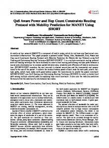
Sample Layout decomposition result by (a) [9]
and (b) our approach.
checking. It is worth mentioning that the benchmarks are quite dense and some areas contain congested pins which are difficult for double patterning technology. Table 3 also shows that unresolvable conflicts exist in both of our result and wirelength-driven result, which may be fixed by postrouting techniques. Our approach outperforms wirelengthdriven routing with fewer conflicts. The number of vias is increased by 32% because we utilize layer assignment to prevent conflicts and to improve the pattern quality. Fig. 11 shows a 1D layout generated by SADP-friendly layout decomposition [9] and our approach. Our result tends to generate more mandrel patterns and reduces the number of non-spacer-protected trim patterns, which implies our result obtains better pattern quality according to the proposed routing guidelines. Overall, our approach consistently achieves SADP-compliant results with negligible wirelength overhead. We provide more flexibility on layout decomposition by taking layer assignment into consideration. In addition, our prescribed lay-
31
7. ACKNOWLEDGEMENTS This work is supported in part by NSF, Oracle, and NSFC.
8. REFERENCES [1] Jo Finders, Micrea Dusa, and Stephen Hsu. Double patterning lithography: The bridge between low k1 ArF and EUV. Microlithography World, February 2008. [2] George E. Bailey, Alexander Tritchkov, Jea-Woo Park, Le Hong, Vincent Wiaux, Eric Hendrickx, Staf Verhaegen, Peng Xie, and Janko Versluijs. Double pattern EDA solutions for 32nm HP and beyond. In Proc. of SPIE, volume 6521, 2007. [3] A. B Kahng, C.-H. Park, X. Xu, and Hailong Yao. Layout decomposition for double patterning lithography. In Proc. Int. Conf. on Computer Aided Design, November 2008. [4] Jae-Seok Yang, K. Lu, Minsik Cho, Kun Yuan, and D. Z. Pan. A new graph-theoretic, multi-objective layout decomposition framework for double patterning lithography. In Proc. Asia and South Pacific Design Automation Conf., January 2010. [5] Szu-Yu Chen and Yao-Wen Chang. Native-conflict-aware wire perturbation for double patterning technology. In Proc. Int. Conf. on Computer Aided Design, November 2010.
[6] Kun Yuan and D. Z. Pan. WISDOM: wire spreading enhanced decomposition of masks in double patterning lithography. In Proc. Int. Conf. on Computer Aided Design, November 2010. [7] Martin Drapeau, Vincent Wiaux, Eric Hendrickx, Staf Verhaegen, and Takahiro Machida. Double patterning design split implementation and validation for the 32nm node. In Proc. of SPIE, volume 6521, 2007. [8] Yuansheng Ma, Jason Sweis, Chris Bencher, Huixiong Dai, Yongmei Chen, Jason P. Cain, Yunfei Deng, Jongwook Kye, and Harry J. Levinson. Decomposition strategies for self-aligned double patterning. In Proc. of SPIE, 2010. [9] Yongchan Ban, K. Lucas, and D. Z. Pan. Flexible 2D layout decomposition framework for spacer-type double pattering lithography. In Proc. Design Automation Conf., June 2011. [10] Michael C. Smayling, Christopher Bencher, Hao D. Chen, Huixiong Dai, and Michael P. Duane. APF pitch-halving for 22nm logic cells using gridded design rules. In Proc. of SPIE, volume 6925, 2008. [11] Yayi Wei and Robert L. Brainard. Advanced processes for 193-nm immersion lithography. In Proc. of SPIE, February 2009. [12] Yue Xu and C. Chu. GREMA: graph reduction based efficient mask assignment for double patterning technology. In Proc. Int. Conf. on Computer Aided Design, November 2009.
[13] Hongbo Zhang, Yuelin Du, Martin D. F. Wong, and Rasit Topaloglu. Self-aligned double patterning decomposition for overlay minimization and hot spot detection. In Proc. Design Automation Conf., 2011. [14] Minsik Cho, Yongchan Ban, and D. Z. Pan. Double patterning technology friendly detailed routing. In Proc. Int. Conf. on Computer Aided Design, November 2008. [15] Kun Yuan, K. Lu, and D. Z. Pan. Double patterning lithography friendly detailed routing with redundant via consideration. In Proc. Design Automation Conf., July 2009. [16] Minoo Mirsaeedi, J. Andres Torres, and Mohab Anis. Self-aligned double-patterning (SADP) friendly detailed routing. In Proc. of SPIE, 2011. [17] Kevin Lucas, Christopher Cork, Alexander Miloslavsky, Gerard Luk-Pat, Levi Barnes, John Hapli, John Lewellen, Greg Rollins, Vincent Wiaux, and Staf Verhaegen. Double-patterning interactions with wafer processing, optical proximity correction, and physical design flows. Journal of Micro/Nanolithography, MEMS and MOEMS, 8, 2009. [18] A. Guttma. R-Trees: a dynamic index structure for spatial searching. In Proc. SIGMOD Int. Conf. on Management of data, 1984.
32