Aug 11, 2003 - the docking or grasp point is on the V-bar or R-bar. The target satellite might be spinning or even tumbling, and the rotation axis might be in an ...
AIAA 2003-5745
AIAA Guidance, Navigation, and Control Conference and Exhibit 11-14 August 2003, Austin, Texas
FLY-BY APPROACH AND GUIDANCE FOR UNCONTROLLED ROTATING SATELITE CAPTURE Shuichi Matsumoto,* Steven Dubowsky,** Stephen Jacobsen** and Yoshiaki Ohkami*
* National Space Development Agency of Japan (NASDA), Tsukuba, Ibaraki, Japan ** Massachusetts Institute of Technology (MIT), Cambridge, MA, USA ABSTRACT Existing orbital transfer vehicles such as US Space Shuttles, Progress and Japanese H-IIA Transfer Vehicle (HTV) use a straight path approach to the International Space Station (ISS). The straight path approach has many advantages and is suitable for stable targets such as ISS and three-axis attitude-controlled satellites. However, for satellite capture missions, we cannot assume that the target satellite is in a stable attitude or that the docking or grasp point is on the straight path. We therefore developed a fly-by approach and capture method for uncontrolled satellite capture, in which a space robot approaches a target on a non-collision path subject to orbital mechanics and executes capturing task using its manipulator if everything goes well. This approach method can be used for arbitrary target positions and velocities in three-dimensional space. By choosing an appropriate initial position and velocity to utilize orbital mechanics, a space robot can approach a target position and velocity without any active trajectory control. This paper focuses on a fly-by approach method for uncontrolled rotating satellite capture considering collision avoidance between space robots and the target satellite, discusses the relative motion behavior during the fly-by approach, and develops planning and guidance algorithms for the fly-by approach.
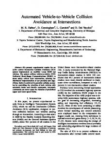
1. Introduction The International Space Station (ISS) is being constructed on orbit and US Space Shuttles have been transporting astronauts and ISS sub-modules. The European Automated Transfer Vehicle (ATV) and Japanese H-IIA Transfer Vehicle (HTV) are now being developed to supply logistics to the ISS.1,2,3 In the final approach, all these vehicles approach ISS from the orbital radius direction (R-bar, Fig.1) or orbital velocity direction (V-bar) aiming to static docking ports or berthing areas.4 Engineering Test Satellite VII (ETSVII) successfully demonstrated autonomous rendezvous and docking for a stable target also using a V-bar approach.5 It also demonstrated stable satellite capture by a tele-operated manipulator.6 Although these vehicles use orbital mechanics for orbital transfer phase and terminal approach phase, for final approach phase they approach a target along a straight path, either V-bar or R-bar, compensating for the effects of orbital mechanics. This straight path approach is suitable for stable targets
V- bar Approach Travelling Direction
Target
Earth
Fly- by Approach
R- bar Approach
Radius Direction
Fig. 1 V-bar, R-bar and Fly-by Approach for several reasons. First, the markers on the target are visible from sensors on the approaching vehicles at any time during the final approach. The lighting condition for sensor measurement is also almost the same, which is very important for accurate navigation. Second, the straight path on the V-bar or R-bar is a non-collision path until just before docking because if the approaching vehicle discontinues the path-keeping maneuver, the approach becomes curved path so that the vehicle can avoid colliding with the target. Third, the direction of the thruster firing to compensate for orbital mechanics effects is perpendicular to the approaching direction if the approach path is on the V-bar or R-bar, so the vehicle causes no plume impingement on the target satellite. Thus, the V-bar approach or R-bar approach has many advantages and has been actually used to approach stable targets such as ISS or three-axis attitude controlled satellites. However, for satellite capture missions, we cannot assume that the target satellite is in stable attitude or that the docking or grasp point is on the V-bar or R-bar. The target satellite might be spinning or even tumbling, and the rotation axis might be in an arbitrary direction. The Space Shuttle has a limited ability to approach from any direction with astronauts in the guidance loop. The Space Shuttle uses a glide-slope approach method in which the Space Shuttle maintains a straight path from initial location to target deceasing its velocity by thruster firing.7 Although one way to avoid plume impingement is to use canted thrusters for target direction like the Space Shuttle, the plume might still impinge on a target if the target is relatively larger than the approaching vehicle. Furthermore, a target satellite is requested to fold or detach its solar panel before a Space Shuttle
- 1American Institute of Aeronautics and Astronautics Copyright © 2003 by Authors. Published by the American Institute of Aeronautics and Astronautics, Inc., with permission.
approach. Thus the glide-slope approach cannot be used for an uncontrolled satellite capture mission. An optimization based trajectory planning method may be used for an uncontrolled satellite capture. However it requires a complicated position and attitude control system. 14,15 We thus developed a fly-by approach and capture method for uncontrolled satellite capture, in which a space robot approaches a target on a non-collision path subject to orbital mechanics and executes capturing task using its manipulator if everything goes well. This method can be applied to arbitrary target positions and velocities in three-dimensional space. By choosing an appropriate initial position and velocity to utilize orbital mechanics, a space robot can approach a target position at an appropriate velocity without any active trajectory control. For the capture manipulation, we can use control methods for a free-floating space robot.8,9 This paper focuses on a fly-by approach method for uncontrolled rotating satellite capture considering collision avoidance between space robots and the target satellite, discusses the relative motion behavior during the final approach, and develops planning and guidance algorithms for the fly-by approach.
capturing period is relatively short (a few seconds) compared with the period of rotation (20-3600 seconds), so we can approximate the slow rotating motion by pure rotational motion for the fly-by capture. To reduce transitional force and torque during the capture, the approaching velocity at the closest point of fly-by is matched with the velocity of grasp point on the target satellite at grasp time. In this method, if there is a system failure or unexpectedly large errors, the space robot avoids executing capture manipulation and can escape from the target satellite without a collision avoidance maneuver. For the category IV satellite, we have been examining the synchronized spinning approach method, in which a space robot approaches a spinning satellite and synchronizes its attitude or synchronizes manipulator motion to the satellite spinning motion. However, this approach might violate the non-collision approach condition and is beyond the scope of this paper.
2.2 Basic Strategy for Fly-by Satellite Capture
The fly-by satellite capture consists of the following seven phases. (1) Target motion estimation (2) Task planning for capture 2. Basic Strategy for Fly-by Satellite Capture (3) Proximity approach (4) Capturing manipulation (5) Grasp control 2.1 Categorization of Satellite Capture Strategies (6) Relative motion damping The target satellite motions to be captured are roughly (7) Collision avoidance categorized as follows.10 Category I Satellite with three-axis attitude control Category II Satellite with gravity gradient stabilization Category III Slowly tumbling satellite Category IV Spinning satellite 100
Attitude Rate (deg/sec)
18 10
(IV)Spinning Satellite (III)Slowly Tumbling Satellite
1 0.1
(I)Satellite with three axis attitude control
(II)Satellite with gravity gradient (I) stabilization 0.1
1
10
90 180 100
Attitude Error (deg)
Fig. 2 Category of Satellite Motion Figure 2 illustrates the strategy classification based on the attitude error and attitude rate. Existing remote manipulators can capture satellites in category I. For categories II and III, we propose the fly-by approach and capture method, in which a space robot approaches on a non-collision path and executes a capturing task by using its manipulator at the closest point of the fly-by non-collision path. For categories II and III, the
At about 30 to 100m from a target satellite, a space robot observes the target satellite motion and estimates its dynamic states such as quaternion and angular velocity vector (Target motion estimation). Using the estimated motion parameters, the space robot makes a capture plan considering satellite motion, lighting conditions, collision avoidance, error compensation ability and so on (Task planning for capture). The robot approaches the target on a non-collision path using orbital mechanics (Proximity approach) and uses its manipulator to compensate for position and velocity errors during the proximity approach phase and to match the relative position and velocity between its endeffector and the grasp point on the target satellite (Capturing manipulation). During the mechanical grasp, the manipulator keeps the relative position and velocity and manages force and torque caused by mechanical contact between the end-effecto and the grasp point (Grasp control). After the grasp, the space robot damps out the relative motion between the robot and the target satellite (Relative motion damping). If there is a system failure or unexpected large error during the approach, the space robot avoids executing the capturing manipulation and escapes from the target satellite using orbital mechanics (Collision Avoidance)
- 2American Institute of Aeronautics and Astronautics
3. Relative Motion Behaviors during Approach 3.2 In-plane Relative Motion Behavior 3.1 Orbital Dynamics on Relative Motion This paper uses Hill’s coordinate system to express the relative motion of the space robot (Chaser) with respect to the target satellite (Target). Hill’s coordinate system is a rotating coordinate system with the orbital rate of the target. The origin is at the target center of mass. The Z axis is toword the center of the Earth, and the X axis is the tangential Direction of the target. Figure 3 shows the definition of Hill’s coordinate system used in this paper. Chaser
Y axis
ρ =(x,y,z)
(Orbit Anti-normal
Target
X axis
(Tangential Direction)
r
Ω
Z axis
(Radial Direction)
rt
Orbital Rate
•Origin: Target •X Axis: Orthogonal to Y and Z axis Center of the Earth •Y Axis: Orbit Anti-Normal Direction •Z Axis: Direction to the center of the Earth •Position of Chaser: ρ=r-rt=[x, y, z]T •Rotation of the Coordinate system: Ω=[0 -Ωt 0]T Ωt : Orbital rate of Target
Fig.3 Hill’s Coordinate system & × ρ + Ω × (Ω × ρ) = g + A (1) &r& = &r&t + ρ && + 2(Ω × ρ& ) + Ω (A) (B) (C) (D) (E) (A) Coriolis Force (B) Eular’s Acceleration (C) Centrifugal Force
(D) Gravity Force (E) External Acceleration
The equation of motion of a space robot in Hill’s coordinate system is described below. Since we are discussing a proximity approach, the distance between the Chaser and Target is much less than the orbital radius. Furthermore, most satellites are in circular orbits, so we can assume that the Target is in a circular orbit. Using these assumptions, we obtain a linearized Hill’s equation as in Equation (2).11,12,13 &x& = 2 ⋅ Ωt ⋅ z& + Ax (2a)
&y& = −Ωt 2 ⋅ y + Ay
(2b)
&z& = − 2 ⋅ Ωt ⋅ x& + 3 ⋅ Ω t 2 ⋅ z + Az
(2c)
This section examines the behavior of in-plane relative motion without external accelerations. Equation (2) can be described in a vector form as Equation (3). Since the orbital rate, Ωt , is much smaller than the relative velocity, ρ& , the colioris force, the first term of the right-hand side of Equation (3), dominates the Chaser’s translational motion in the proximity zone. 0
0 0 − 1 0 0 0 3
&& = − 2 ⋅ Ω × ρ& + Ω t 2 ⋅0 ρ
⋅ρ
Since the orbital angular velocity vector, Ω, is on the −y-axis of Hill’s coordinate system, the colioris force effects only in-plane relative motion (x and z coordinates), and free-floating approach path is curved in the right-handed screw direction with respect to +yaxis. For satellite capture problem, since a grasp point on a target satellite is rotating around the angular velocity vector of the target satellite, the relationship between the grasp point and approach path that is projected onto the x-z plane is illustrated as Fig. 4. Even though we need to examine a safe approach to a target satellite in three dimensions, we can intuitively feel that this physical nature could be useful for a safe approach if we choose appropriate conditions. For example, if we choose the targeted grasp point at point G on Fig. 4, which also determines the grasp time, the Chaser can approach from and escape to an area farther from the target satellite using approach path G on Fig. 4. The details of planning and real-time guidance of the safe approach using orbital mechanics are discussed in a later section. To see this in-plane relative motion behavior for the fly-by approach, an in-plane relative motion simulation was performed. In the simulation it was assumed that the target satellite was spinning along the z-axis of Hill’s coordinates. The targeted position and velocity of the proximity approach, XT and VT, are as depicted in Fig. 5. By choosing appropriate target conditions, we can establish a non-collision path in which the Chaser Approach Paths Approach Path G Grasp Point Track
y Velocity
Spin
x Point G
where Ax, Ay, Az are external accelerations If there is no external accelerations, Ax=Ay=Az=0, relative motion can be divided into in-plane motion (x and z coordinates) and out-of-plane motion (y coordinates).
(3)
z
Fig.5 Grasp point velocity and approaching path
- 3American Institute of Aeronautics and Astronautics
approaches from safer zone and also escapes to safer zone as shown in Fig. 6. Figure 7 shows the relative position between the approach trajectory and the region where a collision with the target satellite body or solar panels could occur. The collision region is represented by the cylinder in the figure. We can confirm the trajectory is a non-collision path from Fig. 8. yh
zh
Spin Axis
xh
yh
zh xh Xg
zh yh
xh
Xg Xt
Vg Vt
Xt Xg:Position of Grasping Point Vg:Velocity of Grasping Point Xt:Target Position of Approach Xt:Target Velocity of Approach
- Target Spin Axis: +z Axis of Hill’s Coordinates - XT=[0 -1.5 -1.5], VT=[vt 0 0] ( vt = 0.05m/s, 0.1m/s, 0.2m/s, 0.35m/s, 0.5m/s, 1m/s, 2m/s )
Fig. 5 Targeted position and velocity (In-plane motion) spin
3.3 Out-of-plane Relative Motion Behavior This section examines the behavior of out-of-plane relative motion without external accelerations. From Equation (2b), we can see the motion in the y-direction is simple harmonic motion with a period of one orbital revolution, T1rev =
2π . If there is no in-plane motion, Ωt
which occurs when the target velocity of the proximity approach has only a y component and the target position has no x and z components, the relative motion is simple harmonic motion parallel to the y-axis. This motion would be hazardous because if the Chaser loses its flight control system for some reason during the approach, the vehicle approaches closer to a target satellite every orbital period by nature of orbital mechanics. Thus, we should avoid using this purely out-of-plane relative motion. If an angular velocity vector of the target satellite is along the y-axis of Hill’s coordinates, the case is a kind of singular point for the fly-by approach method. In this case, the approach path curves in the plane almost perpendicular to spinning axis, which means that there is no advantage for safety to use orbital mechanics for approach. To see this relative motion behavior, a relative motion simulation was performed with the following conditions: - Target spin axis: +y-axis of Hill’s coordinates - Xt=[-1.5 -1.5 0] - Vt=[0 0 vt]( vt = 0.05m/s, 0.1m/s, 0.2m/s, 0.35m/s, 0.5m/s, 1m/s, 2m/s )
Fig.6 In-plane relative motion simulation result
Fig.8 Relative position between approach trajectory and collision region (Out-of-plane relative motion)
Fig.7 Relative position between approach trajectory and collision region (In-plane relative motion)
Figure 8 shows the simulation results. From the figure, we can see that the approach path curves in the plane almost perpendicular to the y-axis, which is the spin axis. Even though the approach path is a non-collision path, there is no advantage for safety to use the curved
- 4American Institute of Aeronautics and Astronautics
Gas Jet Thruster Restriction Area (Sphere)
Start Point of Approach
Spin Axis
Position and Velocity of Grasp Point
Initial Maneuver (CW guidance)
Target of Escape Trajcetory using orbital Mechanics Fly-by Approach
Capture Manipulation
Terminal Approach Phase Mid-Coarse Maneuvers (CW guidance)
Trajctory Adjusting Maneuvers (Reference Guidance)
Approach Trajcetory using orbital Mechanics
Trajectory Adjusting Phase
Fly- by Escape Phase
Fly- by Approach Phase
Fig. 9 Fly-by approach to target satellite approach in this case. We can also see that the approach path and escape path are slightly closer to the collision region than the target position of the approach. This is due to the out-of-plane relative motion. Since the amount of this change is small, we can choose noncollision path considering appropriate offset and length of solar panel as shown in Fig. 8. However for the sake of safety, we should avoid this special situation by choosing an appropriate grasp time and select the target position and velocity such that the Chaser makes maximum use of in-plane convex approach motion.
4. Fly-by Approach Planning and Guidance 4.1 Outline of Fly-by Approach The fly-by approach consists of the following four phases. Figure 9 illustrates the sequence of the fly-by approach. (1) Terminal approach phase (2) Trajectory adjusting phase (3) Fly-by approach phase (4) Fly-by escape phase A space robot can start the transfer maneuver phase from an arbitrary position and executes transfer maneuvers to match its position and velocity with the initial conditions for the fly-by approach at the appropriate time (Terminal approach phase). The CW guidance law can be used for the transfer maneuvers. During this phase, the robot’s attitude and manipulator configuration should be prepared for the capture manipulation. After injection for the fly-by approach trajectory, the space robot executes the trajectory
adjusting maneuvers to compensate for position, velocity and timing errors due to the transfer maneuver and motion estimation (Trajectory adjusting phase). Reference trajectory guidance may be suitable for these maneuvers. While in close proximity to the satellite, the space robot should restrict thruster firing to avoid plum impingement on the satellite and panels. For this reason, in the fly-by approach, space robot approaches the target on a passive trajectory resulting from orbital mechanics (Fly-by approach phase). To reduce interactive forces and torques during capture, the approach velocity at the closest point of fly-by is matched with the velocity of grasp point on the target satellite at grasp time. If there are no system failure and the capturing conditions are satisfied, the space robot executes capture manipulation, absorbs the relative position and timing error, and grasps a secure point on the target satellite. If a system failure or unexpectedly large error occurs, the space robot does not execute the capturing manipulation and escapes from the target satellite without any additional collision avoidance maneuver (Fly-by escape phase).
4.2 Motion Dynamic Equations for Fly-by Approach Since we assume that the target satellite is an uncontrolled rotating target, the space robot only has partial visibility during approach. In addition, the spinning axis of the target satellite is in arbitrary direction and may change its direction gradually due to its rigid body motion and external forces such as gravity gradient force. Thus, this approach is based on the physical dynamic equations of the target satellite attitude motion and orbital mechanics. The motion dynamic equations are described below.
- 5American Institute of Aeronautics and Astronautics
(1) Attitude Motion Dynamic Equation • 1 q TI ⋅ Q T ⋅ ωTB (4) 0 = 2 + −1 B ωB T − I −1 ⋅ ω B × (I ⋅ ω B ) I T ⋅ M T T T T T where ωTB : Angular velocity vector of a target satellite with respect to body coordinate system qTI : Quaternion of a target satellite attitude with respect to inertial coordinate system
(
)
qTI =[ q0 q1 q2 q3]T, Q T
− q1 q0 = q3 − q 2
− q2 − q3 q0 q1
− q3 q2 − q1 q 0
IT: Inertia matrix MTB : External torque with respect to body coordinate system
(2)Transnational Motion Dynamic Equation
0 x = µg vI − T xI 3 T • I T
where
1 xI T 0 ⋅ vI T
(5)
xTI : Target satellite position with respect to inertial coordinate system vTI : Target satellite velocity with respect to inertial coordinate system µg : Gravitational constant
The position and velocity of the grasp point on the target in Hill’s coordinate system can also be obtained as below. H I H I B xH g = C I C B x g + C I xT
(8)
H I B H I I B B vH g = C I C B ( ωT × x g )+ C I ( Ω ×( C B x g ))
(9)
where x Bg : Grasp point position with respect to body coordinate system
4.3 Target position and velocity for fly-by approach This section discusses how to determine the target position and velocity of the fly-by approach. We assume that the angular velocity of the target satellite is much larger than the orbital angular velocity and that the angular velocity vector can be approximated as a single vector, which means the angular velocity vector can be approximated as fixed during one revolution of the target motion. As discussed in chapter 3, the fly-by approach avoids the out-of-plane motion and uses the in-plane motion so as to maximize the curvature of safe convex approach. Since the grasp point on the target satellite is rotating around an angular velocity vector, we can choose the grasp time when the grasp point has no ycomponent of the velocity. To clarify the relationships between angular velocity vector, grasp point and axes of Hill’s coordinate system, the representation shown in Fig. 10 is introduced. Using this representation, the angular velocity vector, and grasp point position are described in Equations (10), (11) and (12).
If target motion states xTI , vTI , qTI , and ωTB are estimated at some time, we can predict the target motion H for the future using Equations (4) and (5). Although an ey accurate and efficient motion estimation method is ω : Angular velocity vector of the target required for this approach method, in this paper we XT: Grasp point position g assume that the target motion is estimated with a small e , e , e : Unit vectors of Hill’s x y z estimation error. coordinate system
Using the estimated target motion, xTI , vTI , qTI , ωTB , Upper left suffix ‘H’ means that a vector is represented in Hill’s coordinate system the angular velocity vector and angular acceleration vector of the target satellite in Hill’s coordinate system can be obtained as below. I B ωTH = C H I ⋅ C B ⋅ ωT
(6)
I &B H I I B & TH = C H ω I ⋅ CB ⋅ ω T + C I (Ω × C B ⋅ ωT )
(7)
where CIB : Coordinate transfer matrix from body coordinates to inertial coordinates
CH I : Coordinate transfer matrix from inertial coordinates to Hill’s coordinates ΩI =
xTI
×
xTI
vTI 2
: Orbital angular velocity vector
H
ω
ey
ωT
ω
H
xg
φω
ex
ξω
ψω H
θω
ex
H
ez
Fig. 10 Relationships between angular velocity vector, grasp point and Hill’s coordinate system
cosψ ⋅ sin θω cosψ ⋅ cosθ ω ω
ω ωTH = ωTH sinψ ω
- 6American Institute of Aeronautics and Astronautics
(10)
0 Ω H = - Ω t ⋅ e Hy = − Ω t 0
For φω= ± π , the condition for a convex approach to the 2 target becomes
(11)
cosψ ω ⋅ sin θω ⋅cosξω⋅ sinψ ω cosψ ⋅ cosθ ω ω
H xH g = xg cosθ ω ⋅ cosφω − sin θ ω sinψ ω ⋅ sin φω H + x g ⋅sinξω⋅ cosψ ω ⋅ sin φω − sin θ ⋅ cosφ − cosθ sinψ ⋅ sin φ ω ω ω ω ω
(
(ωTH )T ⋅ x Hg ωTH T && H ⋅ H ) ⋅ Xg = ωTH ωT 2
(12)
± 2Ωt ωTH ⋅ x Hg ⋅sinξω⋅cosξω⋅cosψω 2
2
−Ωt x Hg ⋅cosξω⋅sin(ψω±ξω)⋅cosψω 2
The y-component of v H g should be zero to maximize inplane convex approach motion, which can be described as H H T H T ( eH y ) ⋅ v g = ( e y ) ⋅( ωT × x g ) = 0 H
(13)
(16)
2
+ 3Ωt x Hg ⋅cosξω⋅cos(ψω±ξω)⋅cosψω⋅cos2θω Since the orbital rate, Ωt, is usually much smaller than the angular velocity of the target attitude motion, Equation (16) can be approximated as Equation (17).
(ωTH )T ⋅ x Hg ωTH T && H ( ⋅ H ) ⋅ Xg ≅ Substituting Equations (10) and (12) into Equation (13), ωTH ωT we get the following simple equation.
H T ( eH y ) ⋅( ωT × x g ) = − ωT × x g cosψω⋅cosφω=0 H
H
H
(14)
Thus, the conditions that satisfied Equation (14) are as follows. (a) If ψω=± π then φω is arbitrary. 2
angle between ωT and x g is more than 90 degrees, φω H
The condition for the safe convex approach to a target is given by (15)
mechanics at
,
&& H X g
=
2Ω t ⋅ z& gH − Ω 2 ⋅ yH t g − 2Ω t ⋅ x& gH + 3 ⋅ Ω t 2 ⋅ z gH
H
must be − π to satisfy the safe convex approach 2 condition. Using this result, we can determine the target position H
H
and velocity of the grasp point, x gt , v gt , to satisfy the safe convex approach as follows:
&& H is the acceleration vector by orbital where X g xH g
Since ξω ranges from 0 to +180 degrees, sinξ is zero or positive, and since ψω ranges from –90 to +90 degrees, cosψω is also zero or positive. Thus, if the angle between 2 satisfy the safe convex approach condition, and if the
2
(ωTH )T ⋅ x Hg ωTH T && H ⋅ H ) ⋅ X g >0 ( ωTH ωT
(17)
ωTH and x Hg is less than 90 degrees, φω must be + π to
( for convenience, we chose φω= ± π in this case)
(b) If ψω ≠ ± π then φω= ± π . 2 2
2
± 2Ωt ωTH ⋅ x Hg ⋅sinξω⋅cosξω⋅cosψω
(1)If angle between ωT and x g is less than 90 degrees: H
The right vector of the inner product of Equation (15) is the projection of x H g onto the angular velocity vector. If
x Hgt = x Bg
H
sin θ ω ⋅ cos(ψ ω + ξ ω ) sin(ψ ω + ξ ω ) cosθ ⋅ cos(ψ + ξ ) ω ω ω
− cosθ ω 0 sin θ ω
v Hgt = ωTH × x Hgt = ωTB ⋅ x Bg ⋅sinξω⋅
&& H is the inner product of this projected vector and X g positive, the orbital mechanics act on the Chaser approach trajectory such that the approach trajectory is convex to the target satellite at the closest point of the fly-by approach.
(18a)
(19a)
(2)If angle between ωT and x g is more than 90 degrees: H
x Hgt = x Bg
H
sin θ ω ⋅ cos(ψ ω − ξ ω ) sin(ψ ω − ξ ω ) cosθ ⋅ cos(ψ − ξ ) ω ω ω
- 7American Institute of Aeronautics and Astronautics
(18b)
cos θ ω − sin θ ω
v Hgt = ωTH × x Hgt = ωTB ⋅ x Bg ⋅sinξω⋅ 0
(19b)
Offsets from the grasp point for target position and velocity of approach trajectory should be set considering capturing manipulation capability and position error due to the error at the final maneuver point. The easiest way to determine the target position and velocity of an approaching point is as follows: δr )⋅ x Hgt XH (20) Ft =(1+ x Bg
H H VFt =(1+ δr )⋅ v gt
(21)
x Bg
where X HFt : Position of fly-by approach target point H : Velocity of fly-by approach target point VFt
δr : Offset from the grappling point
4.4 Task planning for Fly-by Approach Using the physical dynamic equations described in section 4.2 and the target conditions described in section 4.3, the Chaser performs task planning for the fly-by approach to determine task parameters such as grasp time, grasp point and target points of the approach. While a grasp point is uniquely determined in each rotation, there are multiple candidates for same grasp conditions considering approach start time over a period of rotations. Since the target satellite attitude motion is independent of its orbital motion, a suitable condition for the fly-by approach can be selected by choosing appropriate approach start time considering following conditions. (a) Rapid motions of a target satellite during the rotating axis change should be avoided. H H I B (Example: ωT = CI CB ωT