cation system von Henke 1988]. A major objective of the ... Rushby and von ...... Moser 1987] Louise Moser, Michael Melliar-Smith, ... Rushby1989] John Rushby and Friedrich von. Henke. ... Schubert 1991] Thomas Schubert and Karl Levitt.
Formal Techniques for Synchronized Fault-Tolerant Systems1 Ricky W. Butler NASA Langley Research Center Hampton, VA 23665-5225 USA
Ben L. Di Vito V��GYAN, Inc. 30 Research Drive Hampton, VA 23666-1325 USA Abstract
The major goal of this work is to produce a veri ed real-time computing platform, both hardware and operating system software, useful for a wide variety of control-system applications. Toward this goal, the operating system provides a user interface that \hides" the implementation details of the system such as the redundant processors, voting, clock synchronization, etc. We adopt a very abstract model of real-time computation, introduce three levels of decomposition of the model towards a physical realization, and rigorously prove that the decomposition correctly implements the model. Speci cations and proofs have been mechanized using the Ehdm veri cation system [von Henke 1988]. A major objective of the RCP design is to enable the system to recover from the e�ects of transient faults. More than their analog predecessors, digital
ight control systems are vulnerable to external phenomena that can temporarily a�ect the system without permanently damaging the physical hardware. External phenomena such as electromagnetic interference (EMI) can ip the bits in a processor's memory or temporarily a�ect an ALU. EMI can come from many sources such as cosmic radiation, lightning or High Intensity Radiated Fields (HIRF). RCP is designed to automatically purge the e�ects of transients periodically, provided the transient is not massive, that is, simultaneously a�ecting a majority of the redundant processors in the system. Of course, there is no hope of recovery if the system designed to overcome transient faults contains a design aw. Consequently, emphasis has been placed on techniques that mathematically show when the desired recovery properties are obtained.
We present the formal veri cation of synchronizing aspects of the Reliable Computing Platform (RCP), a fault-tolerant computing system for digital ight control applications. The RCP uses NMR-style redundancy to mask faults and internal majority voting to purge the e�ects of transient faults. The system design has been formally speci ed and veri ed using the Ehdm veri cation system. Our formalization is based on an extended state machine model incorporating snapshots of local processors' clocks.
Key Words { Clock synchronization, correctness proofs, fault tolerance, formal methods, majority voting, modular redundancy, theorem proving, transient fault recovery.
1 Introduction NASA is engaged in a major research e�ort towards the development of a practical validation and veri cation methodology for digital y-by-wire control systems. Researchers at NASA Langley Research Center (LaRC) are exploring formal veri cation as a candidate technology for the elimination of design errors in such systems. In previous reports [Di Vito 1990, Di Vito 1992, Butler 1991], we put forward a high level architecture for a reliable computing platform (RCP) based on fault-tolerant computing principles. Central to this work is the use of formal methods for the veri cation of a fault-tolerant operating system that schedules and executes the application tasks of a digital ight control system. Phase 1 of this e�ort established results about the high level design of RCP. This paper discusses our Phase 2 results, which carry the design, speci cation, and veri cation of RCP to lower levels of abstraction. Complete details of the Phase 2 work are available in technical report form [Butler 1992].
1.1 Design of RCP
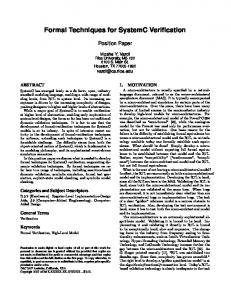
We propose a well-de ned operating system that provides the applications software developer a reliable mechanism for dispatching periodic tasks on a faulttolerant computing base that appears to him as a sinThird IFIP International Working Conference on Depend- gle ultra-reliable processor. A four-level hierarchical able Computing for Critical Applications. Mondello, Sicily, decomposition of the reliable computing platform is Italy. September 14{16, 1992. shown in gure 1. 1
85
Uniprocessor System Model (US)
Sensors
j
?
Fault-tolerant Replicated Synchronous Model (RS)
j
Interactive Consistency Distribution Network
Fault-tolerant Distributed Synchronous Model (DS)
j
Fault-tolerant Distributed Asynchronous Model (DA)
Processor Replicate 1
j
Hardware/Software Implementation
Figure 1: Hierarchical speci cation of RCP.
Interprocessor Communication Link
...
Interprocessor Communication Link
Processor Replicate R
?. . . ?
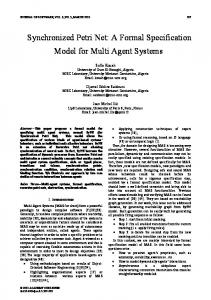
The top level of the hierarchy describes the operating system as a function that sequentially invokes application tasks. This view of the operating system will be referred to as the uniprocessor model, which forms the top-level requirement for the RCP. Fault tolerance is achieved by voting the results computed by the replicated processors operating on identical inputs. Interactive consistency checks on sensor inputs and voting of actuator outputs requires synchronization of the replicated processors. The second level in the hierarchy describes the operating system as a synchronous system where each replicated processor executes the same application tasks. The existence of a global time base, an interactive consistency mechanism and a reliable voting mechanism are assumed at this level. Although not anticipated during the Phase 1 effort, another layer of re nement was inserted before the introduction of asynchrony. Level 3 of the hierarchy breaks a frame into four sequential phases. This allows a more explicit modeling of interprocessor communication and the time phasing of computation, communication, and voting. The use of this intermediate model avoids introducing these issues along with those of real time, thus preventing an overload of details in the proof process. At the fourth level, the assumptions of the synchronous model must be discharged. Rushby and von Henke [Rushby 1989] report on the formal veri cation of Lamport and Melliar-Smith's [Lamport 1985] interactive-convergence clock synchronization algorithm. This algorithm can serve as a foundation for the implementation of the replicated system as a collection of asynchronously operating processors. Dedicated hardware implementations of the clock synchronization function are a long-term goal. Figure 2 depicts the generic hardware architecture assumed for implementing the replicated sys-
Actuators
Figure 2: Generic hardware architecture. tem. Single-source sensor inputs are distributed by special purpose hardware executing a Byzantine agreement algorithm. Replicated actuator outputs are all delivered in parallel to the actuators, where force-sum voting occurs. Interprocessor communication links allow replicated processors to exchange and vote on the results of task computations. As previously suggested, clock synchronization hardware will be added to the architecture as well.
1.2 Previous E�orts Many techniques for implementing fault-tolerance through redundancy have been developed over the past decade, e.g. SIFT [Goldberg 1984], FTMP [Hopkins 1978], FTP [Lala 1986], MAFT [Walter 1985], and MARS [Kopetz 1989]. An often overlooked but signi cant factor in the development process is the approach to system veri cation. In SIFT and MAFT, serious consideration was given to the need to mathematically reason about the system. In FTMP and FTP, the veri cation concept was almost exclusively testing. Among previous e�orts, only the SIFT project attempted to use formal methods [Moser 1987]. Although the SIFT operating system was never completely veri ed [NASA 1983], the concept of Byzantine Generals algorithms was developed [Lamport 1982] as was the rst fault-tolerant clock synchronization algorithm with a mathematical performance proof [Lamport 1985]. Other theoretical investigations have also addressed the problems of 86
replicated systems [Mancini 1988]. Some recent work has focused on problems related to the style of fault-tolerant computing adopted by RCP. Rushby has studied a fault masking and transient recovery model and created a formalization of it using Ehdm [Rushby 1991, Rushby 1992]. Rushby's model is more general than ours, but assumes a tighter degree of synchronization where voting takes place after every task execution. In addition, Shankar has undertaken the formalization of a general scheme for modeling fault-tolerant clock synchronization algorithms [Shankar 1991, Shankar 1992]. Several e�orts in hardware veri cation are likewise relevant. Bevier and Young have veri ed a circuit design for performing interactive consistency [Bevier 1991], while Srivas and Bickford have carried out a similar activity [Srivas 1991]. Schubert and Levitt have veri ed the design of processor support circuitry, namely a memory management unit [Schubert 1991].
architecture that is capable of masking the e�ects of faults, but makes no attempt to detect or diagnose those faults. Transient fault recovery is the result of an automatic, continuous voting process; no explicit invocation is involved.
2.1 RCP State Machines
The RCP speci cation consists of four separate models of the system: Uniprocessor System (US), Replicated Synchronous (RS), Distributed Synchronous (DS), Distributed Asynchronous (DA). Each of these speci cations is in some sense complete; however, they are written at di�erent levels of abstraction and describe the behavior of the system with di�erent degrees of detail. 1. Uniprocessor System layer (US). This constitutes the top-level speci cation of the functional system behavior de ned in terms of an idealized, fault-free computation mechanism. This speci cation is the correctness criterion to be met by all lower level designs. 2. Replicated Synchronous layer (RS). Processors are replicated and the state machine makes global transitions as if all processors were perfectly synchronized. Interprocessor communication is implicit at this layer. Fault tolerance is achieved using exact-match voting on the results computed by the replicated processors operating on identical inputs. 3. Distributed Synchronous layer (DS). Next, the interprocessor communication mechanism is modeled and transitions for the RS layer machine are broken into a series of subtransitions. Activity on the separate processors is still assumed to occur synchronously. Interprocessor communication is accomplished using a simple mailbox scheme. 4. Distributed Asynchronous layer (DA). Finally, the lowest layer relaxes the assumption of synchrony and allows each processor to run on its own independent clock. Clock time and real time are introduced into the modeling formalism. The DA machine requires an underlying clock synchronization mechanism.
2 Modeling Approach The speci cation of the Reliable Computing Platform (RCP) is based on state machine concepts. A system state models the memory contents of all processors as well as auxiliary variables such as the fault status of each processor. This latter type of information may not be observable by a running system, but provides a way to express precise speci cations. System behavior is described by specifying an initial state and the allowable transitions from one state to another. A transition speci cation must determine (or constrain) the allowable destination states in terms of the current state and current inputs. The intended interpretation is that each component of the state models the local state of one processor and its associated hardware. RCP speci cations are given in relational form. This enables one to leave unspeci ed the behavior of a faulty component. Consider the example below. Rtran : function[State; State ! bool] = ( � s; t : nonfaulty(s(i)) � t(i) = f (s(i))) In the relation Rtran, if component i of state s is nonfaulty, then component i of the next state t is constrained to equal f(s(i)). For other values of i, that is, when s(i) is faulty, the next state value t(i) is unspeci ed. Any behavior of the faulty component is acceptable in the speci cation de ned by Rtran. It is important to note that the modeling of component hardware faults is for speci cation purposes only and re ects no self-cognizance on the part of the running system. We assume a nonrecon gurable
Most of this paper will concentrate on the DA layer speci cation and its proof. The basic design strategy is to use a fault-tolerant clock synchronization algorithm as the foundation for the operating system, providing a global time base for the system. Although the synchronization is 87
not perfect, it is possible to develop a reliable communications scheme where the system clock skew is strictly bounded. For all working clocks p and q, the synchronization algorithm provides a bounded clock skew � between p and q, assuming that the number of faulty clocks, say m, does not exceed (nrep?1)=3, where nrep is the number of replicated processors. This property enables a simple communications protocol to be established whereby the receiver waits until maxb + � after a pre-determined broadcast time before reading a message (maxb is the maximum communication delay). Each processor in the system executes the same set of application tasks during every cycle of a continuously repeating task schedule. A schedule comprises a xed number of frames, each frame time units of time long. A frame is further decomposed into four phases: compute, broadcast, vote and sync. During the compute phase, all of the applications tasks scheduled for this frame are executed.2 The results of all tasks that are to be voted this frame are then loaded into the outgoing mailbox, initiating a broadcast send operation. During the next phase, the broadcast phase, the system merely waits a su�cient amount of time (maxb + �) to allow all of the messages to be delivered. During the vote phase, each processor retrieves all of the replicated data from each processor and performs a voting operation. Typically, majority voting is used for each of the selected state elements. The processor then replaces its local memory with the voted values. Finally, the clock synchronization algorithm is executed during the sync phase. Although conceptually this can be performed in either software or hardware, we intend to use a hardware implementation.
represent the time at which the last transition occurred (time current state was entered). If a state was entered by processor p at time T and is occupied for a duration D, the next transition occurs for p at time T + D and this clock value is recorded for p in the next state. A function cp (T) is assumed to map local clock values for processor p into real time. Notationally, s(i):lclock refers to the (logical) clock-time snapshot of processor i's clock in state s. Clocks may become skewed in real time. Consequently, the occurrence of corresponding events on di�erent processors may be skewed in real time. A state transition for the DA state machine corresponds to an aggregate transition in which each processor experiences the same event, such as completing one phase of a frame and beginning the next. Each processor may experience the event at di�erent real times and even di�erent clock times if duration values are not identical. Four classes of operations are distinguished: 1. L: Purely local processing that involves no broadcast communication or mailbox access. 2. B: Broadcast communication where a send is initiated when the state is entered and must be completed before the next transition. 3. R: Local processing that involves no send operations, but does include reading of mailbox values. 4. C: Clock synchronization operations that may cause the local clock to be adjusted and appear to be discontinuous. We make the simplifying assumption that the duration spent in each state, except those of type C, 2.2 Extended State Machine Model is nominally a xed amount of clock time. Allowances need to be made, however, for small variFormalizing the behavior of the Distributed Asyn- ations in the actual clock time used by real proceschronous layer requires a means of incorporating sors. Thus if � is the maximum rate of variation and time. We accomplish this by formulating an ex- DI ; DA are the intended and actual durations, then tended state machine model that includes a notion jDA ? DI j � �DI must hold. of local clock time for each processor. It also recognizes several types of transitions or operations that can be invoked by each processor. The type of oper- 2.3 The Proof Method ation dictates which special constraints are imposed The proof method is a variation of the classical alon state transitions for certain components. gebraic technique of showing that a homomorphism The time-extended state machine model allows for exists. Such a proof can be visualized as showing autonomous local clocks on each processor to be that a diagram \commutes" ( gure 3). Consider modeled using snapshots of clock time coinciding two adjacent levels of abstraction, called the top and with state transitions. Clock values within a state bottom levels for convenience. At the top level we Multi-rate scheduling is accomplished in RCP by having a have a current state, s , a destination state, t , and task execute every n frames, where n may be chosen di�erently a transition that relates the two. The properties of for each task. the transition are given as a mathematical relation, 0
2
88
0
Ntop (s ; t )
-
[von Henke 1988] is a mature tool, which has been under development by SRI International since 1983 6 6 and followed their earlier work on HDM. It comprises a highly integrated environment for formal system development. The speci cation language is based on map map a higher-order logic with features supporting module structure and parameterization. An operational subset of the language can be automatically translated to Ada. Nbottom (s; t) - t s Ehdm contains an automated theorem prover to support proving in the higher-order logic. Decision Figure 3: States, transitions, and mappings. procedures for several arithmetic domains are embedded in the system. Users invoke the prover by Ntop (s ; t ). Similarly, the bottom level consists of writing a proof directive in the speci cation lanstates, s and t, and a transition that relates the two, guage, stating explicit premises and any necessary Nbottom (s; t). The state values at the bottom level substitutions. are related to the state values at the top level by way of a mapping function, map. To establish that the bottom level implements the top level one must show that the diagram commutes (in a sense meant In this section we discuss the synchronization theory for relations instead of functions): upon which the DA speci cation depends. Although Nbottom (s; t) � Ntop (map(s); map(t)) the RCP architecture does not depend on any particwhere map(s) = s and map(t) = t in the diagram. ular clock synchronization algorithm, we have used the speci cation for the interactive consistency algoOne must also show that initial states map up: rithm (ICA) [Lamport 1985] since Ehdm speci cations for ICA already exist [Rushby 1989]. Ibottom(s) � Itop (map(s)) The formal de nition of a clock is fundamental. A An additional consideration in constructing such clock can be modeled as a function from real time t proofs is that only states reachable from an initial to clock time T: C(t) = T or as a function from clock state are relevant. Thus, it su�ces to prove a conto real time: c(T) = t.3 Since the ICA theory ditional form of commutativity that assumes transi- time expressed in terms of the latter, we will also be tions always begin from reachable states. A weaker was modeling clocks as functions from clock time to real form of the theorem is then called for: time. We must be careful to distinguish between an uncorrected clock and a clock being resynchronized R(s) ^ Nbottom (s; t) � Ntop (map(s); map(t)) periodically. We use the notation c(T) for an uncorwhere R is a reachability predicate. This form en- rected clock and rt(i) (T) to represent a synchronized ables proofs that proceed by rst establishing state clock during its ith frame.4 invariants. Each invariant is shown to hold for all reachable states using a specialized induction schema 3.1 Fault Model for Clocks and then invoked as a lemma in the main proof. By carrying out such proofs for each adjacent pair In addition to requirements conditioned on having a of speci cation layers in gure 1, we construct a tran- nonfaulty processor, the DA speci cations are consitive argument that the lowest layer correctly im- cerned with having a nonfaulty clock as well. It is plements the top-most layer. This is equivalent to a assumed that the clock is an independent piece of direct proof from bottom to top using the functional hardware whose faults can be isolated from those composition of all the mappings. Such a large proof of the corresponding processor. Although some imis di�cult to accomplish in practice; hence the use plementations of a fault-tolerant architecture such of a layered approach. as RCP could execute part of the clock synchronization function in software, thereby making clock 2.4 Ehdm Language and Veri cation We will use the now standard convention of representing 0
s0
0
0
t0
0
3 Clock Time and Real Time
0
0
System
3
clock time with capital letters and real time with lower case letters. 4 This di�ers from the notation, c(i) (T ), used in [Rushby 1989].
Design veri cation in RCP has been carried out using Ehdm. The Ehdm veri cation system 89
faults and processor faults mutually dependent, we assume that RCP implementations will have a dedicated hardware clock synchronization function. This means that a clock can continue to function properly during a transient fault period on its adjoining processor. The converse is not true, however. Since the software executing on a processor depends on the clock to properly schedule events, a nonfaulty processor having a faulty clock may produce errors. Therefore, a one-way fault dependency exists. Good clocks have di�erent drift rates with respect to perfect time. Nevertheless, this drift rate can be bounded. Thus, we de ne a good clock as one whose drift rate is strictly bounded by �=2. A clock is \good", i.e., a predicate good clock (T0 ; Tn) is true, between clock times T0 and Tn i�: 8 T ; T : T � T � Tn ^ T � T � Tn � jcp(T� ) ? cp (T ) ? (T ? T )j � � jT ? T j The synchronization algorithm is executed once every frame of duration frame time. The notation T (i) is used to represent the start of the ith frame at time T 0 + i � frame time. The notation T 2 R(i) means that T falls in the ith frame, that is, 9 � : 0 � � � frame time ^ T = T i + � During the ith frame the synchronized clock on processor p, rtp , is de ned by rtp (i; T) = cp (T + Corrp(i)), where Corr is the cumulative sum of the corrections that have been made to the (logical) clock. Note that in order for a clock to be nonfaulty in the current frame it is necessary that it has been working continuously from time zero5 : goodclock(p; T + Corrp ; T i + Corrpi ) From these de nitions we state the condition of having enough good clocks to maintain synchronization: enough clocks: function[period ! bool] = ( � i : 3 � num good clocks(i; nrep) > 2 � nrep) 1
2
0
1
1
0
2
1
2
1
S1: 8T 2 R(i) : jrt(pi) (T ) ? rt(qi) (T )j < � S2: jCorr(pi+1) ? Corr(pi) j < �
The value of � is determined by several key parameters of the synchronization system: �; �; �0; m, nrep. The parameter � is a bound on the error in reading another processor's clock. �0 is an upper bound on the initial clock skew and m is the maximum number of faulty clocks. The main synchronization theorem is: sync thm: Theorem enough clocks(i) � ( 8 p; q : ( 8T : T 2 R i ^ nonfaulty clock(p; i) ^ nonfaulty clock(q; i) � jrtpi (T ) ? rtqi (T )j � �)) The proof that DA implements DS depends crucially upon this theorem. ( )
( )
2
3.3 Implementation Restrictions
2
2
Recall that the DA extended state machine model recognized four di�erent classes of state transition: L, B, R, C. Although each is used for a di�erent phase of the frame, the transition types were introduced because operation restrictions must be imposed on implementations to correctly realize the DA speci cations. Failure to satisfy these restrictions can render an implementation at odds with the underlying execution model, where shared data objects are subject to the problems of concurrency. The set of constraints on the DA model's implementation concerns possible concurrent accesses to the mailboxes. While a broadcast send operation is in progress, the receivers' mailbox values are unde ned. If the operation is allowed su�cient time to complete, the mailbox values will match the original values sent. If insu�cient time is allowed, or a broadcast operation is begun immediately following the current one, the nal mailbox value cannot be assured. Furthermore, we make the additional restriction that all other uses of the mailbox be limited to read-only accesses. This provides a simple su�cient condition for noninterfering use of the mailboxes, thereby avoiding more complex mutual exclusion restrictions. Operation Restrictions. Let s and t be successive DA states, i be the processor with the earliest value of ci(s(i):lclock ), and j be the processor with the latest value of cj (t(j):lclock ). If s corresponds to a broadcast (B) operation, all processors must have completed the previous operation of type R by time ci(s(i):lclock ), and the next operation of type B can begin no earlier than time cj (t(j):lclock ). No processor may write to
( )
(0)
(0)
( +1)
( )
( )
3.2 Clock Synchronization
Clock synchronization theory provides two important properties about the clock synchronization algorithm, namely that the skew between good clocks is bounded and that the correction to a good clock is always bounded. The maximum skew is denoted by � and the maximum correction is denoted by �. More formally, for all nonfaulty clocks p and q, two conditions obtain:
5 This is a limitation not of RCP, but of existing, mechanically veri ed fault-tolerant clock synchronization theory. Future work will concentrate on how to make clock synchronization robust in the presence of transient faults.
90
its mailbox during an operation of type B or R.
to be sent to the actuators. The type outputs represents a composite of actuator output types. While there is no explicit mention of time in the By introducing a prescribed discipline on the use US model, it is intended that a transition correspond of mailboxes, we ensure that the axiom describing to one frame of the execution schedule. broadcast communication can be legitimately used The constant initial proc state represents the initial in the DA proof. Although the restrictions are ex- Pstate value when computation begins. pressed in terms of real time inequalities over all initial us: function[Pstate ! bool] = processors' clocks, it is possible to derive su�cient ( � s : s = initial proc state) conditions that satisfy the restrictions and can be established from local processor speci cations only, Although the initial state value is unique, initial us is assuming a clock synchronization mechanism is in expressed in predicate form for consistency with the place. overall relational method of speci cation.
4 Design Speci cations
4.2
DA Speci cation
The RCP speci cations are expressed in terms of The DA speci cation permits each processor to run some common types and constants, declared in asynchronously. Every processor in the system has its own clock and task executions on one processor Ehdm as follows: take place at di�erent times than on other processors. Nevertheless, the model at this level explicitly takes Pstate: Type (* computation state *) inputs: Type (* sensor inputs *) advantage of the fact that the clocks of the system outputs: Type (* actuator outputs *) are synchronized to within a bounded skew �. nrep: nat (* number of processors *) da proc state: Type = Mailboxes and their unit of information exchange Record healthy : nat; proc state : Pstate; are provided with types: mailbox : MBvec; MB : Type (* mailbox entry *) lclock : logical clocktime; MBvec: Type = array [processors] of MB cum delta : number end record This scheme provides one slot in the mailbox array for each replicated processor. da proc array: Type = array [processors] of da proc state In the following, we present a sketch of the speci cations for the US and DA layers. To keep the DAstate: Type = presentation brief, we omit the RS and DS speci caRecord phase : phases; tions. Details can be found in [Butler 1992]. sync period : nat; proc : da proc array end record 4.1 US Speci cation The US speci cation is very simple: The phase eld of a DAstate indicates whether the current phase of the state machine is compute, broadNus : function[Pstate; Pstate; inputs ! bool] = cast, vote, or sync. The sync period eld holds the ( � s; t; u : t = fc (u; s)) current (unbounded) frame number. The function Nus de nes the transition relation beThe state for a single processor is given by a record tween the current state and the next state. We re- named da proc state. The rst eld of the record is quire that the computation performed by the unipro- healthy, which is 0 when a processor is faulty. Othcessor system be deterministic and can be mod- erwise, it indicates the (unbounded) number of state eled by a function fc : inputs � Pstate ! Pstate. transitions since the last transient fault. A permaTo t the relational, nondeterministic state machine nently faulty processor would have zero in this eld model we simply equate Nus(s; t; u) to the predicate for all subsequent frames. A processor that is recovt = fc (u; s). ering from a transient fault is indicated by a value External system outputs are selected from the val- of healthy less than the constant recovery period. A ues computed by fc . The function fa : Pstate ! processor is said to be working whenever healthy � outputs denotes the selection of state variable values recovery period. The proc state eld of the record is 91
real time
. da rtp (T) 6C .... � . . . � . . ... � cp (T) ? ..� . � . � � ... � . . ... �� .� . � . . C � cum delta ... �� .� . . � . . � ...� .� � . . . � � . , . .. � ,....�,....� .� clock time (T)
Nda : function[DAstate; DAstate; inputs ! bool] = ( � s; t; u : enough hardware(t) ^ t:phase = next phase(s:phase) ^ ( 8 i : if s:phase = sync then Ndas (s; t; i) else t:proc(i):healthy = s:proc(i):healthy ^ t:proc(i):cum delta = s:proc(i):cum delta ^ t:sync period = s:sync period ^ (nonfaulty clock(i; s:sync period) � clock advanced(s:proc(i):lclock; t:proc(i):lclock; duration(s:phase)) ^ (s:phasec = compute � Nda (s; t; u; i)) ^ (s:phaseb = broadcast � Nda (s; t; i)) ^ (s:phase = vote � Ndav (s; t; i))) end if))
6
Figure 4: Relationship between cp and da rt.
the computation state of the processor. The mailbox eld of the record denotes the incoming mailbox mechanism on each processor. The lclock eld of a DAstate stores the current value of the processor's local clock. The realtime corresponding to this clock time can be found Figure 5: DA transition relation. through use of the auxiliary function da rt. Thus, the data in the incoming bin p on procesda rt: function[DAstate; processors; logical clocktime ! realtime] = sor q is de ned to be equal to the value broad( � da; p; T : cp (T + da:proc(p):cum delta)) cast by p, s:proc(p):mailbox(p), only when the real time on the receiving end, da rt(t; q; t:proc(q):lclock), This function corresponds to the rt function of the is greater than the real time at which the clock synchronization theory. Thus, da rt(s; p; T) send was initiated, da rt(s; p; s:proc(p):lclock), plus yields the real time corresponding to processor p's max comm delay. This speci cation anticipates the synchronized clock. Given a clock time T in the cur- design of a communications system that can deliver rent frame (s.sync period), da rt returns the real-time a message within max comm delay units of time. at which processor p's clock reads T. The current In the DA level there is no single transition that value of the cumulative correction is stored in the covers the entire frame. There is only a phase-based eld cum delta. state transition relation, Nda , shown in gure 5. Every frame the clock synchronization algorithm Note that the transition to a new state is only valid is executed, and an adjustment given by the Corr when enough hardware holds in the next state: function of the clock synchronization theory is added enough hardware: to cum delta. Figure 4 illustrates the relationship function[DAstate ! bool] = among cp , da rt, and cum delta. ( � t : maj working(t) ^ The speci cation of time-critical behavior in the enough clocks(t:sync period)) DA model is accomplished using the da rt function. For example, the broadcast received function is ex- The transition relation Nda is de ned in terms of four pressed in terms of da rt: subrelations (not shown): Ndac , Ndab , Ndav and Ndas , each of which applies to a particular phase type. broadcast received: As de ned by the compute phase relation Ndac , function[DAstate; DAstate; processors ! bool] = the proc state eld is updated with the results of ( � s; t; q : ( 8 p : task computation, fc (u; s:proc(i):proc state), and the (s:proc(p):healthy > 0 mailbox is loaded with the subset of these results to ^ da rt(s; p; s:proc(p):lclock) be broadcast. Note that each nonfaulty replicated + max comm delay processor is required to behave deterministically with � da rt(t; q; t:proc(q):lclock)) respect to task computation; in particular, fc is the � t:proc(q):mailbox(p) = same computation function as speci ed in the US s:proc(p):mailbox(p))) 92
� � � � 6RSmap 6 � -� RS � � 6DSmap 6 � � � � � DS � -� -� -� -� 6 6 6 6 6 DAmap � � � � � DA � -� -� -� -� Compute Broadcast Vote Sync
layer. Moreover, the local clock time is changed in the new state. This is accomplished by the predicate clock advanced, which is not based on a simple incrementation operation because the number of clock cycles consumed by an instruction stream will exhibit a small amount of variation on real processors. The function clock advanced accounts for this variability, meaning the start of the next phase is not wholly determined by the start time of the current phase.
US
clock advanced: function[logical clocktime; logical clocktime; number ! bool] =
( � X; Y; D : X + D � (1 ? � ) � Y ^ Y � X + D � (1 + � )) � represents the maximum rate at which one processor's execution time over a phase can vary from the nominal amount given by the duration function. � is intended to be a nonnegative fractional value, 0 � � < 1. The nominal amount of time spent in each phase is speci ed by a function named duration: duration: function[phases ! logical clocktime] The predicate initial da puts forth the conditions for a valid initial state. The initial phase is set to compute and the initial sync period is set to zero. Each element of the DA state array has its healthy eld equal to recovery period and its proc state eld equal to initial proc state. initial da: function[DAstate ! bool] = ( � s : s:phase = compute ^ s:sync period = 0 ^ ( 8 i : s:proc(i):healthy = recovery period ^ s:proc(i):proc state = initial proc state ^ s:proc(i):cum delta = 0 ^ s:proc(i):lclock = 0 ^ nonfaulty clock(i; 0))) By initializing the healthy elds to the constant recovery period we are starting the system with all processors working. Note that the mailbox elds are not initialized; any mailbox values can appear in a valid initial DAstate.
Figure 6: RCP state machine and proof hierarchy. likewise satisfy US under our chosen interpretation, which is given by a functional composition: DAmap � DSmap � RSmap
5.1 Overall Hierarchy
The two theorems required to establish that RS implements US are the following. RS frame commutes: Theorem reachable(s) ^ Nrs (s; t; u) � Nus (RSmap(s); RSmap(t); u) RS initial maps: Theorem initial rs(s) � initial us(RSmap(s))
The theorem RS frame commutes shows that a successive pair of reachable RS states can be mapped by RSmap into a successive pair of US states (upper tier of gure 6 commutes). The theorem RS initial maps shows that an initial RS state can be mapped into an initial US state. To establish that DS implements RS, the following formulas must be proved. DS frame commutes: Theorem s:phase = compute ^ frame N ds(s; t; u) � Nrs (DSmap(s); DSmap(t); u)
5 Summary of System Proof Figure 6 shows the complete state machine hierarchy and the relationships of transitions within the aggregate model. By performing three layer-to-layer state machine implementation proofs, the states of DA, the lowest layer, are shown to correctly map to those of US, the highest layer. This means that any implementation satisfying the DA speci cation will
DS initial maps: Theorem initial ds(s) � initial rs(DSmap(s))
Note that DS transitions have ner granularity than RS transitions: one per phase (four per frame).
Therefore, to follow the proof paradigm, we must consider only DS states found at the beginning of 93
The phase commutes theorem must be shown to hold for all four phases. Thus, the proof is decomposed into four separate cases, each of which is handled by a lemma of the form: phase com X : Lemma s:phase = X ^ Nda (s; t; u) � Nds (DAmap(s); DAmap(t); u) where X is any one of fcompute, broadcast, vote, syncg. The proof of this theorem requires the expansion of the Nda relation and showing that the resulting formula logically implies Nds (DAmap(s); DAmap(t); u). The proof of each lemma phase com X is facilitated by using a common, general scheme for each phase that further decomposes the proof by means of four subordinate lemmas. The general form of these lemmas is as follows: Lemma 1: s:phaseX = X ^ Nda (s; t; u) � ( 8 i : Nda (s; t; i))
each frame, namely those whose phase is compute. frame N ds is a predicate that composes four sequential phase transitions using Nds . frame N ds: function[DSstate; DSstate; inputs ! bool] =
( � s; t; u : ( 9 x; y; z : Nds (s; x; u) ^ Nds (x; y; u) ^ Nds (y; z; u) ^ Nds (z; t; u)))
Using this device, we can show that the second tier of gure 6 commutes. Finally, to establish that DA implements DS, the following formulas must be proved: phase commutes: Theorem reachable(s) ^ Nda (s; t; u) � Nds (DAmap(s); DAmap(t); u) DA initial maps: Theorem initial da(s) � initial ds(DAmap(s))
Since DA and DS transitions are both one per phase, the proof is completed by showing that each of the four lower cells of gure 6 commutes.
5.2
Lemma 2: Xs:phase = X ^ NdaX (s; t; i) � Nds (DAmap(s); DAmap(t); i) Lemma 3: ss:phase = X ^ DS:maj working(tt) ^ ( 8 i : NdsX (ss; tt; i)) � Nds (ss; tt; u) Lemma 4: s:phase = X ^ Nda (s; t; u) �
DA Layer Proof
We provide a brief sketch of the key parts of the DA to DS proof. First, note that the two speci cations are very similar in structure. The primary di�erence is that the DS speci cation lacks all features related to clock time and real time. A DSstate structure is similar to a DAstate, lacking only the lclock, cum delta, and sync period elds. Thus, in the DA to DS mapping function, these elds are not mapped (i.e., are abstracted away) and all of the other elds are mapped identically. Additionally, the DS transition relation is very similar to Nda :
DS:maj working(DAmap(t))
A few di�erences exist among the lemmas for the four phases, but they adhere to this scheme fairly closely. The phase com X lemma follows by chaining the four lemmas together: Nda (s; t;Xu) � ( 8 i : NdaX (s; t; i)) � ( 8 i : Nds (DAmap(s); DAmap(t); i)) � Nds (DAmap(s); DAmap(t); u) In three of the four cases above, proofs for the lemmas are elementary. The proof of Lemma 1 follows directly from the de nition of Nda . Lemma 3 follows directly from the de nition of Nds . Lemma 4 follows from the de nition of Nda , enough hardware, and the basic mapping lemmas. Furthermore, for three of the four phases, the proof of Lemma 2 is straightforward. For all but the broadcast phase, Lemma 2 follows from the de nition of Nds , Nda , and the basic mapping lemmas. However, in the broadcast phase, Lemma 2 from the scheme above, which is named com broadcast 2, is a much deeper theorem. The broadcast phase is where the e�ects of asynchrony are felt: we must show that interprocessor communications are properly received
Nds : function[DSstate; DSstate; inputs ! bool] = ( � s; t; u : maj working(t) ^ t:phase = next phase(s:phase) ^ (8 i : if s:phases = sync then Nds (s; t; i) else t:proc(i):healthy = s:proc(i):healthy ^ (s:phase = compute � Ndsc (s; t; u; i)) ^ (s:phase = broadcast � Ndsb (s; t; i)) ^ (s:phase = vote � Ndsv (s; t; i)) end if))
X
94
X
work was accomplished without the use of an automated theorem prover [Di Vito 1990], we found the use of Ehdm bene cial to this second phase of work for several reasons. � Increasingly detailed speci cations emerge in the lower level models. � The strictness of the Ehdm language forced us to elaborate the design more carefully. � Most proofs are not very deep but contain substantial detail. Without a mechanical proof checker, it would be far too easy to overlook a
aw in the proofs. � The proof support environment of Ehdm assures us that our proof chains are complete and we have not overlooked some unproved lemmas. � The decision procedures for linear arithmetic and propositional calculus relieved us of the need to reduce many formulas to primitive axioms of arithmetic. Especially useful was Ehdm's reasoning ability for inequalities.
in the presence of asynchronously operating processors. Without clock synchronization we would be unable to assert that broadcast data is received. Hence the need to invoke clock synchronization theory and its attendant reasoning over inequalities of time. The lemma com broadcast 2 deals with the main di�erence between the DA level and the DS level|the timing constraint in the function broadcast received. The timing constraint da rt(s; p; s:proc(p):lclock)+ max comm delay � da rt(t; q; t:proc(q):lclock) must be satis ed to show that the DS level analog of broadcast received holds. A key lemma relating real times on two processors is instrumental for this purpose: ELT: Lemma T � T + bb ^ (T � T ) ^ (bb � T ) ^ T 2 R sp ^ T 2 R sp ^ nonfaulty clock(p; sp) ^ nonfaulty clock(q; sp) ^ enough clocks(sp) � rtpsp (T ) � sp � rtq (T ) + (1 ? ) � jbbj ? � This lemma establishes an important property of timed events in the presence of a fault-tolerant clock synchronization algorithm. Suppose that on processor q an event occurs at T1 according to its own clock and another event occurs on processor p at time T2 according to its own clock. Then, assuming that the clock times fall within the current frame and enough clocks are nonfaulty, then the following is true about the real times of the events: sp sp rtp (T ) � rtq (T ) + (1 ? � ) � jbbj ? � where bb = T2 ? T1 , T1 = s:proc(p):lclock, and T2 = t:proc(q):lclock. If we apply this lemma to the broadcast phase, letting T1 be the time that the sender loads his outgoing mailbox bin and T2 be the earliest time that the receivers can read their mailboxes (i.e., at the start of the vote phase), we know that these events are separated in time by more than (1? 2� )�jbbj?�. By choosing the value bb = duration(broadcast) in such a way that this real time quantity exceeds max comm delay, accounting for � variation as well, we can prove that all broadcast messages are properly received. 2
(
1
)
(
1
0
2
2
)
1
0
(
)
1
(
)
6 Conclusion
2
We have described a formalization of the synchronizing aspects of a reliable computing platform (RCP). The top level speci cation is extremely general and should serve as a model for many fault-tolerant system designs. The successive re nements in the lower levels of abstraction introduce, rst, processor replication and voting, second, interprocess communication by use of dedicated mailboxes, and nally, the asynchrony due to separate clocks in the system. Key features of the overall RCP work completed during Phase 2 and improvements over the results of Phase 1 include the following. � Speci cation of redundancy management and transient fault recovery are based on a very general model of fault-tolerant computing similar to one proposed by Rushby [Rushby 1991, Rushby 1992], but using a frame-based rather than task-based granularity of synchronization. � Speci cation of the asynchronous layer design uses modeling techniques based on a timeextended state machine approach. This method allows us to build on previous work that formalized clock synchronization mechanisms and 5.3 Proof Mechanization their properties. All proofs sketched above as well as the other RCP proofs have been carried out with the assistance of � Formulation of the RCP speci cations is based Ehdm [Butler 1992]. Although the rst phase of this on a straightforward fault model, providing a (
)
2
(
)
1
2
95
clean interface to the realm of probabilistic reli- [Di Vito 1990] Ben L. Di Vito, Ricky W. Butler, and ability models. It is only necessary to determine James L. Caldwell, II. Formal design and veri cathe probability of having a majority of worktion of a reliable computing platform for real-time ing processors and a two-thirds majority of noncontrol (phase 1 results). NASA Technical Memfaulty clocks. orandum 102716, October 1990. � A four-layer tier of speci cations has been com- [Di Vito 1992] Ben L. Di Vito, Ricky W. Butler, pletely proved to the standards of rigor of the and James L. Caldwell. High level design proof Ehdm mechanical proof system. The full set of of a reliable computing platform. In Dependproofs can be run on a Sun SPARCstation in able Computing for Critical Applications 2, Deless than one hour. pendable Computing and Fault-Tolerant Systems, pages 279{306. Springer Verlag, Wien New York, � Important constraints on lower level design and 1992. Also presented at 2nd IFIP Working Conimplementation constructs have been identi ed ference on Dependable Computing for Critical Apand investigated. plications, Tucson, AZ, Feb. 18{20, 1991, pp. 124{ Based on the results obtained thus far, work will 136. continue to a Phase 3 e�ort, which will concentrate on completing design formalizations and develop the [Goldberg 1984] Jack Goldberg et al. Development and analysis of the software implemented faulttechniques needed to produce veri ed implementatolerance (SIFT) computer. NASA Contractor Retions of RCP architectures. port 172146, 1984. [Hopkins 1978] Albert L. Hopkins, Jr., T. Basil Smith, III, and Jaynarayan H. Lala. FTMP | The authors would like to acknowledge the many A highly reliable fault-tolerant multiprocessor for helpful suggestions given by Dr. John Rushby of aircraft. Proceedings of the IEEE, 66(10):1221{ SRI International. His suggestions during the early 1239, October 1978. phases of model formulation and decomposition lead to a signi cantly more manageable proof activity. [Kopetz 1989] H. Kopetz, A. Damm, C. Koza, M. Mulazzani, W. Schwabl, C. Senft, and R. ZainWe are also grateful to John and Sam Owre for the linger. Distributed fault-tolerant real-time systimely assistance given in the use of the Ehdm systems: The Mars approach. IEEE Micro, 9:25{40, tem. We are likewise grateful to Paul Miner of NASA February 1989. Langley for his careful review of our work. This research was supported (in part) by the National Aeronautics and Space Administration under Contract [Lala 1986] Jaynarayan H. Lala, L. S. Alger, R. J. Gauthier, and M. J. Dzwonczyk. A Fault-Tolerant No. NAS1-19341. Processor to meet rigorous failure requirements. Technical Report CSDL-P-2705, Charles Stark Draper Lab., Inc., July 1986. [Bevier 1991] William R. Bevier and William D. [Lamport 1982] Leslie Lamport, Robert Shostak, and Marshall Pease. The Byzantine Generals Young. The proof of correctness of a fault-tolerant problem. ACM Transactions on Programming circuit design. In Second IFIP Conference on Languages and Systems, 4(3):382{401, July 1982. Dependable Computing For Critical Applications, pages 107{114, Tucson, Arizona, February 1991. [Lamport 1985] Leslie Lamport and P. M. Melliar[Butler 1991] Ricky W. Butler, James L. Caldwell, Smith. Synchronizing clocks in the presence of and Ben L. Di Vito. Design strategy for a formally faults. Journal of the ACM, 32(1):52{78, January veri ed reliable computing platform. In 6th An1985. nual Conference on Computer Assurance (COM[Mancini 1988] L. V. Mancini and G. Pappalardo. PASS 91), Gaithersburg, MD, June 1991. Towards a theory of replicated processing. In [Butler 1992] Ricky W. Butler and Ben L. Di Vito. Lecture Notes in Computer Science, volume 331, Formal design and veri cation of a reliable compages 175{192. Springer Verlag, 1988. puting platform for real-time control (phase 2 results). NASA Technical Memorandum 104196, [Moser 1987] Louise Moser, Michael Melliar-Smith, January 1992. and Richard Schwartz. Design veri cation of
Acknowledgements
References
96
SIFT. NASA Contractor Report 4097, September [Walter 1985] C. J. Walter, R. M. Kieckhafer, and 1987. A. M. Finn. MAFT: A multicomputer architecture for fault-tolerance in real-time control systems. In [NASA 1983] NASA. Peer review of a formal veri IEEE Real-Time Systems Symposium, December cation/design proof methodology. NASA Confer1985. ence Publication 2377, July 1983. [Rushby 1989] John Rushby and Friedrich von Henke. Formal veri cation of a fault-tolerant clock synchronization algorithm. NASA Contractor Report 4239, June 1989. [Rushby 1991] John Rushby. Formal speci cation and veri cation of a fault-masking and transientrecovery model for digital ight-control systems. NASA Contractor Report 4384, July 1991. [Rushby 1992] John Rushby. Formal speci cation and veri cation of a fault-masking and transientrecovery model for digital ight-control systems. In Second International Symposium on Formal Techniques in Real Time and Fault Tolerant Systems, volume 571 of Lecture Notes in Computer Science, pages 237{258. Springer Verlag, Ni-
jmegen, The Netherlands, January 1992. [Schubert 1991] Thomas Schubert and Karl Levitt. Veri cation of memory management units. In Sec-
ond IFIP Conference on Dependable Computing For Critical Applications, pages 115{123, Tucson,
Arizona, February 1991. [Shankar 1991] Natarajan Shankar. Mechanical veri cation of a schematic Byzantine clock synchronization algorithm. NASA Contractor Report 4386, July 1991. [Shankar 1992] Natarajan Shankar. Mechanical veri cation of a generalized protocol for byzantine fault-tolerant clock synchronization. In Second In-
ternational Symposium on Formal Techniques in Real Time and Fault Tolerant Systems, volume 571 of Lecture Notes in Computer Science, pages 217{
236. Springer Verlag, Nijmegen, The Netherlands, January 1992. [Srivas 1991] Mandayam Srivas and Mark Bickford. Veri cation of the FtCayuga fault-tolerant microprocessor system (Volume 1: A case study in theorem prover-based veri cation). NASA Contractor Report 4381, July 1991. [von Henke 1988] F. W. von Henke, J. S. Crow, R. Lee, J. M. Rushby, and R. A. Whitehurst. Ehdm veri cation environment: An overview. In 11th National Computer Security Conference, Baltimore, Maryland, 1988. 97