hypothesizing any specific faulty value: in some cases, heuristics are needed to resolve non-determinism, and the meaningfulness of the resulting fault coverage ...
RT-level Fault Simulation Techniques based on Simulation Command Scripts Fulvio Corno, Gianluca Cumani, Matteo Sonza Reorda, Giovanni Squillero Politecnico di Torino Dipartimento di Automatica e Informatica
http://www.cad.polito.it/ Abstract With the advent of new RT-level design and test flow, new tools are needed to migrate at the RT-level the activities of fault simulation, testability analysis, and test pattern generation. This paper focuses on fault simulation at the RT-level, and aims at exploiting the capabilities of commercial VHDL simulators to compute faulty responses without modifying the VHDL source code. The proposed approach was implemented as a prototypical tool, and experimental results show that simulation of a faulty circuit is no more costly than simulation of the original circuit. For defining RT-level faults, we adopted a refinement of the observabilityenhanced statement coverage metric. While this metric usually handles observability in an approximated way, we were able to efficiently and exactly determine the observability of single-bit stuck-at faults on all assignment statements.
1.Introduction The increasing complexity of electronic components may be faced only by boosting designer productivity through a gradual shift towards higher abstraction levels and to significant amounts of design reuse. Nowadays, most digital ASICs are designed at the RT-level, thanks to the availability and maturity of HDL synthesis tools. Other design activities, such as power estimation and testing, are lacking behind this trend, and are still performed mainly at the gate level. In this paper, we focus on fault simulation at the RT-level, an open issue that is expected to gain high industrial relevance with the advent of high level testability flows and that is proven to yield good coverage with actual defects [SGTT00]. In recent years, several research activities contributed to pushing testability related issues to the RT-level, including the proposal of several fault models [DGKe96] [TAZa99] [RiUc96], the development of fault simulators [FiFu00] [FDKe98] or testability analyzers, and of some test pattern generators [FFSc98] [CSSq00b] [FADe99].
The hardest theoretical barrier to the diffusion of test-related tools at the RT-level is the lack of widely accepted fault models. Several variants of high level faults (or testability metrics) have been proposed, and their relationships with stuck-at faults has been shown, either experimentally or theoretically, but such results are generally limited to some specific class of circuits. No single fault model is universally accepted, since no comprehensive and general results, valid for all classes of circuits, are known yet. Most fault modeling approaches rely on high-level fault models for behavioral HDL descriptions which have been developed by the current practice of software testing [Beiz90] and extending them to cope with hardware descriptions. In this sense, a high-level fault model corresponds to a metric that measures the goodness of a given sequence of input vectors. The fault model chosen in this paper is an instantiation of the observability enhanced statement coverage metric proposed in [DGKe96] and [FDKe98]. This fault model requires all statements in the VHDL description to be executed at least once, and their effects propagated to at least one primary output. Propagation is modeled implicitly, by determining whether the faulty statement may influence the output values but without hypothesizing any specific faulty value: in some cases, heuristics are needed to resolve non-determinism, and the meaningfulness of the resulting fault coverage is affected by these approximations. While this approach can be fruitfully exploited for test pattern generation [FADe99] [CSSq00b], for fault simulation we need more accurate results. In this paper we thus adopt a particular instantiation of the observability enhanced statement coverage metric, and in particular we model single stuck-at bit faults on all assignment targets of the executed statements. With this choice, a concrete faulty behavior is simulated, and fault propagation can therefore be performed exactly, by computing the faulty machine evolution. This fault model implies observability enhanced state-
ment coverage, since it models one of the possible fault classes on executed statements. The most important technical barrier is the lack of efficient fault simulators, once a fault model is chosen. Fault simulation algorithms for RT-level designs are known since more than a decade, even if they mainly target structural-style descriptions rather than behavioral-style ones, but commercial tools usually don’t include these capabilities. Classical algorithms are difficult to integrate in HDL simulators, mainly due to the complexity and to the several peculiarities of HDL languages. Until some fault model becomes widely accepted, this situation is not likely to change, because CAD vendor have no good reason to invest yet. The main goal of this paper is to present an approach that allows fault simulation at the RT-level of VHDL descriptions, by interacting with a standard commercial VHDL simulator. The approach is based on exploiting debugging mechanisms inherent with the chosen VHDL simulator and exposed through the scripting language interface, such as breakpoints, script and TCL programming, and signal traces, and allows an accurate and fast simulation of faulty behaviors through a minimally invasive procedure. Other approaches were formerly proposed in [RiUc96], where for each fault a newly modified VHDL description was built, compiled, and simulated, and in [FiFu00], where a single modified VHDL model foresaw all the possible single and multiple fault locations and values. In our approach, VHDL descriptions are never modified, so that simulation always proceeds at full speed for all the circuit except the fault insertion point, and more complex VHDL constructs can be accepted at little implementation cost. Section 2 of this paper gives a more formal definition of the selected fault model, Section 3 describes the algorithm and the implementation of the proposed fault simulation tool. Some experimental results showing the feasibility of the approach are then presented in Section 4, and Section 5 finally concludes the paper.
2. Fault Model Fault models taken from software-testing [Beiz90] have three main advantages: they are well known and quite standardized; they require little calculations, apart from the complete simulation of the fault-free system; and they are already embedded in some commercial tools. However, while such metrics may be useful to validate the correctness of a design [CSSq00], they are usually inadequate to foresee the gate-level fault coverage with high degree of accuracy. To improve accuracy, some researchers extended software metrics to cope with the peculiarities of hardware descriptions. Fallah et al. [FADe99] [FDKe98]
proposed Observability-Enhanced Statement Coverage. They define the concept of tag as the possibility that an incorrect value is computed at a given location. Different tags are first injected in any possible location and then propagated during the simulation. The observability-enhanced statement coverage metric computes the number of tags that reach an observable circuit output when the test pattern is applied. In this paper we adopt observability-enhanced statement coverage and we refine it by using explicit RTLevel single-bit stuck-at’s instead of tags. An RT-level single-bit stuck-at fault is defined as a single-bit stuckat in the effect of an RT-level assignment operation: when a fault is present, the affected object (signal or variable target of an assignment statement) loads the correct value, except for one bit that remains stuck to 0 or 1. As in [DGKe96], faults are single and permanent: only one fault is inserted at a time and the fault effect is present during the whole simulation. The RT-Level single-bit stuck-at fault model does not explicitly consider control-flow faults, such as stuck-at-true or stuckat-false, as [RiUc96] does. In more details: • For bit signals or variables, the fault forces the value of 0 or 1 regardless the actual value. No other values (e.g., ‘Z’) are considered. • In bit vector signals or variables, each single element is considered separately as a bit. • Integer signals or variables are translated into the equivalent bit vectors according to synthesis conventions. Range checks are neglected in the resulting vector. • Enumerated signals or variables are translated into integers and bounds are ignored. If a fault forces an enumerated object to an illegal value causing the simulator to stop, it is marked as detected. • Faults on input ports are taken into account by considering the operation of setting an external value to a primary input as an implicit assignment operation. • Concurrent expressions are translated into their equivalent processes. • VHDL hierarchy is flattened, thus a process instantiated more than once is seen as multiple processes.
3. Fault Simulation Environment 3.1.General architecture In order to verify the feasibility of the proposed fault simulation technique, we developed a prototype implementation of a Fault Simulator that, starting from a
VHDL description at the RT-level, a Fault List of single-bit stuck-at faults and a Test Pattern, creates a list of detected and undetected faults. To perform Fault Simulation we use a serial fault simulation strategy, and we simulate the good and each faulty machine, comparing their outputs. To run the simulations, the Test Pattern is first transformed to a set of commands that force the correct waveform for input signals, and the Fault List is transformed to a set of script commands for injecting faults during simulation. Starting from the above considerations we developed Fault Detector System composed of the following elements: • Fault List Generator: tool that extracts information (signal/variable names, hierarchy, type and source code line) from the analysis of VHDL Source code and creates the Fault List based on the proposed fault model. • Fault Simulator: tool composed of a set of routines interacting with the VHDL simulator. It simulates the circuit described by the VHDL Source using the Test Pattern and injects the faults present in the Fault List, creating a list of Detected Faults.
3.2.The fault list As a preliminary step, for each design we extract a complete list of faults, by analyzing the VHDL source code and enumerating faults on input signals and on internal signals and variables. We analyze the code with the help of the LEDA VHDL*Verilog System database and of ModelSim EE 5.1g scripts, and we obtain input signal names and types and assignment instructions with their VHDL source lines. By parsing assignment instructions we determine the signal or variable name and type. For hierarchical descriptions, the above analysis is preceded by flattening of the hierarchy, where multiply instantiated processes are considered different. Information obtained by the VHDL source code analysis is collected in the Fault List. For each bit of each signal and variable we generate two Fault List entries, for the stuck-at ‘1’ and stuck-at ‘0’ faults, containing the above information. Each fault is described by a tuple composed of: VHDL source file name, source line (not relevant for input faults), the target type (input, signal or variable), target hierarchical name, bit position, stuck-at value and some fault detection information. After simulation, each entry is updated with the indication of fault status (detected or undetected) and the number of the pattern detected it.
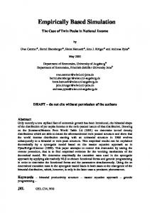
3.3.The Fault Simulator The Fault Simulator is the core of the Fault Detector Architecture. This part of the tool injects faults according to a serial fault simulation methodology: for each fault, the entire test pattern is simulated, and outputs are compared. Several optimization can be implemented over this basic scheme, and will be the subject of further work, while the current implementation already proves the feasibility of the approach. A pseudo code description of the Fault Simulator is reported in Figure 1. ReadFaultList(); ReadTestPatterns(); InitializeSimulator(); /* simulate the good machine */ Simulate(good); StoreOutputs(good); for(each fault) { /* simulate the faulty machine */ InjectFault(fault); Simulate(fault); if (CompareOutputs(good, fault) == DIFFER) UpdateFaultList(fault, DETECTED); else UpdateFaultList(fault, UNDETECTED); }
Figure 1: Fault Simulator Algorithm
3.4.Fault Injection Strategy The core of the Fault Simulator is the Fault Injection procedure. Several different approaches for injection of permanent faults in VHDL descriptions are possible, some of which have already been proposed in the literature: • Changing the VHDL code: original VHDL instructions are enriched by the code necessary to inject the fault and new input signals are added to control fault injection [FiFu00]. This technique significantly slows down simulation, because the additional source lines are always simulated, also when they are not used to inject the fault. • Modifying the simulator: the code necessary to inject and detect faults is added into simulator source code. This technique is probably the fastest fault injection methodology, and promises to simulate each faulty machine as fast as the fault free circuit, and is extremely powerful, because one may change any parameter or register during simulation. The problem of this technique is the availability of the source code of a good simulator.
• Interacting with the simulator: faults are injected through the simulator user interface using simulation commands. This technique is less powerful than modifying the simulator, but during simulation it is nearly as fast. In fact, no additional source code is present and commands are active only when the fault is injected. Our fault injection system belongs to the third methodology. Fault injection is made possible by creating routines that change the target signal/variable bit value during simulation, using the simulator scripting language (TCL), when a given target assignment instruction is executed. The chosen fault injection methodology must face various issues derived from the fault model, from VHDL Semantics and from the simulator itself. The chosen fault model considers both input signals and internal signals or variables: while the fault model definition treats them uniformly, form the implementation point of view they are different. The former ones, subject of no assignment instruction, do not correspond to a source code line identifiable as target during the simulation, while the latter may be written several times in the VHDL description, thus preventing a statically “forced” assignment of the faulty bit. Two different fault injection methods must therefore be used: one for input signals and one for internal signals or variables. Input signals can be modified before simulation starts, but internal variables and signals must be changed during simulation, whenever the target assignment instruction is executed. VHDL semantics specify that signals change at wait statements and variables change immediately. Consequently internal signals and variables must be treated in different ways during fault injection. Variables can be changed immediately after the execution of an assignment instruction; signals instead may be changed only just before the execution of the wait statement (or of the last line of the process, if the wait statement is implicit). The simulator limits interaction to the commands exposed through the scripting user interface. All the commands necessary to inject the fault must therefore respect the syntax and the timing of the simulator. Specifically, the ModelSim simulator accepts simulation commands and TCL routines. In our case, fault injection is performed through insertion of appropriate breakpoints at target instructions. Due to the above restrictions, we use two different approaches to inject faults: pre-simulation fault injection for input signal faults and run-time fault injection for internal faults. Fortunately, no distinction needs to be made concerning the data type of the involved signals and variables, since the simulator interface allows
us to treat all object as bit vectors, regardless of their original type (bit, bit vector, integer, enumerated, …). Pre-simulation fault injection consists of changing the target bit value of an input signal before simulation starts (during the waveform definition phase) forcing it at the stuck-at value. Pre-simulation fault injection is fast as a normal simulation because no delay is added to inject faults. Run-time fault injection consists of changing the target bit value of the assignment instruction selected during the simulation. Breakpoints are used in this case: before simulation starts, a breakpoint is set on the VHDL source line where fault is located. The Fault List file contains all the information necessary to injected the fault. Embedded in the breakpoint instruction there are two different routines depending on the type (variable or signal) of the assignment instruction target. If the target is a variable, the instruction is executed, then the given bit of the variable is changed and simulation is continued. If the target is a signal a more sophisticated doublebreakpoint technique is needed, to avoid modifying the signal values in advance with respect to VHDL signal propagation semantics. In the double-breakpoint technique, a breakpoint is set at the source code line where the wait statement or the last instruction is placed and simulation continues without modifying anything. This new breakpoint, that will be activated only when the wait statement (explicit or implicit) is about to be executed, forces the given bit of the signal to the stuck-at value and unsets itself before continuing the simulation. Run-time fault injection using the breakpoint technique slows down simulation by a really negligible amount. In fact, breakpoints are optimized by the simulator and impact on the simulation only when the target statements are executed, and the fault is injected.
4. Experimental results Starting from the proposed fault model and considering all the constraints described above, we implemented two programs, the Fault List Generator and the Fault Simulator. The implementation consists of about 300 lines of C code for VHDL code analysis and Fault List creation, linked to the LEDA LPI interface and interacting with the ModelSim simulator, and of 700 lines of C code for the Fault Simulator, that is interfaced to the ModelSim simulator through Unix pipes. To show the feasibility of the Fault Simulation approach, we selected a subset of the ITC’99 VHDL benchmarks [D&T2000], whose characteristics are summarized in Tab. 1. The first columns report some data about the RT-level descriptions, in terms of VHDL
lines, VHDL processes (with hierarchy unflattened), and overall number of extracted basic blocks. To have a better idea about circuit size, we synthesized the circuits with the Synopsys Design Compiler; data about the resulting gate-level descriptions are reported in the last columns, in terms of number of Primary Inputs, Primary Outputs, Flip-Flops, combinational gates, and uncollapsed and collapsed stuck-at faults. We extracted the fault lists for the chosen subset of benchmarks, and fault simulated them with a sample of pseudo-random input sequences. In the experiments we performed, the Test Pattern consisted of 500 pseudorandom vectors arranged as 5 independent sequences. A reset sequence was applied between each couple of adjacent sequences. The results obtained by running the Fault Simulator on a Sun Ultra 5 running at 333 MHz with 256MB or memory are reported in Tab. 2. For each circuit we report the percentage of tested targets on the RT-level description and the CPU Time required by the Fault Simulator, including CPU time spent by the VHDL simulator. The experiments show the feasibility of the proposed fault simulation methodology: without modifying the VHDL code nor the VHDL simulator, we are able to compute the effects of faults on assignment instructions. Even with this simple random test bench, the simulator already shows different fault coverage figures, allowing us to foresee the random pattern testability in the initial phases of the design. For instance, we can argue that the b06 circuit is random pattern resistant, and also b03 and b09 are difficult to test. Due to the currently implemented serial fault simulation approach, CPU times are nearly equal to the time needed to simulate the test pattern on the fault free circuit, times the number of faults in the fault list. Although the fault injection procedures based on breakpoints are an efficient solution, the current version of the rest of the algorithm is still at a prototypical stage, and currently implements a straightforward serial fault simulation algorithm. In order to reduce the required CPU time, several optimizations can be implemented by building upon the simulator scripting mechanisms. Some optimization techniques that will be explored in the near future are fault collapsing and untestable faults identification, early output comparison for halting simulation at the first difference, late simulation start to skip in the simulation of faulty machine the initial subset of vectors that does not excite the fault, and so on.
5.Conclusions This paper presented an approach to fault simulation of RT-level description based on exploiting the existing
debug mechanisms of commercial VHDL simulators. With a relatively moderate effort, an effective fault simulator can be built by properly programming a VHDL simulator, with a negligible overhead on simulation time. The implemented fault simulation system is able to simulate a refined version of the widely used observability-enhanced statement coverage metric, where observability is explicitly taken into account in an exact manner. Experimental results prove the feasibility of the approach, and show that access to the source code of a VHDL simulator or modifications of the VHDL code are not required in order to compute faulty responses from a digital circuit. The efficiency of VHDL simulation cores and the versatility of their user interfaces open up the possibility of greatly optimizing the efficiency of the proposed approach.
References [Beiz90] [CPSo97]
[CSSq00]
[CSSq00b]
[DGKe96]
[FADe99]
[FDKe98]
B. Beizer, Software Testing Techniques (2nd ed.), Van Nostrand Rheinold, New York, 1990 F. Corno, P. Prinetto, M. Sonza Reorda, “Testability analysis and ATPG on behavioral RT-level VHDL,” Proceedings IEEE International Test Conference, 1997, pp. 753-759 F. Corno, M. Sonza Reorda, G. Squillero, Exploiting ITC’99 benchmarks for developing an RT-level ATPG tool, to appear on IEEE Design & Test, Special issue on Benchmarking for Design and Test, June 2000 F. Corno, M. Sonza Reorda, G. Squillero, High-Level Observability for Effective High-Level ATPG, VTS-2000: 18th IEEE VLSI Test Symposium, May 2000 S. Devadas, A. Ghosh, K. Keutzer, “An Observability-Based Code Coverage Metric for Functional Simulation,” Proceedings IEEE/ACM International Conference on Computer Aided Design, 1996 F. Fallah, P. Ashar, S. Devadas, “Simulation Vector Generation from HDL Descriptions for Observability-Enhanced Statement Coverage,” Proceedings 35th Design Automation Conference, 1999, pp. 666-671 F. Fallah, S. Devadas, K. Keutzer, “OCCOM: Efficient Computation of Observability-Based Code Coverage Metrics for Functional Verification,” Proceedings 34th Design Automation Conference, 1998
[FFSc98]
[FiFu00]
[RiUc96]
[SGTT00] M.B. Santos, F.M. Gonçalves, I.C. Teixeira, J.P. Teixeira, “RTL-based Functional Test Generation for High Defect Coverage in Digital SoC,” IEEE European Test Workshop, 2000 [TAZa99] P. A. Thaker, V. D. Agrawal, M. E. Zaghloul, “Validation Vector Grade (VVG): A New Coverage Metric fo Validation and Test,” Proceedings 15th IEEE VLSI Test Symposium, 1997, pp. 182-188
F. Ferrandi, F. Fummi, D. Sciuto, “Implicit Test Generation for Behavioral VHDL Models,” Proceedings IEEE International. Test Conference, 1998 A. Fin, F. Fummi, “A VHDL Error Simulator for Functional Test Generation,” Proceedings of the Design, Automation and Test Conference, 2000, pp. 390-395 T. Riesgo, J. Uceda, “A Fault Model for VHDL Descriptions at the Register Transfer Level,” Proceedings of EURODAC/EURO-VHDL, 1996
Circuit
VHDL Lines Proc BB
b01 b02 b03 b04 b06 b07 b08 b09
110 70 141 102 128 92 89 103
1 1 1 1 1 1 1 1
PI PO
28 2 17 1 27 4 23 11 25 2 21 1 14 9 16 1
2 1 4 8 6 8 4 1
FF 5 4 30 66 9 49 21 28
GATE GATES Total Collapsed Faults Faults 46 258 127 28 150 64 149 822 382 597 3,356 1,477 60 302 151 420 2,404 1,120 167 918 439 159 900 417
Table 1: Benchmark characteristics
Circuit b01 b02 b03 b04 b06 b07 b08 b09
Fault Simulation Detected Total Faults Coverage [%] Faults 112 132 84.85 61 76 80.26 119 236 50.42 310 412 75.24 48 198 24.24 218 298 75.24 98 130 75.38 138 286 48.25 Table 2: Fault simulation results
CPU Time 474.24 311.74 1,215.91 3,611.79 288.54 940.45 705.05 1,471.57