FORMAL VERIFICATION AND VALIDATION OF INTERACTIVE SYSTEMS SPECIFICATIONS From Informal Specitications to Formal Validation Yamine AÏT-AMEUR 1, Benoit BREHOLÉE 2, Patrick GIRARD 1, Laurent GUITTET 1 and Francis JAMBON 3 1) LISI / ENSMA, BP 40109, Téléport 2, 86961 Futuroscope cedex, France 2) ONERA-CERT-DTIM, 2 Avenue Edouard Belin, BP 4025, 31055 Toulouse cedex, France 3) CLIPS-IMAG, BP 53, 291 avenue de la bibliothèque, 38041 Grenoble cedex 9, France E-mail: {yamine, girard, guittet}@ensma.fr,
[email protected],
[email protected]
Abstract:
This paper proposes a development process for interactive systems based both on verification and validation methods. Our approach is formal and use at first the B Method. We show in this paper how formal B specifications can be derived from informal requirements in the informal notation UAN. Then, these B specifications are validated using the data oriented specification language EXPRESS. Several scenarios can be tested against these EXPRESS specifications.
Key words:
B Method, EXPRESS, UAN, interaction properties, verification, validation, formal specification of interactive systems.
1.
INTRODUCTION
Graphical user interfaces relying mostly on software, are being more and more used for safety-critical interactive systems –for example aircraft glass cockpits– the failure of which can cause injury or death to human beings. Consequently, as well as hardware, the software of these interactive systems needs a high level of dependability. Besides, on the one hand, the design process must insure the reliability of the system features in order to prevent disastrous breakdowns. On the other hand, the usability of the interactive system must be carefully carried out to avoid user misunderstanding that can
2
Yamine AÏT-AMEUR 1, Benoit BREHOLÉE 2, Patrick GIRARD 1, Laurent GUITTET 1 and Francis JAMBON 3
trigger similar disastrous effects. So, the software dependability of these safety-critical interactive systems rely as well on safety as on usability properties. Our work focuses on the use of formal techniques in order to increase the quality of HCI software and of all the processes resulting from the development, verification, design and validation activities. In past workshops and conferences, we presented our approach through papers dealing with formal specifications of HCI software [4], formal verification of HCI software [5], test based validation of existing applications [19], This paper addresses another topic not tackled yet by our approach: design and formal validation of formal specifications with respect to informal requirements. This work completes the whole development process of a HCI software. Indeed, our approach uses the B formal technique for representing, verifying and refining specifications [4, 5, 19], test based validation of existing applications [19], secure code generation [18] and integration of formal approaches [12]. This paper starts from the translation of the requirements in the UAN notation [15] and shows how B specifications can be derived from. Then, the EXPRESS formal data modeling language [11] is put into practice for the validation of the derived B specifications. We show how the B specifications can be translated to EXPRESS code which allows validation. This paper is structured as follows. Section 2 reviews the different notations and formal techniques that have been experienced on HCI. Next section gives the informal requirements of a case study and its representation in the UAN notation. Section 4 presents the B technique and the specifications of the case study in B. Section 5 is related to validation. It presents the formal data modeling technique EXPRESS which allows the validation of the B specifications. We show how an automatic translation from B to EXPRESS can be performed and how this technique is applied to our case study. The result is a set of EXPRESS entities that are checked against various scenarios. Last, we conclude on the whole suggested approach.
2.
NOTATIONS AND TECHNIQUES IN HCI: A BRIEF STATE OF THE ART
2.1
Notations & Formal techniques
In order to express HCI software requirements, several notations were suggested. As examples, MAD (for “Méthode Analytique de Description”)
Formal verification and validation of interactive systems specifications
3
[27] and HTA (for Hierarchical Task Analysis) [29] use a hierarchical decomposition of user tasks. On the other side, a notation like UAN [15] and its extension XUAN [13] allow the description of not only the interface feedback, but of the user behaviors as well. UAN specifications record the state of the interface and tasks are described as state evolutions. This state orientation of UAN facilitates translation to state based formal techniques –B for example. Several techniques were used in the HCI area. These techniques differ from some point of views: semantics –algebraic or state based– verification –incremental proof or fully automatic proof– etc. Some of these techniques can be summarized in the following. On the one hand, the first techniques are state based. They were based on automata through statecharts [31] and ATN [30] [14], Petri Nets [2] [23]. They have been extended to support temporal logics to allow automatic model checking like in CTL* [25], XTL [7] and SMV [8] [22], or with the Lustre language [26]. The previous techniques support code generation and automatic proving. Other techniques supporting state based semantics and incremental proving and refinement like Z [20], VDM [21] or B [5] were suggested. On the second hand algebraic techniques have been applied with LOTOS [24, 25] for describing HCI software. The proofs are achieved by rewriting and refinement is performed by transformation. Other techniques based on higher order type systems have been experienced. All these techniques cover a limited part of the development of an HCI. Our approach does not use only one technique, but it suggests to use several techniques which cooperate, choosing each technique where it has proved to be most efficient.
2.2
Our approach
Our approach uses the B technique. B supports formal specifications, refinement from specifications to code and property verification through the proof of the generated proof obligations. Specifications are derived from the informal UAN notation and are validated using the EXPRESS data modeling language.
4
Yamine AÏT-AMEUR 1, Benoit BREHOLÉE 2, Patrick GIRARD 1, Laurent GUITTET 1 and Francis JAMBON 3
Requirements
Conception Test-Based Validation
UAN
Informal Specifications
Scenarii Validation
Derivation
B
Formal Specifications
Translation
Refinement Computer Program
Compilation
Formal Spécifications
Express
Scope of this article
Source Code
Figure 1: Scope of this article in the approach we suggest for handling the development and validation of HCI
Formal specifications, property verification and refinement from specification to code have been have been presented in [4, 5, 19] respectively. This paper presents the last point: deriving specifications from semi-formal notations and their validation in EXPRESS. This paper completes the whole developed approach described in figure 1.
3.
CASE STUDY AND THE USER ACTION NOTATION
3.1
The case study: the Rangeslider
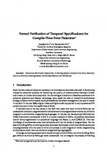
An usual slider –with a single cursor– is a graphical toolkit widget used by interface designers to allow the specification of a value in an interval. The Rangeslider [3] used by Spotfire™ (http://www.spotfire.com) is an enhanced version of this classical slider, i.e., it supplies two cursors –see fig. 2– in order to allow users to select not only a single value, but a range of values. This new widget is used by interface designers to implement easy-to-use zoom or filtering functions. A Rangerslider user can interact with the widget by the way of three different kinds of actions: – Move one cursor: the user moves one of the two cursors, to the left or to the right. As a consequence, the area of the center zone expands or reduces. The moved cursor cannot cover over the other cursor nor exceed the widget length.
Formal verification and validation of interactive systems specifications
5
– Move the center zone: the user moves the center zone, and at the same time both cursors come after it. So the area of the center zone remains unchanged. No cursor can exceed the widget length. – Select a value in outer zones: the user clicks in one of the outer zones –MinZone or MaxZone– and the closest cursor moves at the selected point. As a consequence, the area of the center zone expands or reduces. MinCursor
x_slider
MinZone
MaxCursor CenterZone
MaxZone
y_slider width
val_min
s_min
s_max
val_max
length
Figure 2: RangeSlider scheme —with variables names used both in the UAN, B and EXPRESS specifications.
3.2
The User Action Notation
The User Action Notation is an interaction-design notation. Hix et al. suggest that “the UAN is intended to be written primarily by someone designing the interaction component of an interface, and to be read by all developers, particularly those designing and implementing the user interface software” [15]. The UAN is user- and task-oriented. A UAN specification describes, at the physical level, the user actions and their corresponding interface feedback and state changes. A typical UAN specification in a three-columns table which must be read from left to right and from top to bottom. The first column is dedicated to the user actions –mouse-clicks, keystrokes, etc.– the second one to the interface feedback –icon highlighting, widget display, etc.– and the third one to the interface state –name of the selected icon, position of a slider, etc. User actions as well as interface feedback have a specific representation. User actions represent user interactions with devices as mouse or keyboard. Among the UAN user actions, we use in §3.3 the following: – [X] context of the object X – ~[X] move cursor in the context of object X – ~[x,y in X] move cursor to (arbitrary) point within object X – Mv depress the mouse button – M^ release the mouse button – * the action can be repeated 0 or more times
6
Yamine AÏT-AMEUR 1, Benoit BREHOLÉE 2, Patrick GIRARD 1, Laurent GUITTET 1 and Francis JAMBON 3
Interface feedback represents the system actions that are observable. Among the UAN interface feedback, we use: – X! highlight object X – X -! unhighlight object X – X>~ object X follows (in dragged by) cursor – display(X) display object X – erase(X) erase object X – redisplay(X) equivalent to erase(icon) and then display(icon) – @x,y at point x,y (e.g. to display X) – condition : action the action is triggered if condition is true – (…) grouping mechanism In the example table 1 below, in order to select a file, the user moves the mouse pointer to the file icon “file2“ and depresses the mouse button. Then the file icon is highlighted and all other icons are unhighlighted. The interface state –the name of the selected file– is updated when the user depresses the mouse button. Table 1: UAN specification of the task “select icon” TASK: select file USER ACTIONS
INTERFACE FEEDBACK
~[file2] M^
file2 !
INTERFACE STATE
" file2’ ≠ file2 : file2’ -! Mv
3.3
selected = file
Specification of the Range-Slider in the UAN
The three tables below –table 2 to table 4– are the UAN specifications of the three user interactions described in §3.1. In fact, a full UAN specification must comprise five tables –one table for each user interaction. However the two pairs of UAN tables for cursor and outer zones are so similar that one table of each pair has been omitted. In these tables, Rangeslider is the name of the whole slider object and ∆x is the spatial increment on the abscissa axis. 3.3.1
Move one cursor (MinCursor)
In order to move the left cursor –MinCursor– the user must move the mouse button in the context of the MinCursor object. Then, he can depress the mouse button and drag the cursor. The MinCursor follows the mouse
Formal verification and validation of interactive systems specifications
7
pointer and the center zone must be redisplayed. At each increment, the value of the s_min variable is updated. Table 2: UAN specification of the task “move MinCursor” TASK: move MinCursor USER ACTIONS
INTERFACE FEEDBACK
~[MinCursor] Mv
MinCursor !
~[x,y in RangeSlider]*
0NAT ٠width Πsliders-->NAT ٠length Πsliders-->NAT ٠val_min Πsliders-->NAT ٠val_max Πsliders-->NAT ٠s_min Πsliders-->NAT ٠s_max Πsliders-->NAT ٠/* Safety properties of the slider */ " sl.(sl:sliders =>(val_min(sl) >= 0)) ٠" sl.(sl:sliders =>(val_min(sl) (s_max(sl) (x_slider(sl) Π1..screen_width)) ٠" sl.(sl:sliders =>(y_slider(sl) Π1..screen_height)) ٠" sl.(sl:sliders =>(x_slider(sl)+length(sl) Π1..screen_width)) ٠" sl.(sl:sliders =>(y_slider(sl)+width(sl) Π1..screen_height))
The initialization clause initializes all the variables of the model to the empty set. One can be astonished why functions are initialized to the empty set. In B, accessing functions are considered as subsets of Cartesian products, therefore, they can be initialized to an empty set. INITIALISATION sliders := {} || x_slider := {} || y_slider := {} || length := {} || width := {} || val_min := {} || val_max := {} || s_min := {} || s_max := {}
The first operation allows to create a range slider with X X , Y Y as coordinates of its left up corner. Its length and width are respectively given by the parameters L E N G T H and WIDTH. Finally, V M I N and VMAX parameters indicates the minimal and maximal values of the range. The slider is created with VMIN and VMAX as initial minimal and maximal values. A preconditon ensures that the parameters are correctly typed and the
Formal verification and validation of interactive systems specifications
13
invariant is maintained. It ensures that the creation of a range slider is correctly performed. OPERATIONS create(XX,YY,LENGTH,WIDTH,VMIN,VMAX)= PRE sliders ≠ SLIDERS Ÿ XX Œ NAT Ÿ YY Œ NAT Ÿ WIDTH Œ NAT Ÿ LENGTH Œ NAT Ÿ VMIN Œ NAT Ÿ VMAX Œ NAT Ÿ VMIN >= 0 Ÿ VMIN < VMAX Ÿ VMAX val_min(one_slider) Ÿ new_left_min_value < s_max(one_slider) THEN s_min(one_slider) := new_left_min_value END; .... END
14
Yamine AÏT-AMEUR 1, Benoit BREHOLÉE 2, Patrick GIRARD 1, Laurent GUITTET 1 and Francis JAMBON 3
Other operations related to the range slider have been described in this abstract machine. Moreover, the whole application is represented by several abstract machines not presented in this paper. Indeed, abstract machines related to the mouse management, to the direct manipulation and so on have been described. Finally, notice that the abstract machine described in B and presented in this paper has shown that it is possible to: – ensure that a range slider remains in the screen limits, – ensure that the low and up values of a range slider respect the definition of a range, – move the low value, of a range slider to the left in order to decrease its left value, by running the corresponding operation. For the whole developed abstract machine, the proof obligations have been generated. They all have been automatically proved. However, this specification has not been built at the first attempt. We had to enrich the preconditions and to remove other preconditions. Indeed, the prover behaves following: – preconditions are not complete, therefore the proof cannot be achieved, – preconditions are contradictory, then the user has to make new choices and to check the requirements. Finally, about 40 proof obligations are generated for this application. We had to prove only 2 proof obligations using the interactive prover, i.e., "by hand". This shows that when the application is well specified following sound software engineering concepts, the proof phase can be considerably reduced. All these properties are safety properties. In the next section we address the problem of the validation of such formal specifications that is not supported by the B formal technique.
5.
THE EXPRESS TECHNIQUE AND VALIDATION OF SPECIFICATIONS
Describing data models is a major concern of the data management and knowledge management areas. Several formalisms, models and techniques allow to represent data and/or knowledge. For example, OMT, UML and so on are used to represent information systems while KIF, KADS and so on are techniques for knowledge representation. The definition of such formalisms for representing information systems requires a set of concepts usually needed. These concepts are related to structure, description and
Formal verification and validation of interactive systems specifications
15
behavior. Structure defines the organization of the data in the information system. For example classification or object orientation or relational databases are ways of structuring information. Description is related to the properties of the structured information. It is defined by the set of the properties that a given description has. Attributes in classes or in relational tables are ways to describe different classes or tables. Behavior gives the information on how the data behave. Behavior is obtained either by giving a function which shows how data evolve (constructive approach) or by giving constraints on the data to restrict the behavior to the licit data. These three concepts require the definition of a language or any other formalism which allows to handle them. It is highly suitable that this language is processable. EXPRESS is a formal data modeling language that handles these three kinds of knowledge. A data model in EXPRESS is represented by a set of schemas that may refer to each other. Each schema contains two parts. The first part is a set of entities that are structured in an object oriented approach with multiple inheritance. The second part is a procedural part which contains procedures, functions and global rules.
5.1
The EXPRESS data modeling language
The EXPRESS language has been designed in the context of the STEP (STandard for the Exchange of Product model and data) international project which aims at describing formal models for exchanging product data. Moreover, this language can be used for the specification of several applications in computer science areas. This section focuses on the constructions we use in the reminder of the paper. More details about the definition of this language can be found in [6, 28]. The EXPRESS language focuses on the definition of entities –types– which represent the objects –classes– we want to describe. EXPRESS is type oriented: entity types are defined at compile time and there is no concept of meta-class. Each entity is described by a set of characteristics called attributes. These attributes are characterized by a domain and constraints on these domains. An important aspect of these entities is that they are hierarchically structured allowing multiple inheritance as in several object oriented languages. This part of the specification describes the structural and the descriptive parts of the domain knowledge. On the other hand, it is possible to describe processes on the data defined in the entities by introducing functions and procedures. These functions are used to define constraints, pre-conditions and post-conditions on the data. They are also used to specify how the values of some properties that may be
16
Yamine AÏT-AMEUR 1, Benoit BREHOLÉE 2, Patrick GIRARD 1, Laurent GUITTET 1 and Francis JAMBON 3
derived from the values of other properties. This part of the specification describes the procedural part of the domain knowledge. Finally, in EXPRESS, entities –data– and functions –processes– are embedded in a structure called a SCHEMA. These schemes may reference each other allowing a kind of modularity and therefore specification in the large possibilities. 5.1.1
Entity definition
In EXPRESS, entities are defined in terms of attributes. Indeed, a set of attributes (may be an empty set) is assigned to each entity. Each attribute has a domain (where it takes its values) defining a data type. It can be either a simple domain –integer, string– or a structured domain –lists, sets, bags– (hard encoded in EXPRESS) or an entity type meaning that an attribute is of type of another entity. We syntactically write: SCHEMA foo1; ENTITY A; att_A :INTEGER; INVERSE att_I#: B FOR att_3#; END_ENTITY; END_SCHEMA;
ENTITY B; att_1:REAL; att_2:LIST [0:?] OF STRING; att_3:A; END_ENTITY;
Informally, the entity B has three attributes: an integer, a list of string and a pointer to another entity A which has only one integer attribute. att_I is an inverse attribute of entity A corresponding to the inverse link defined by attribute att_3 in entity B. Semantically, an entity has a model. In the EXPRESS community, the model is named a physical file. The model consists of a set of entity instances with explicit instance identity. The attribute values are either literal values of the EXPRESS simple or structured built-in types or references to other entity instances. Instead of entering into deep semantic details, we give an example of a model (physical file) which can be associated to the previous entity definitions. Let us consider a particular representation, named instance, of the entity B, where att_1 evaluates to 4, att_2 is the list ( 'hello', 'bye' ) and att_3 points the particular instance of the entity A where its att_A attribute evaluates to 3. Then, the model (physical file) associated to these particular instances of the entities A and B is described by # 1=A(3, #2) ; # 2=B(4,('hello','bye') ,# 1);
Formal verification and validation of interactive systems specifications 5.1.2
17
5.1.2. Derived attributes
As it is the case for several object oriented languages, it is possible to have derived attributes in the entity definitions. For example, we can derive in entity B2 (assumed to be defined in the same schema Foo1) a Boolean attribute stating whether or not the length of the att_2 list is equal to the integer attribute att_A defined in entity A by writing: ENTITY B2; att_1:REAL#; att_2:LIST[0:?] OF STRING; att_3: A#; DERIVE att_4 :BOOLEAN:= (SELF.att_3\A.att_A=SIZEOF(SELF.att_2))#; END_ENTITY;
where: – SELF is an EXPRESS keyword representing a variable which designates the current entity, – . is the dot notation to access the attribute of an entity, – \ character allows to access super-type, – and SIZEOF is an EXPRESS built-in function which gives the length of an aggregate data type. The derived (computed) attributes do not physically appear in the model (physical file). 5.1.3
5.1.3. Constraining entities
It is possible to limit the allowed population (elements) of the models to those instances that satisfy some stated constraints. They are introduced thanks to the WHERE clause of EXPRESS that provides for instance invariant, and to the global RULE clause that provides for model invariant. Let us assume that the allowed values for att_A are [1..10] and that exactly two instances shall have an attribute value 1, we may write (QUERY is a built-in iterator on class): ENTITY A#; att_A: integer; WHERE (SELF.att_A>=1) and (SELF.att_A