ment, Hardware/Software (HW/SW) interface models, as the test harnesses ...
interface specifications, where we propose a semantic model, relative atomicity,
to ...
Formalizing Hardware/Software Interface Specifications Juncao Li1∗ , Fei Xie2 , Thomas Ball1 , Vladimir Levin1 , and Con McGarvey1 1
Microsoft Corporation, Redmond, WA 98052, USA. Email: {juncaoli, tball, vladlev, conmc}@microsoft.com 2 Dept. of Computer Science, Portland State University, Portland, OR 97207, USA. Email:
[email protected]
Abstract—Software drivers are usually developed after hardware devices become available. This dependency can induce a long product cycle. Although co-simulation and co-verification techniques have been utilized to facilitate the driver development, Hardware/Software (HW/SW) interface models, as the test harnesses, are often challenging to specify. Such interface models should have formal semantics, be efficient for testing, and cover all HW/SW behaviors described by HW/SW interface protocols. We present an approach to formalizing HW/SW interface specifications, where we propose a semantic model, relative atomicity, to capture the concurrency model in HW/SW interfaces; demonstrate our approach via a realistic example; elaborate on how we have utilized this approach in device/driver development process; and discuss criteria for evaluating our formal specifications. We have detected fifteen issues in four English specifications. Furthermore, our formal specifications are readily useful as the test harnesses for co-verification, which has discovered twelve real bugs in five industrial driver programs.
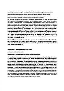
I. I NTRODUCTION In modern computer systems such as PC, devices and drivers are usually manufactured separately, because their development processes need highly different expertise. Driver development commonly requires the device’s presence in order to exercise the functionalities and test the implementation conformance to Hardware/Software (HW/SW) interface protocols. To alleviate such dependency and shorten the product cycle, co-simulation and co-verification techniques have been utilized to facilitate the driver development [1], [2]. One key challenge is to develop the test harnesses, i.e., HW/SW interface models. Such models need to be abstract enough to ensure the test efficiency; however, they also should be accurate to avoid false positives. Currently, English is the de facto language for specifying HW/SW interface protocols. Since many such protocols are public standards, their English specifications need to be selfexplanatory. However, English does not have formal semantics; therefore these specifications commonly contain ambiguities and inconsistencies. Figure 1 illustrates an excerpt from the English document of the Intel 8255x 10/100Mbps Ethernet Controller Specification [3]. This excerpt describes how the shared memory between hardware and software should be operated by hardware when a CU/RU (Command Unit/Receive Unit) command is issued from software. There are two issues: First, the content of Table 15 is inconsistent with its title (underlined, the RU and CU difference). Second, the CU HPQ Start command is neither defined nor mentioned in any other part of this document. This is quite confusing
Fig. 1.
Excerpt from Intel Ethernet Controller document.
when compared to the CU Start command. Such kind of specification issues pervasively exist (see Section VIII for details) in various English documents for HW/SW interfaces. These issues can cause confusion, produce bugs, and lead to product failures. Therefore, formal HW/SW interface models are greatly desired to augment English specifications. We characterize the problems in device/driver development and present a practical approach to formalizing the HW/SW interface specifications, where B¨uchi Automata (BA) [4] and Labeled Pushdown Systems (LPDSs) [5] serve as the foundational formal models for hardware and software respectively. Our approach has the following contributions: •
•
•
•
Relative atomicity. We propose a semantic model, relative atomicity, to capture the various atomicity levels in HW/SW interface designs. Relative atomicity can greatly simplify the concurrency model for HW/SW interface specifications by excluding infeasible context-switches. Specification of HW/SW interface protocols. We develop a formal specification approach for HW/SW interface protocols and demonstrate it via a realistic example. We design a specification language, modelC, that utilizes the C semantics with three restrictions to achieve finite state and two extensions to support relative atomicity and nondeterminism. Protocol coverage. We strictly follow HW/SW interface protocols to specify formal models. Therefore, all HW/SW behaviors allowed by protocols are captured by formal models. This is very important to ensure the test coverage when formal models are used as test harnesses. Application and evaluation criteria. We present how our approach can be applied to the device/driver development
process and discuss four criteria for evaluating our formal specifications. One key idea is the MODEL-DOC ratio that helps establish a quantitative relation between formal specifications and English specifications. We have formalized four types of HW/SW interfaces, such as Ethernet controller devices/drivers and USB (Universal Serial Bus) devices/drivers. We detected fifteen issues in the English specifications. Furthermore, our formal specifications are readily useful as the test harness to verify five Windows driver implementations with respect to their device behaviors. All the drivers had been well tested. However, our co-verification tool, CoVer [6], still discovered twelve real bugs. These specification issues and driver bugs (confirmed by Windows architects) are previously unknown to either the hardware or software engineers.
Kuznetsov, et al. [1] have developed HW/SW interface models to test Windows drivers via symbolic execution. In their approach, most hardware design logic is abstracted away by non-determinism; therefore, the interface models cannot serve as HW/SW interface specifications. Furthermore, false bugs may be reported due to the over abstraction of the hardware behaviors. In practice, finite state machines, such as ω-automata and BA [4], are common representations for hardware. PDSequivalent models [12] are common representations for software. For example, COSPAN/FormalCheck [14] uses ωautomata as the formal representation of hardware. The SLAM engine [15] verifies C programs for safety properties, where Boolean program, a PDS-equivalent model, is used as the software representation. Furthermore, concurrent PDS is a suitable model for multi-threaded software, since each software thread contains a stack that needs to be represented. Although verification of concurrent PDS is undecidable [13] in general, decidability can be achieved by bounding the number of context-switches [16].
Outline. The rest of this paper is organized as follows. Section II discusses the related work. Section III introduces the background of this paper. Section IV summarizes a common development process for devices/drivers in industrial settings. Section V presents the specification techniques we have designed for HW/SW interfaces. Section VI demonstrates our formal specification approach via a realistic example. Section VII elaborates on the application of our approach in the device/driver development process as well as the criteria that we have proposed for evaluating our formal specifications. Section VIII presents the evaluation results. Section IX concludes and discusses the future work.
III. BACKGROUND This section introduces the background of our research. First, we discuss the formal representations for hardware and software respectively. Second, we introduce the Windows driver framework that will be used as examples throughout the rest of this paper. A. Formal Representations ¨ Buchi Automaton (BA) as the hardware representation. A BA B [4] is a tuple (Σ, Q, δ, q0 , F ), where Σ is the input alphabet, Q is the finite set of states, δ ⊆ (Q × Σ × Q) is the set of state transitions, q0 ∈ Q is the initial state, and F ⊆ Q is the set of final states. B accepts an infinite input string iff (if and only if) it has a run over the string that visits at least one σ of the final states infinitely often. We use q → q ′ to denote a ′ BA transition from state q to q with the input symbol σ. Labeled Pushdown System (LPDS) as the software representation. An LPDS P [5], is a tuple (I, G, Γ, ∆, ⟨g0 , ω0 ⟩), where I is the input alphabet, G is a finite set of global states, Γ is a finite stack alphabet, ∆ ⊆ (G × Γ) × I × (G × Γ∗ ) is a finite set of LPDS rules, and ⟨g0 , ω0 ⟩ ∈ G × Γ∗ is the initial configuration. LPDS extends PDS in such a way that an LPDS can take input. A configuration of P is a pair ⟨g, ω⟩ representing a software state, where g ∈ G is a global state and w ∈ Γ∗ is a stack content. An LPDS rule is written as τ ⟨g, γ⟩ ,→ ⟨g ′ , w⟩, where τ ∈ I, ((g, γ), τ, (g ′ , w)) ∈ ∆, and ⟨g, γ⟩ is referred to as the head of this rule. Concurrent Labeled Pushdown System (CLPDS). A CLPDS CP, as the product of multiple LPDS, is a tuple (I, G, Γ, ∆0 , . . . , ∆N , ⟨g0 , ω0 , . . . , ω0 ⟩), where N > 0. A CLPDS CP is different from an LPDS P in the sense that CP has more than one stack. For each stack, there is a set of LPDS rules ∆i , where 0 ≤ i ≤ N . A CLPDS rule has the form of τ ⟨g, γ0 , . . . , γi , . . . , γn , ⟩ ,→CP ⟨g ′ , γ0 , . . . , ωi , . . . , γn ⟩, where τ ⟨g, γi ⟩ ,→ ⟨g ′ , ωi ⟩ ∈ ∆i . There is only one stack content
II. R ELATED W ORK There has been lots of research on formalizing interface semantics, such as I/O automata by Lynch, et al. [7], interface automata by De Alfaro, et al. [8], and ω-automata used in component-based design of embedded systems by Li, et al. [9]. Kroening, et al. [10] have used SystemC [11] to specify HW/SW interface designs. However, none of the research is suitable for representing software implementations, since the stack is not formally modeled. We model the software stack, so that our specification can closely resemble the implementation semantics of HW/SW interface. As a significant benefit, our formal specifications can be used, without any modification, as the test harness for software (resp. hardware) implementations. Therefore, many previously unknown driver bugs have been discovered by our co-verification tool. Another approach that models HW/SW interface is exemplified by Monniaux [2], where both hardware and software are specified using C programs, formally two Pushdown Systems (PDSs) [12]. The HW/SW concurrency is modeled by a straightforward composition of the two PDSs. Representing hardware also as a PDS is neither necessary nor efficient, because hardware designs do not require a stack and verification of concurrent PDS, as the product of multiple PDSs, costs much more efforts than that of a single PDS (verification of concurrent PDS is undecidable in general) [13]. Monniaux has applied this approach to verify USB host controller driver implementations; however, no real bug was found. 2
updated in a CLPDS transition. We refer to the LPDS rule that is selected to be executed in a CLPDS rule as the active LPDS rule. CLPDS can represent multi-threaded software. Synchronizing BA and LPDS (resp. CLPDS). We demonstrate how to combine the execution of BA B and LPDS P (reps. CLPDS CP). Since a CLPDS rule actually depends on its active LPDS rule, we only need to study how to combine BA transitions and LPDS rules. We define (1) the input alphabet of B as the power set of the set of atomic propositions that may hold on a configuration of P; (2) the input alphabet of P as the power set of the set of atomic propositions that may hold on a state of B; and (3) two labeling functions as follows: • LP2B : (G × Γ) → Σ, which associates the head of an LPDS rule with the set of propositions that hold on it. • LB2P : Q → I, which associates a state of B with the set of propositions that hold on it. σ Given a BA transition t = q → q ′ ∈ δ and an LPDS rule r = τ ′ ⟨g, γ⟩ ,→ ⟨g , ω⟩ ∈ ∆, they enable each other iff τ ⊆ LB2P (q) and σ ⊆ LP2B (⟨g, γ⟩). Furthermore, let r be the active LPDS rule of a CLPDS rule r′ , we also say that t and r′ enable each other.
otherwise, this type of devices are referred to as function devices, e.g., a network adapter card connected to the PCI bus. We usually refer to function devices (resp. function drivers) directly as devices (resp. drivers). For example, a PCI function device is referred to as a PCI device. IV. C OMMON D EVELOPMENT P ROCESS OF D EVICES /D RIVERS As illustrated in Figure 3, we have observed a common development process for device/driver frameworks in industrial settings, where a device/driver framework (e.g., USB) refers to a type of HW/SW interface as well as the devices and drivers that both utilize this interface. The development process has three stages:
Design HW/SW interface protocol
Devices or drivers
In-house testing Passed
Failed
DDI
Fig. 3.
Signal
Signal
Signal
Function device (e.g., mouse, network card) Fig. 2.
Post-release Stage
Development process of device/driver frameworks.
Design stage. Usually, a device/driver framework is initially designed by a group of hardware and software companies together. The HW/SW interface protocol is described in a draft English specification which is shared between these participant companies for revision. Engineers from these companies proof-read the English specification and try to identify potential problems in the HW/SW interface design.
Software Hardware
Bus device (e.g., PCI, USB) Interrupt
Certification: Conformance testing Passed
DDI (Device Driver Interface)
Intermediate hardware layers Interrupt
Development Stage
Ship the product
DDI
Intermediate software layers Interrupt
Published English specification
Released products
Bus driver (e.g., PCI, USB) ISR (Interrupt Service Routine)
Develop devices or drivers
Design Stage
Failed
Function driver (e.g., mouse, network card) ISR
Manual proof reading Passed
B. Windows Driver Framework Drivers check device status or send commands to devices by reading or writing device registers, and receive notification of state changes from devices through interrupts. In Windows [17], devices and drivers are organized through stacks as illustrated in Figure 2. Each layer of a driver stack services a ISR
Issues detected Draft English specification
Development stage. The English specification is made public after it has been agreed upon by the participant companies. The companies will start to develop their own hardware (resp. software) products for this device/driver framework based on the English specification. During this stage, other companies, who have not participated in the design stage, may also develop their own hardware (resp. software) products that are compliant with this device/driver framework. How well a product complies with the HW/SW interface protocol highly depends on the development engineers’ interpretations of the English specification. In order to further ensure the HW/SW interface compliance, a product also needs to be tested according to the English specification. Because test
A generic view of Windows device and driver stacks.
layer of the corresponding device stack. Different layers of a driver stack usually have different I/O interfaces. For example, USB drivers use Device Driver Interface (DDI) functions such as WdfUsbRetrieveConfigDescriptor to read USB device registers; PCI drivers read device registers using DDI functions such as READ_REGISTER_UCHAR. One common method to classify device (resp. driver) layers is by deciding whether devices of a layer interconnect other devices. If yes, this type of devices are referred to as bus devices, e.g., PCI (Peripheral Component Interconnect) bus; 3
engineers from different companies may have their own interpretations of the specification, the test cases vary; thus the test coverage of different products can be significantly different, so is the products’ quality in terms of the HW/SW interface compatibilities. Figure 4 illustrates such an example, which contains two excerpts respectively from a Linux driver and a Windows driver for the same hardware device, the Intel 8255x 10/100Mbps Ethernet controller. The two C functions respectively illustrated in Figure 4(a) and Figure 4(b) have the same functionality which is to issue a software command to the device; however the implementations are different. Before issuing a new command, the Linux driver always waits until the command register becomes free (this rule is indicated by the English specification); however the Windows driver does not wait before issuing any new command unless the parameter WaitForScb is set to be true, which is due to some kind of performance optimization. Obviously, the Windows driver is more efficient, because it tries to avoid unnecessary checks on hardware registers. On the other hand, it is also more challenging to maintain the driver’s correctness, because the driver developer must guarantee that when D100IssueScbCommand is called with WaitForScb being FALSE, the command register should always be free.
Post-release stage. After a product passes in-house testing, the company may choose to ship this product to market directly or send it to a third-party organization for conformance testing. Conformance testing decides whether a hardware (resp. software) product complies with the HW/SW interface protocol. Test cases are developed by engineers from the third-party organization based on the English specification. The product passes the certification if all the test cases succeed. During the development process, it is desired that a formal HW/SW interface model is present. This can help validate the HW/SW interface design, convey the HW/SW interface protocol precisely, and provide a uniform test harness for devices/drivers. V. S PECIFICATION T ECHNIQUES FOR HW/SW I NTERFACES In this section, we first discuss the types of concurrency related to HW/SW interfaces. Then, we present our approach that utilizes Transaction Level Modeling (TLM) [11] to abstract away hardware implementation details. Furthermore, we propose a semantic model, relative atomicity, to simplify the complexities of HW/SW interface specifications. We also elaborate on how we utilize the concept of non-determinism in our approach. At last, we present our specification language, modelC.
int e100 exec cmd( nic *nic, u8 cmd, dma addr t dma addr ) { int err = 0; ... spin lock irqsave( . . . );
A. Concurrency in a HW/SW System There are three types of concurrency related to HW/SW interfaces: (1) hardware concurrency; (2) software concurrency; and (3) HW/SW concurrency. They should be represented at a proper level of details in HW/SW interface specification. Hardware concurrency. Hardware is concurrent in nature and hardware concurrency exists in various levels of design abstractions. From the view point of software, there are two types of hardware concurrency: (1) concurrency between hardware modules; and (2) concurrent assignments to hardware registers. For example, an Intel Ethernet Controller [3] has modules such as command unit, receiving unit, interrupt management, etc. Although these modules are fully concurrent, they may not be driven by the same clock signal; therefore, they are asynchronous. Each module can be further divided into smaller modules or directly implemented [18]. When a module is directly implemented, its operation consists of a sequence of steps that are driven by a clock signal. The states of the module are maintained by hardware registers which are updated simultaneously upon clock cycles. How the registers should be updated each clock cycle depends on the registers’ states before the clock cycle and the transition rules specified by the hardware design. Software concurrency. Drivers are usually designed multithreaded. For example, multiple threads can run concurrently to service different requests such as interrupts from hardware and I/O requests from user applications. From the view point of hardware, there are two types of software concurrency: (1) multiple threads concurrently operate hardware, e.g., read/write hardware interface registers; and (2) an ISR
/* Previous command is accepted when SCB clears */ for (i = 0; i < E100 WAIT SCB TIMEOUT; i++) { /* If last command has been completed */ if (likely(!ioread8(&nic->csr->scb.cmd lo))) break; cpu relax(); if (unlikely(i > E100 WAIT SCB FAST)) udelay(5); } /* If last command timeout */ if (unlikely(i == E100 WAIT SCB TIMEOUT)) { err = -EAGAIN; goto err unlock; } /* Issue a new command */ if (unlikely(cmd != cuc resume)) iowrite32(dma addr, &nic->csr->scb.gen ptr); iowrite8(cmd, &nic->csr->scb.cmd lo); err unlock: spin unlock irqrestore( . . . ); return err; }
(a) Linux driver code excerpt. NTSTATUS D100IssueScbCommand( PFDO DATA FdoData, PUCHAR ScbCommandLow, BOOLEAN WaitForScb ) { // Wait for the last command to complete? if ( WaitForScb == TRUE ) { if ( !WaitScb(FdoData) ) // Wait for the command register to become free return (STATUS DEVICE DATA ERROR); // If last command timeout }
}
// Issue a new command WRITE REGISTER UCHAR ( ((PUCHAR)(FdoData->CSRAddress) + SCB COMMAND LOW BYTE), ScbCommandLow ); return (STATUS SUCCESS);
(b) Windows driver code excerpt. Fig. 4. Excerpts from the Linux and Windows drivers for the Intel 8255x 10/100Mbps Ethernet controller.
4
is invoked to service a hardware interrupt, so the currentexecuting thread will be preempted [17]. Conceptually, we can understand each thread as an LPDS. The threads together can be represented as a product of the LPDSs, i.e., a CLPDS model. Since the verification of CLPDS requires a lot more efforts than that of LPDS [13], it is desired that software behaviors are modeled using a single LPDS as much as possible. As we shall demonstrate later, the second type of software concurrency can be represented as a single LPDS following the semantic model of relative atomicity.
C. Relative Atomicity Concurrent threads usually have different execution priorities. Since higher-priority threads preempt lower-priority threads, they should be considered atomic to the lower-priority threads. Relative atomicity captures this semantic feature by stating that a higher-priority thread is relatively atomic to a lower-priority thread. In HW/SW interface designs, relative atomicity captures two ideas: (1) hardware transactions are atomic from the view point of software; and (2) ISRs for hardware interrupts are atomic to other lower-priority software routines [17] (see Figure 10 for example). Any software concurrency that follows the relative atomicity model can be represented by a single LPDS. Otherwise, a CLPDS is necessary. Relative atomicity is a very important semantic concept to help reduce the complexities in HW/SW interface specification, co-simulation, and co-verification.
HW/SW concurrency. A device and its driver run asynchronously and only transition synchronously when they interact through their interface. The HW/SW concurrency describes two situations: (1) most of the time, software and hardware transition asynchronously, so their states do not affect each other; and (2) when hardware and software interact with each other, their synchronous transition will be decided by the states of both hardware and software.
D. Using Non-determinism We utilize non-determinism mainly in two ways: (1) updating the state variables, which contributes to the dataflow of the specification; (2) deciding the conditions of branches or loops, which contributes to the control-flow of the specification. For both ways, the use of non-determinism abstracts away unnecessary details. For example, one important utilization of non-determinism in our approach is how we model the hardware concurrency.
B. Transaction Level Modeling of Hardware We use BA as the formal representation of hardware, where hardware behaviors are represented as BA transitions. We utilize the idea of TLM to specify such BA transitions. TLM is a common approach to hardware specification, where the design logic is specified by transaction functions while the implementation details such as clock signals are abstracted away.
Non-deterministic interleaving. Hardware is concurrent in nature. For example, a network card processes software command and receives data concurrently. To specify this kind of hardware concurrency, we design an approach called nondeterministic interleaving which has three steps: (1) identify the concurrent modules (e.g., command unit, receive unit, etc.) of the target hardware device; (2) specify the modules using separate C functions which we refer to as module functions; and (3) non-deterministically invoke these module functions in a hardware transaction function. When the transaction function is executed multiple times, these module functions are executed in a non-deterministic sequence. From the view point of software, the effect of hardware concurrency is modeled by the set of hardware states after non-deterministic many executions of the hardware transaction function. (see Section VI-B for examples.)
Hardware transaction. Since our goal is to specify HW/SW interface protocols, the design logic rather than the implementation details is relevant. Thus, the clock-driven semantic feature of hardware implementations is unnecessary to be preserved in our specification. For example, a data-transfer command is usually processed in multiple clock cycles; however it is only necessary to describe this command as one hardware state transition from the view point of software. We define a hardware transaction to represent a hardware state transition (i.e., a BA transition) in an arbitrarily long but finite sequence of clock cycles. Hardware transactions are atomic to software. The concept of hardware transaction preserves hardware design logic that is visible to software, but hides details that are only necessary for synthesizable Register Transfer Level (RTL) designs [18]. Hardware transaction function. Consider a hardware transaction as a BA transition, we define a hardware transaction function as a C function that describes a set of BA transitions labeled by the same input symbol. Let the current-states and next-states of a transaction function be ρ ⊆ Q representing the hardware states when entering the function and ρ′ ⊆ Q representing the hardware states when exiting the function respectively, a transaction function is formally denoted as F : Q × σ × Q, where σ ∈ Σ. Any terminating C function can be treated as a transaction function. In order to differentiate the definition of hardware transaction functions from normal C functions, we use the keyword __atomic to indicate the type of transaction functions (see Figure 6 for example).
E. The modelC Language We design a specification language, modelC, to support both the software specification and the hardware TLM specification. modelC uses C semantics with two extensions to support nondeterminism and relative atomicity. In modelC, (1) numbers are treated as bounded integers, so hardware registers can be properly modeled; (2) unbounded recursion is not allowed; and (3) dynamic memory allocation is not allowed. It is important to note that modelC is simply a C language with these extensions and restrictions. Other languages such as SystemC can also be adapted to support the formal specification following our approach. 5
VI. S PECIFYING HW/SW I NTERFACE P ROTOCOLS
when hardware updates the software interface states, and vice versa. For example, when a device raises an interrupt, the HW/SW interface will call the corresponding ISR. On the other hand, when a driver writes to a hardware interface register, the HW/SW interface will update the related hardware registers accordingly. In general, the HW/SW interface describes the synchronous transitions of hardware and software when an interface event happens.
We demonstrate how we formally specify the HW/SW interface protocols through an example, the PIO-24 digital I/O device/driver interface [19]. One important rule for our specification is to capture all possible HW/SW behaviors that are allowed by interface protocols. As illustrated in Figure 5, our formal specification has: a HW/SW interface, a hardware model, and a software model.
// hardware transaction function labeled by the input symbol // {wr_a} ∈ Σ __atomic VOID atWritePortA ( UCHAR ucRegData ) {
From software to hardware WRITE_REGISTER_UCHAR(...) => atWritePortA(...) => atWritePortB(...) ...... Σ={ {wr_a}, {rd_a}, {wr_b}, {no_evt}, ... } Software routines: Output2PortA(...) Output2PortB(...) Isr( ) ...... I ={ {intr}, {no_intr}, ... }
Software Model
HW/SW Interface
Hardware Model
// If Port A is configured as an “input” port if ( g DIORegs.CW.CWD4 == 1 ) { // Write to the output register instead of the port g DIOState.OutputRegA.ucValue = ucRegData;
HW transaction function: atRun_DIO( )
From hardware to software: RunIsr()
Fig. 5.
Formal specification framework.
}
The hardware states are specified using global variables; the software states are specified using both the global variables and stack contents of modelC programs; the hardware behaviors are specified using hardware transaction functions such as atRun_DIO and atWritePortA; the software behaviors are specified using C functions such as Output2PortA and Isr. Conceptually, we can consider a hardware transaction function as a set of BA transitions labeled by the same input symbol from Σ; and an atomic software statement as a set of LPDS rules labeled by the same input symbol from I. The input alphabet Σ of BA B is the power set of the set of atomic propositions induced by software interface events and the input alphabet I of LPDS P is the power set of the set of atomic propositions induced by hardware interface events, where a hardware (resp. software) interface event is triggered at a hardware (resp. software) state. The labeling function LB2P (resp. LP2B ) maps hardware (resp. software) states to input symbols in I (resp. Σ). For B, there are input symbols such as {wr_a}, {rd_a}, {no_evt} ∈ Σ, where the propositional variables wr_a and rd_a represent the software interface events when software writes/reads the hardware register of Port A; and the propositional variable no_evt represents that there is no software interface event. On the other direction, for P, there are input symbols such as {intr}, {no_intr} ∈ I, where the propositional variable intr represents the hardware interface event, i.e., an interrupt; and the propositional variable no_intr represents that there is no hardware interface event, i.e., no interrupt.
} else { // Otherwise, configured as an “output” port // Update both the port and the output register g DIORegs.A.ucValue = ucRegData; g DIOState.OutputRegA.ucValue = ucRegData; }
Fig. 6. An implementation of a hardware transaction function responding to a software interface event.
Figure 6 illustrates an example of a hardware transaction function in response to a software register write operation. This transaction function describes a set of hardware state transitions (i.e., BA transitions) when software writes to the hardware register of Port A. All these BA transitions are labeled by the same symbol, {wr_a} ∈ Σ. Figure 7 illustrates how function calls to a DDI write-register function are related to hardware transaction functions such as atWritePortA. Conceptually, the software interface event happens, i.e., wr_a is evaluated as true, when entry stack symbol of atWritePortA is reached. VOID WRITE REGISTER UCHAR ( PUCHAR pRegister, UCHAR ucRegData ) { switch ( pRegister ) { case REG PORTA: atWritePortA(ucRegData); return; case REG PORTB: atWritePortB(ucRegData); return; ... case REG CONFIG: atWriteConfig(ucRegData); return; case REG STATUS: atWriteStatus(ucRegData); return; default: abort “Register address error.”; return; } } Fig. 7. Relating register write function calls to hardware transaction functions.
If hardware raises an interrupt, ISR should be executed to service this interrupt. The HW/SW interface simulates this process as illustrated in Figure 8. The global variable IsrRunning represents software interface states and the global variable InterruptPending represents hardware interface states. The function RunIsr has three steps, (1) check/prepare the precondition before invoking ISR; (2) invoke
A. Specifying HW/SW Interface The HW/SW interface, as the abstraction of the HW/SW stack layers between the target device and driver (see Figure 2), propagates hardware (resp. software) interface events to software (resp. hardware). A hardware interface event happens 6
VOID RunIsr () { atomic { // Make sure only one ISR is invoked if ((IsrRunning == TRUE) || (InterruptPending == FALSE)) return; IsrRunning = TRUE; } DioIsr(); // Invoke ISR atomic { IsrRunning = FALSE; InterruptPending = FALSE; } } Fig. 8.
C. Specifying Software Model The software model describes desired operation sequences for software to control hardware. It is straightforward to specify software behaviors using modelC, because modelC is designed based on the C semantics. In English documents, specifications about software are usually categorized by functionalities. For every functionality, a piece of Englishbased pseudo-code is provided to describe the desired software operations. We use a C function to replace each of the pseudocode pieces. The left side of Figure 10 illustrates an example of
Interrupt monitoring function.
ISR; and (3) set both the hardware and software to proper status after ISR. The __atomic blocks are used to indicate that the first and third steps describe synchronous state transitions of both hardware and software. Conceptually, when hardware (formally, BA) raises an interrupt by setting the interrupt pending status, InterruptPending, to be true, the propositional variable, intr, will also become true. As for software, the contextswitch to ISR is modeled as a function call, following the idea of relative atomicity. The corresponding LPDS rules for such function calls are labeled by {intr} ∈ I; therefore, these LPDS rules are enabled when the interrupt is raised.
⇐= // Write to Port A WRITE REGISTER UCHAR(REG PORTA, ucRegData); ⇐= while( choice() ) // If Port A is configured as “input”, set it as “output” { if ( g SWState.CW.CWD4 == 1) {
VOID Output2PortA ( UCHAR ucRegData ) {
}
}
⇐= atRun DIO(); // Software must maintain the I/O status of all ports RunIsr(); g SWState.CW.CWD4 == 0; } ⇐= WRITE REGISTER UCHAR(REG CONFIG, g SWState.CW.WholeByte); ⇐=
B. Specifying Hardware Model Fig. 10. Left side: a C function about how to output to Port A; right side: execution of the hardware transaction function and ISR interleaved with software statements, following the idea of relative atomicity.
The hardware model describes the desired hardware behaviors when hardware works asynchronously with software to realize system functionalities. For example, when there is an input to Port A, the hardware model decides whether an interrupt should be raised based on both the current hardware state and the input value. Conceptually, the behavior of the hardware model is represented as a set of BA transitions labeled by the symbol {no_evt}, i.e., when there is no software interface event. Figure 9 illustrates an example of a transaction function, atRun_DIO, that models the set of BA transitions for the PIO-24 device when this device executes asynchronously with the driver. During each execution of the transaction function,
such a C function for the PIO-24 driver model. This function describes the desired software operations for outputting a byte to Port A, where each atomic software statement1 is considered as a set of LPDS rules labeled by {no_intr} ∈ I. The right side of Figure 10 demonstrates interleaved executions of device with respect to driver, following the idea of relative atomicity. The hardware transaction function atRun_DIO (see Figure 9) describes BA transitions labeled by {no_evt} ∈ Σ, and the function RunIsr (see Figure 8) invokes an ISR according to the interrupt pending status. In implementation, all the C functions of a software model can be realized in several concurrent driver threads (the number of threads and how the functions should be combined into the threads highly depend on implementation details). When the executions of concurrent driver threads cannot be captured by relative atomicity, we need to utilize CLPDS, the product of LPDS, as the formal representation of the driver.
// hardware transaction function labeled by the input symbol // {no_evt} ∈ Σ __atomic VOID atRun DIO () { switch ( choice() ) { // non-deterministic choices case 0: RunPorts(); break; // Port I/O Management case 1: RunInterrupt(); break; // Interrupt Management ... } }
D. Summary
Fig. 9. The transaction function for the hardware model of PIO-24 digital I/O card.
Generalization. We have demonstrated how we specify HW/SW interface protocols via an example. Our approach is also applicable to other HW/SW interfaces in devices/drivers and microcode/firmware, because (1) TLM is already widely used in hardware development; (2) In HW/SW interface designs, it is de facto to have different execution priorities for
one module function is non-deterministically selected; thus only one module is exercised with its related state variables updated. The concurrency between the modules is simulated by the non-deterministic interleaving between the module functions when the transaction function is executed multiple times.
1 For readability, we assume that such statements are atomic from the view point of hardware.
7
concurrent components such as software threads and hardware transactions; (3) BA and LPDS (resp. CLPDS) are suitable formal representations for hardware and software respectively, because they closely resemble the hardware and software semantics.
B. Evaluation Criteria We discuss four criteria to help evaluate our approach: Correctness assurance. Since formal models have accurate semantics, automatic tools can be applied to validate their correctness. For example, the C compiler alone can detect a large amount of specification inconsistencies; we have also used CoVer to verify the correctness of formal models (see Section VIII).
Liveness constraints. We abstract away some implementation details using non-determinism, which may cause specification imprecisions, e.g., introducing loops that are not in the original design. These loops can be excluded by liveness constraints. One way to introduce liveness constraints is via Linear Temporal Logic (LTL) assertions. In automata-theoretic approach, such LTL assertions can be represented as a B¨uchi automaton and then used to constrain the behavior of the target model during verification [20].
Manual effort. The manual effort required in the specification of a formal model mainly depends on the complexity of the HW/SW interface protocol and the experience of the specification engineer. In general, the complexity of a HW/SW interface protocol can be approximately quantified by the size of its English document; and the experience of specification engineers can be quantified by their experience in hardware and software development. More quantification is discussed in Section VIII.
VII. A PPLICATIONS AND E VALUATION C RITERIA A. Applications We employ formal models to describe the HW/SW interface protocols in the device/driver development process. our approach improves the development process in the following four aspects (refer to Figure 3): • In the design stage, automatic verification tools are applied to check the correctness of formal models that describe the HW/SW interface protocols. • During the development stage, formal models are referred to alongside the English specifications; therefore, it is easier for both development engineers and test engineers to have precise understanding about how hardware and software should interact following the HW/SW interface protocols. • During in-house testing, formal models can be utilized by validation techniques such as co-verification [6], [20] and co-simulation [1], [21]. There are three benefits: reduce the duplicate efforts in developing test harnesses; provides a uniform and systematic platform for validation; and improve the test coverage, since it is hard to manipulate real hardware devices to exhibit all possible interface behaviors (e.g., failures) in testing. • In conformance testing, formal models can serve as the golden models. First, equivalence checking/testing [22], [23] can be used to check if a hardware (resp. software) product complies with the hardware (resp. software) formal model. Second, a hardware (resp. software) formal model can be used as the test harness of the software (resp. hardware) products. Among these advantages, the ability to provide a uniform and systematic platform for validation is very important. In traditional testing, because devices and drivers are manufactured separately, some failures due to interface incompatibility only occur when a specific version of device is combined with a specific version of driver. It is hard to pinpoint the responsibility for such failures, because both the device and the driver are black boxes (or at least one of them is). Using formal specifications as the uniform validation platform will greatly relieve this problem.
False positives. Formal models are specified using techniques such as non-determinism that may lead to over abstraction. This is one root cause of false positives in co-simulation and co-verification. We implement our formal models based on HW/SW interface protocols; therefore, any over abstraction with respect to the protocols should be considered as an error to be refined. Comparison with the English specification. It is important to compare formal models with their English specifications. Different English specifications may describe HW/SW interface protocols in different levels of details. However enough details must be included when specifying a formal model in our approach. For example, an English specification may omit the input restrictions on a device’s I/O port; however this detail must be specified explicitly in the formal model, i.e., if the device’s input is not specified in the English specification, nondeterministic values should be given as the input in the formal model. We define a concept, model-document ratio, to help analyze the relation between a formal model and its English specification2 . Given that the formal model has LF M lines of modelC code and the English document has Pdoc pages of specification about the HW/SW interface protocol, we define the modeldocument ratio as: Definition 1: MODEL-DOC =
LF M Pdoc
When the MODEL-DOC ratio is high, we know that the HW/SW interface protocol is loosely described by the English specification, so the deviations of HW/SW interface behaviors in various products are usually very high. When the MODELDOC ratio is low, we know that the English specification is elaborate. VIII. E VALUATION As discussed in Section IV, development processes of device/driver frameworks have three stages: design, develop2 We
8
target standard specifications which commonly use structured English.
ment, and certification. We have applied our approach to the first two stages. First, for the design stage, we have applied our approach to the next generation of a pervasively used industrial standard. Our approach has led to the detection of five issues in the draft English HW/SW interface document. One of the issues is a spec-inconsistency in an algorithm pseudo-code that describes the hardware-side interface protocol. This finding has triggered a discussion between two companies who participated in the design of this HW/SW interface protocol. Our formal model has 4781 lines of modelC code that covers about 277 pages of the English document. Therefore, the MODEL-DOC ratio is 17.26, which indicates that the draft English document is considerably elaborate compared with the other case studies (see below). Using the formal model as the test harness, our co-verification tool, CoVer, has discovered two real bugs in a prototype Windows driver for this device/driver framework. Second, for the development stage, we have applied our approach to three long-existing device/driver frameworks: (1) the Sealevel PIO-24 digital I/O device/driver framework (a.k.a., PIO-24) [19], (2) the Intel 8255x 10/100Mbps Ethernet controller device/driver framework (a.k.a., Ethernet controller) [3], and (3) the USB 2.0 device/driver framework [24]. Our formalization process has led to the detection of ten issues in the English documents. Furthermore, CoVer has been applied to co-verify four fully functional Windows device drivers developed for the device/driver frameworks: one PIO-24 driver from Open Systems Resources (OSR); one Ethernet card driver and two USB device drivers, all from Microsoft. CoVer has discovered ten real bugs. All of these bugs, which could cause serious system failures including data loss, interrupt storm, device hang, etc., are previously unknown to the driver developers. We use two sets of tables to present the evaluation of our formalization process. Table I illustrates the overall statistics about the formalization for the PIO-24 device/driver framework. The statistics are gathered before and after the for-
We also present the specification engineer’s experiences in three areas that may affect the result of the formalization. We have discovered two specification issues in the English document for PIO-24: one spec-inconsistency and one specincompleteness3 . Take the spec-incompleteness issue as an example, the document does not mention the default value of the interrupt pending register (which is usually disabled by default in many English documents for HW/SW interface specifications); therefore, we assign non-deterministic initialization values to this register in our formal specification. Coincidentally, the Windows driver of this device does not clear the interrupt pending register during the driver initialization. This uninitialized register affects the driver’s interrupt handling process, which can lead to data loss. Table II illustrates the detailed statistics about the formal model for the PIO-24 HW/SW interface protocol. The formal model, as implemented in 5 files, has 537 lines of comments and 695 lines of modelC code. This corresponds to 10 pages of the English document. In the form of comments, we have added references that point to the corresponding document positions; therefore the formal model can be related back to the original document. The file “Global∼.c” defines all the global variables that represent hardware and software states; thus we are not able to determine the exact number of corresponding pages in the document. TABLE II F ORMAL MODEL OF THE PIO-24 DEVICE / DRIVER FRAMEWORK . (C OM .: COMMENTS , D OC .: DOCUMENT )
File name DIODefs.h DIO.c
Doc. pages 2 2
Global∼.c
18
13
N/A
DIORegs.c Environ∼.c
146 100
270 69
3 3
Description Data structures Hardware transaction function, software-side protocol Global variables for both hardware and software models Registers, HW/SW interface events Simulate inputs to Port A, B, and C
The statistics of formalizing the Ethernet controller device/driver framework are presented in Table III and Table IV respectively. Compared to the English document of the PIO24 device/driver framework, the English document of Ethernet controller is more elaborate. This can be inferred from the major difference between their MODEL-DOC ratios, where the MODEL-DOC ratio of PIO-24 is much higher. During our formalization process, we have discovered six issues in the Ethernet controller English document. One example of these issues is already illustrated in Figure 1. Consider this document has been published for seven years and revised three times, we were surprised. We do not present the statistics tables for USB 2.0 device/driver framework due to the page limitation. The formal model has 2164 lines of modelC code, which corresponds to 60 pages of the USB 2.0 document [24] and 70 pages (by
TABLE I F ORMALIZATION OF THE PIO-24 DEVICE / DRIVER FRAMEWORK . Gathered before the formalization process HW/SW interface doc. (document) size The portion of the doc. for the HW/SW interface protocol The portion of the doc. that cannot be modeled Specification engineer’s experience in driver development Specification engineer’s experience in hardware design Specification engineer’s experience in formal verification Specification engineer estimated manual effort Gathered after the formalization process The actual manual effort Specification issues found in the English document Size of modelC code in formal model Size of comments in formal model MODEL-DOC ratio as (lines of modelC code)/(pages of the modeled doc.)
# of lines Com. Code 63 151 210 192
20 pages 10 pages 10 pages 2 years 1 years 3 years 7 person-day 3 person-day 2 issues 695 lines 537 lines 695/10 = 69.5
malization respectively. We require the specification engineer to give an estimation of the manual effort necessary for formalization, so we can compare how well English documents with different complexities can be handled by an engineer.
3 Spec-inconsistency: multiple places of an English document are partially contradictory to each other; Spec-incompleteness: the information provided by an English document is not enough to guide the implementation.
9
TABLE III F ORMALIZATION OF THE E THERNET CONTROLLER DEVICE / DRIVER FRAMEWORK . Gathered before the formalization process HW/SW interface doc. (document) size The portion of the doc. for the HW/SW interface protocol The portion of the doc. that cannot be modeled Specification engineer’s experience in driver development Specification engineer’s experience in hardware design Specification engineer’s experience in formal verification Specification engineer estimated manual effort Gathered after the formalization process The actual manual effort Specification issues found in the English document Size of modelC code in formal model Size of comments in formal model MODEL-DOC ratio as (lines of modelC code)/(pages of the modeled doc.)
relative atomicity, to capture the concurrency model in HW/SW interface specifications; demonstrated our formal specification approach through realistic device/driver examples; elaborated on how we have utilized this approach in device/driver development process; and discussed criteria for evaluating our formal specifications. The evaluation has demonstrated the effectiveness of our approach. Since the HW/SW interface protocols are described in formal semantics, we are able to discover specification issues early in the system design stage, and furthermore apply automatic tools to analyze the interface designs and implementations throughout the whole product development cycle. For the next step, we will present our experience on co-simulation and conformance testing in our specification framework.
175 pages 136 pages 39 pages 2 years 1 years 3 years 14 person-day 21 person-day 6 issues 2166 lines 1395 lines 2166/136 = 15.92
TABLE IV F ORMAL MODEL OF THE E THERNET CONTROLLER DEVICE / DRIVER FRAMEWORK . (C OM .: COMMENTS , D OC .: DOCUMENT )
File name E100Defs.h E100.c
# of lines Com. Code 200 748 182 197
Doc. pages 14 24
Global∼.c
20
13
N/A
E100Regs.c Port.c
173 170
492 151
35 5
CmdUnit.c RcvUnit.c Environ∼.c
410 133 107
329 134 102
26 25 7
Acknowledgement. This research received financial support from National Science Foundation of the United States (Grant #: 0916968).
Description Data structures Hardware transaction function, software-side protocol Global variables for both hardware and software models Registers, HW/SW interface events Handle software commands to PORT interface registers Process the Command Unit (CU) Process the Receive Unit (RU) Simulate the inputs to the device
R EFERENCES [1] V. Kuznetsov, V. Chipounov, and G. Candea, “Testing closed-source binary device drivers with DDT,” in USENIX Annual Technical Conference, 2010. [2] D. Monniaux, “Verification of device drivers and intelligent controllers: a case study,” in Proc. of EMSOFT, 2007. [3] Intel, Intel 8255x 10/100 Mbps Ethernet Controller Family – Open Source Software Developer Manual, version 1.3, 2006. [4] R. P. Kurshan, Computer-Aided Verification of Coordinating Processes: The Automata-Theoretic Approach. Princeton University Press, 1994. [5] J. Li, “An Automata-Theoretic Approach to Hardware/Software Coverification,” Ph.D. dissertation, Portland State University, 2010. [6] J. Li, F. Xie, T. Ball, and V. Levin, “Efficient Reachability Analysis of B¨uchi Pushdown Systems for Hardware/Software Co-verification,” in Proc. of CAV, 2010. [7] N. A. Lynch and M. R. Tuttle, “Hierarchical correctness proofs for distributed algorithms,” in Proc. of PODC, 1987. [8] L. de Alfaro and T. A. Henzinger, “Interface automata,” in Proc. of ESEC/FSE, 2001. [9] J. Li, N. T. Pilkington, F. Xie, and Q. Liu, “Embedded architecture description language,” JSS, vol. 83, no. 2, 2010. [10] D. Kroening and N. Sharygina, “Formal verification of systemc by automatic hardware/software partitioning,” in Proc. of MEMOCODE, 2005. [11] OSCI, “SystemC,” in www.systemc.org, 2010. [12] S. Schwoon, “Model-checking pushdown systems,” Ph.D. dissertation, 2002. [13] G. Ramalingam, “Context-sensitive synchronization-sensitive analysis is undecidable,” ACM TOPLAS, 2000. [14] R. Hardin, Z. HarEl, and R. Kurshan, “COSPAN,” in Proc. of CAV, 1996. [15] T. Ball, E. Bounimova, B. Cook, V. Levin, J. Lichtenberg, C. McGarvey, B. Ondrusek, S. K. Rajamani, and A. Ustuner, “Thorough static analysis of device drivers,” in Proc. of EuroSys, 2006. [16] S. Qadeer and J. Rehof, “Context-bounded model checking of concurrent software,” in Proc. of TACAS, 2005. [17] D. A. Solomon, Inside Windows NT, 2nd ed. Microsoft Press, 1998. [18] IEEE, IEEE Standard for Verilog (IEEE Std 1364-2005). IEEE, 2005. [19] Sealevel, PIO-24.LPCI User Manual, 2006. [20] J. Li, F. Xie, T. Ball, and V. Levin, “Model checking b¨uchi pushdown systems,” in Proc. of FASE, 2011. [21] Microsoft, “Device simulation framework,” in MSDN, 2010. [22] C. Pixley, “Introduction to a computational theory and implementation of sequential hardware equivalence,” in Proc. of CAV, 1990. [23] S. Verdoolaege, G. Janssens, and M. Bruynooghe, “Equivalence checking of static affine programs using widening to handle recurrences,” in Proc. of CAV, 2009. [24] Intel, Universal Serial Bus Specification, Revision 2.0, 2000. [25] Microsoft, “Framework usb reference,” in MSDN, 2010.
estimation) of the Microsoft online document [25]. Therefore, the MODEL-DOC ratio is 16.6. We have discovered two specincompleteness problems in the Microsoft online document. Windows provides a set of program interfaces for operating USB devices. However, some programming rules are not specified, which has confused driver developers. CoVer discovered such programming problems in the driver code, e.g., redundant function calls to stop a USB device. In total, there are three bugs discovered by CoVer in two USB device drivers. In conclusion, we discovered fifteen specification issues and twelve real driver bugs4 in our evaluation. All these specification issues and driver bugs are confirmed serious by Windows architects. It is important to note that these issues/bugs have survived from rigorous industrial testing and code review by thousands of driver developers5 . Therefore, our approach is effective to further improve the qualities of devices/drivers. IX. C ONCLUSION AND F UTURE W ORK We have presented an approach to formalizing HW/SW interface specifications, where we proposed a semantic model, 4 All the bugs involve interactions between drivers and devices, e.g., when a driver does not initialize its device correctly, when a driver causes an out-ofsynchronization with its device, or when a driver improperly handles interrupts so that device data gets corrupted. More details about CoVer and the driver bugs are discussed in [5]. 5 There are four open source drivers from OSR and Microsoft Windows Driver Kit.
10