In [1], we proposed mechanisms for video multi- cast services in which diverse
client requests are simultaneously satisfied while network resources are
efficiently ...
Implementation and Evaluation of Video-Quality Adjustment for Heterogeneous Video Multicast Tatsuya Yamada*, Naoki Wakamiya**, Masayuki Murata**, and Hideo Miyahara** * Graduate School of Engineering Science, Osaka University, Japan ** Graduate School of Information Science and Technology, Osaka University, Japan E-mail:
[email protected], {wakamiya,murata,miyahara}@ist.osaka-u.ac.jp
Abstract By introducing video-quality adaptation mechanisms into intermediate network equipments using active network technologies, we can provide users with video distribution services taking into account client heterogeneity in terms of available bandwidth, performance of client systems, and user’s preferences about video quality. In this paper, we implement the low-pass filter, a quality adjustment technique for real-time multicasting of MPEG-2 video, on an Intel IXP1200 network processor-based network node. We applied the filter to video streams passing through the node and evaluated its practicality and applicability in term of accuracy of video rate adaptation, variation of video quality, and filtering throughput. From the result of evaluation experiments, we demonstrate that the implemented video-quality adjustment mechanism has sufficient rate adaptation capability, and that the low-pass filter is able to accelerate with parallel processing. Keywords: heterogeneous video multicast, video-quality adjustment, network processor, active network
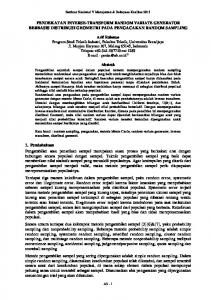
1. Introduction With the proliferation of broadband access to the Internet, video distribution services such as videostreaming or live transmissions are now becoming widely deployed. Since video services involve those users who are heterogeneous in terms of the capacity of access links, the available network bandwidth, the performance of client machines, and the user’s preferences on the perceived video quality, we should introduce mechanisms so that a video stream provided meets user’s environment and preferences. In [1], we proposed mechanisms for video multicast services in which diverse client requests are simultaneously satisfied while network resources are efficiently used. Our mechanisms are developed on the basis of active network technologies where intermediated network nodes, called active nodes, adapts the video rate to the desired level. An active network is a network whose behavior can be dynamically and flexibly tailored to network administrator’s, user’s, or even application’s demands [2]. Each packet passing through a network equipment, called active node, is processed in accordance with a program that is contained in the packet itself or has been preloaded at the node. By introducing programs to active nodes, they can perform highly intelligent packet processing from lower-layer functions such as QoS routing to application-layer functions that manipulate user data in packet payload. In our video multicast mechanisms proposed in [1], to cope with the client-to-client heterogeneity, appropriately chosen active nodes are configured to adapt the rate of an incoming
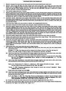
video stream to the desired level by means of video-quality adjustment as illustrated in Fig. 1. In [3], we compared several quality-adjustment mechanisms for real-time MPEG-2 video multicast, namely frame discarding, low-pass, and requantization filters. We proposed algorithms for those quality-adjustment mechanisms to adapt the video traffic to the specified target rate. We conducted several experiments and concluded that the low-pass filter, which provides rate reduction by progressively eliminating high-frequency components of the video signal, is the most effective in terms of suppression of the quality degradation and granularity of the rate adaptation. However, we did not consider several implementation-related issues such as per-packet processing, and limitations in the available memory and the processing capability of the network equipment. To evaluate and verify the practicality and applicability of the video-quality adjustment within a network, we implemented the proposed mechanism on a network processor-based programmable network equipment. In this paper, we show details of high quality video video server
low−quality video
11 00 00 11 00 11 low−bandwidth link
quality adjustment high−quality video high performance 0 client 1 1 0 0 1
low−quality video low performance client
Figure 1: Heterogeneous video multicast
GoP
Sequence layer GoP layer
GoP
I B B P B B P B B
pictures, according to the following formulas:
P B B
l I = − 6.17329 + 59.7498rGi − 112.427rG2i + 111.905rG3i
(1)
l P = − 11.8626 + 85.5488rGi − 159.667rG2i + 139.499rG3i
(2)
GoP : Group of Pictures
Slice
Picture layer
GoP
MB : MacroBlock
lB = Slice Layer MB MB MB MB MB MB MB MB MB
Block Layer
Y1 Y2
Cb
Y3 Y4
Cr
Cb, Cr : Chrominance Blocks Horizontal frequency DCT coefficient
Block
+ 353.265rG3i
, (3)
MB MB MB
Y1~Y4 : Luminance Blocks MacroBlock Layer
− 71.9536 + 360.75rGi − 590.353rG2i
Vertical frequency
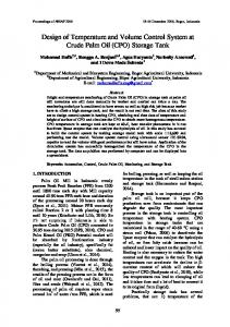
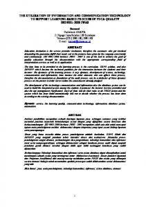
Figure 2: MPEG-2 Video Data the implementation and results of the conducted evaluation experiments. The organization of this paper is as follows. In section 2, we briefly introduce the MPEG-2 coding algorithm, the implemented low-pass filter, and the rate adaptation mechanism. In section 3, we explain the features of the Intel IXP1200 network processor and describe issues related to implementation. We give experimental results and discussion in section 4, and conclude the paper in section 5. 2. Quality Adjustment and Rate Adaptation 2. 1 MPEG-2 Video Coding Algorithm Our low-pass filter is intended for video streams in the MPEG-2 Program Stream format where a video and an audio streams are multiplexed into a single PS stream. Figure 2 shows the hierarchical structure of MPEG-2 video data. The highest layer is called sequence layer. A sequence is constituted by several Group of Pictures (GoPs). A GoP is a sequence of three types of pictures, I (Intra-coded), P (Predictive-coded), and B (Bidirectionally predictive-coded) pictures. A GoP starts with an I picture, followed by several P and B pictures. A picture is composed of 16-pixels height stripes, called slices. All sequence, GoP, picture, and slice layers begin with a 32-bit start code which is used for error recovery and for rewind and fast forward functions. Each slice consists of one or more macroblocks. Each macroblock corresponds to a 16x16 pixel square, and is composed of four 8x8 pixel luminance (Y) blocks and two 8x8 chrominance (Cb, Cr) blocks. Each block is transformed to the frequency domain using discrete cosine transform (DCT). DCT coefficients in a block are in a ascending order of horizontal or vertical frequency. 2.2 Low-Pass Filter To achieve rate reduction, the low-pass filter eliminates appropriately determined number of DCT coefficients from the high frequency ones that constitute a luminance or chrominance block. We call low-pass parameter to the number of DCT coefficients left in each block after quality adjustment. At the beginning of each GoP, initial low-pass parameter values are set independently for I, P and B
where lI , lP , lB are low-pass parameter values for I, P and B pictures, respectively. rGi is the compression ratio for the i -th GoP. For example, with rGi = 0.5 , they are l I = 17 , l P = 14 , l B = 7 . We obtain rGi from the formula below: rGi =
Ti Gi − H i .
(4)
Gi is the predicted size for the i -th GoP in bits which is calculated from the measured size of the (i − 1) -th GoP, g i −1 , using the following formula: Gi =
7 1 Gi −1 + g i −1 , (i ≥ 2, G1 = g 0 ) . 8 8
(5)
H i is the predictor for the total bits used by header data in the i -th GoP, which is derived from the measured header size of (i − 1)-th Gop hi −1 :
H i = hi −1 , (i ≥ 1) .
(6)
Ti is the number of bits allowed to the current GoP, and is calculated from a specified target rate R (bps), the number of pictures in a GoP, N (frames), the frame rate F (fps), and an adjustment value ai : Ti =
R× N − ai − H i . F
(7)
The adjustment value ai is calculated using: ai =
i −1
Tk − f k 5 , k =max (0,i −5 )
∑
(8)
where f k is the size of the filtered k -th GoP. The initial low-pass parameter value is changed dynamically for each of the following intra macroblocks in the GoP, using the following: l j + 1 , rG × oMB − f MB > 0 i j −1 j −1 l j = l j − 1 , rGi × oMB j −1 − f MB j −1 < 0 l , rGi × oMB j −1 − f MB j −1 = 0 j
(9) ,
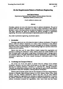
where l j is the low-pass parameter to apply to the j -th macroblock, oMB j −1 is the macroblock size before filtering, and f MB j −1 is the size of the filtered macroblock. Using the above algorithm, the low-pass parameter value for each macroblock is appropriately determined. By eliminating the specified number of DCT coefficients, it is possible to produce a video stream of the desired rate. 3. Implementation of Low-Pass Filter 3.1 IXP1200 Overview We implemented our low-pass filter on a pro-
Intel IXP1200 Chip Data Intel Cache StrongARM Instruction 8KB SA1100 Cache Mini Core 16KB Cache (Linux) 512B SRAM 2MB 32bit 100MHz
SDRAM Unit
SRAM Unit IXBI Unit Scratchpad Memory
Ethernet Ports 64bit ~85MHz
PCI Unit
IX Bus Interface Hash Unit
Micro- Micro- MicroEngine Engine Engine
PCI 32bit Bus 33/66MHz 64bit 100MHz SDRAM For Linux 24MB Shared Memory 8MB
Micro- Micro- MicroEngine Engine Engine
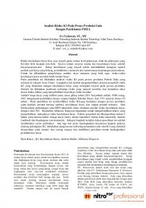
Figure 3: IXP1200 Block Diagram grammable network equipment built on an Intel IXP1200 network processor [4, 5]. The structure of the IXP1200 network processor is illustrated in Figure 3. It has a StrongARM Core processor and six microengines running at 200 MHz. A microengine is a simple RISC processor optimized for packet forwarding and has limitations in the number of registers and executable program size. Each microengine can execute four program threads concurrently, and thus up to 24 threads can be executed in parallel. 24 MByte of the SDRAM is devoted to the StrongARM. 8 MByte of the SDRAM and the SRAM are shared among the StrongARM and the microengines. 3.2 Data Packetization for Video Filtering In order to attain the low-latency and on-the-fly video-quality adjustment, a packet-basis mechanism is indispensable, and thus a video stream should be segmented into a sequence of independent packets. It is reasonable to divide a stream into multiple units of data at start codes. From the sequence layer to the slice layer, we decided to packetize a stream per slice. For example, an MPEG-2 video stream in a profile of MP@ML, i.e., 720x576 pixels and 30 fps, has 36 slices per picture. If it is coded at the coding rate of 8 Mbps, it follows that each packet amounts to 7 Kbits on average. 3.3 Cooperation among Processors With support for multiple execution threads, the IXP1200 has an architecture suited for parallel data processing. We can expect high performance by distributing tasks among the StrongARM, which is a general processor that can perform complex processing, and the microengines, which can execute a high volume of simple processing. To find preferable distribution, we implemented the filtering program on a PC and analyzed the process. For an 8 Mbps stream, we found that 75% of the data is from the block-layer and that 56% of the processing time is spent in processing DCT coefficients. The code executed at the microengines cannot exceed 2048 programming steps and the number of registers is limited, but they are enough to process block-layer data. Consequently, we de-
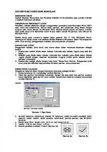
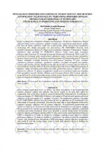
termined to devote the microengines to processing block-layer data. In our implementation, all six microengines are used for video filtering so that we can evaluate the potential capability of the network processor-based video-quality adjustment. 3.4 Communications among Processors For the StrongARM and the microengines to adjust video quality and adapt video rate in a cooperative way, they must communicate with each other and share informations and packet data among them. The video-quality adjustment mechanism we implemented consists of five steps. The current step number is maintained at the SRAM. At the first step, the StrongARM receives a video packet. The packet is first put in the StrongARM’s SDRAM space, but it is immediately copied to the shared area of the SDRAM for data sharing. At the second step, the StrongARM processes headers from sequence to macroblock layers. It then stores informations obtained from headers into the shared memory so that the microengines can use the information in processing block layer. The step moves to the third, and the microengines obtain the block data and required information from the shared memory and apply the quality adjustment algorithm to the blocks. They put back the filtered block to the shared memory. At the fourth step, the StrongARM first reads out the filtered blocks from the shared memory. If they are the last blocks of the given packet, the step proceeds to the fifth and the final. Otherwise the StrongARM processes the next macroblock as at the second step. Finally, at the fifth step, the StrongARM rebuilds a packet and sends it to a network. 4. Evaluation We evaluate our IXP1200-based video-quality adjustment mechanism in terms of the accuracy of rate adaptation, the video quality, and the filtering performance. An MPEG-2 PS stream used for evaluation is coded at the average of 8 Mbps. A video stream of 720x480 pixels and 30 fps, and an audio stream of 192 Kbps are multiplexed into the PS stream. GoP length N is set to 15. We should note here that our implemented system cannot perform the video-quality adjustment at the rate of 8 Mbps, as will be shown later. Thus, especially in evaluating the rate adaptation and the quality, a video stream injected into the IXP1200-based node is smoothed down. 4.1 Accuracy of Rate Adaptation Figure 4 depicts trajectories of rate variation of filtered video streams generated aiming at 2, 4, and 6 Mbps. It is shown that our system can successfully adapt the video traffic to the desired rate. Variations observed in the rate of filtered streams,
8 Mbps 2 Mbps Figure 5: Example of Quality Degradation
Figure 4: Rate Variations of Filtered Stream which sometimes exceed the target rate, are due to the slice-basis packetization and the variable length coding of the MPEG-2. 4.2 Video Quality Variation The low-pass filter achieves rate reduction by eliminating DCT coefficients. As a result, the filtered video loses sharpness and gets blurred. For example, we show an image taken from an original stream of 8 Mbps on the left and one from a stream filtered to 2 Mbps on the right, in Fig. 5. Figure 6 illustrates trajectories of video-quality variation for the same video streams shown in Fig. 4. The video quality is expressed in terms of coding artifact obtained by using the VP2000A of KDDI Media Will Corporation [6]. A higher value of coding artifact indicates that the quality degradation is noticeable as much blockiness, blurriness, and noise. Quality variations, i.e., the shape of the trajectories, of filtered video streams resemble that of an original stream, but the degree of variations becomes higher as the target rate decreases. 4.3 Filtering Performance
Figure 6: Video Quality Variation adaptation mechanism for heterogeneous video multicast on an Intel IXP1200-based network node, and verified its practicality and performance. Our system adapts the video traffic passing through the node to the desired rate by means of video-quality adjustment. It was shown that our system can process the video stream up to 1.35 Mbps. We investigate a further efficient and effective way of videoquality adjustment to improve the performance. References [1] H. Akamine, N. Wakamiya, and H. Miyahara, “Heterogeneous video multicast in an active network,” IEICE Transactions on Communications, vol. E85-B, no. 1, pp. 284–292, January 2002.
We repeatedly examined the quality adaptation while gradually increasing the injection rate by 50 kbps from 0.2 Mbps until the StrongARM begins to fail in receiving video packets. We considered three variants of implementation, they are, (1) only StrongARM is in charge of video-quality adaptation, (2) the StrongARM and one microengine thread cooperate on filtering, and (3) all processors and threads are devoted into filtering. Throughputs attained are 550 Kbps, 350 Kbps, and 1350 Kbps, respectively. Although the highest throughput is not enough for practical purposes, we can see that distributing tasks among processors leads to the higher performance. We should note here that our implementation is not the most suitable. However, this is a good starting point to verify the practicality and usefulness of our idea and we continue improving the performance.
[2] J. Smith, K. Calvert, S. Murphy, H. Orman, and L. Peterson, “Activating networks: A progress report,” IEEE Computer, vol. 32, no. 4, pp. 32– 41, April 1999.
5. Conclusion
[6] KDDI Media Will Corporation, http://www.kmw.co.jp/. (in Japanese).
In this paper, we implemented our video-quality
[3] H. Akamine, K. Nakada, N. Wakamiya, M. Murata, and H. Miyahara, “Implementation and evaluation of video filtering mechanisms for real-time multicast,” Technical Report of the IEICE (NS 2001-50), pp. 13–18, June 2001. [4] Intel Corporation, “Intel IXP1200 network processor family hardware reference manual,” August 2001. [5] T. Spalink, S. Karlin, and L. Peterson, “Evaluating network processors in IP forwarding,” Tech. Rep. TR–626–00, Department of Computer Science, Princeton University, November 2000.