Proceedings of AESAP 2016
13-14 December 2016, Bogor, Indonesia
Design of Temperature and Volume Control System at Crude Palm Oil (CPO) Storage Tank Mohamad Hafiz*,1, Rengga A. Renjani1,2, Agus Haryanto1, Nurbaity Araswati1, and I Dewa Made Subrata1 1)
Department of Mechanical and Biosystem Engineering, Bogor Agricultural University, Indonesia 2) Department of Agricultural Engineering, Stiper Agricultural University, Indonesia E-mail:
[email protected]* Abstract Height and temperature monitoring of Crude Palm Oil (CPO) in storage tank at palm oil mill nowadays are still done manually by worker and carried out twice a day. The monitoring technique is considered to have errors as well as high risk job because worker have to climb a high storage tank, and the result is not real time. The aims of this study are to design control system in heating CPO, obtaining real time data of temperature and height of surface of CPO and circulate the CPO to obtain more homogenous temperature. CPO temperature in storage tank are kept at 40oC, heat transfer phenomena in it can inactivate lipase enzyme that can catalyze the hydrolysis of oil. In this study has succeed to build the control system by making storage model tank with scale 1:18,600 and performing test the model. Volume system control using ultrasound sensor HC-SR04, capable to read the volume with good performance but still have noise. Application of the circulation system has succesfully homogenized the temperature of the CPO in the storage tank. The data acquisition was performed by computer and can be displayed into a spreadsheet. Keywords: Automation, Control, Crude Palm Oil, Monitoring, and Storage Tank
for boiling, pressing, as well as keeping the oil temperature in the tank of sterilization station and storage tank (Hermantoro and Renjani, 2014). Storage tank is an important part of the palm oil mill, because it keeps CPO production save from contaminants that can degrade the quality. The most important process in the storage tank is controlling oil temperature with heating system. CPO temperature in storage tanks that are maintained in the range of 40-60 °C using a steam coil (Pahan, 2006) to deactivate the lipase enzyme that can catalyze the hydrolysis of oil, so free fatty acids increase can be reduced and lower impact on the quality of oil. Heating is also necessary to reduce the water content and the oxygen in the tank. Too high temperatures can accelerate the decline in βcarotene content of which will reduce the quality of CPO (Budiyanto et al., 2010), while low temperatures can lead to clumping of oil and it takes time and a lot of heat to convert it to its original form (liquid). Practically storage tank has several problems, that are: 1) temperature of the
1. INTRODUCTION Palm Oil Mill in Indonesia evenly process Fresh Fruit Bunches (FFB) from 1200 until 1800 tons each day with Mill capacity around 45-90 tons FFB each hour and duration of the processing around 20 hours each day (Syam et al., 2011). Mature FFB commonly called Fraction 2 or 3 with planting time 8 until 10 years (Krisdiarto and Lilik, 2016). So it’s not surprising if Indonesia is able to produce Crude Palm Oil (CPO) amounted to 30.95 tons during 2015 (BPS, 2016). CPO and Palm Kernel Oil (PKO) Potential market will be absorbed by fractionation industry (especially the oil industry), specifically fat (cocoa butter substitute), oleo chemical, margarine and soap (Ulum et al., 2014). The palm oil processing is done through the boiling process (Vincent et al., 2014), threshing, and pressing (Mba et al., 2015), the results of the pressing process are in the form of oil and cake (Owolarafe and Oni, 2011), fiber and seeds (Wahyudi et al., 2012). The processing of palm oil requires vapor steam around 1m3 of water / ton FFB, which is used
95
Proceedings of AESAP 2016
13-14 December 2016, Bogor, Indonesia
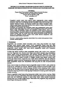
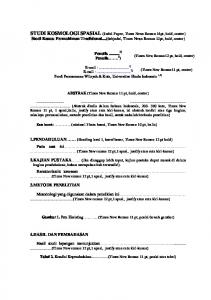
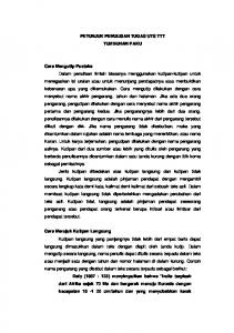
storage tank accumulates just on the bottom of the storage, this is caused by position of steam coil location just in the middle of the tank. 2) measuring the temperature of the storage tank, determination volume amount of CPO in storage are still accommodated and reported by manually (Figure 1). Every day, operator or employee measure to storage tank 2 times a day (morning and late production).
2. MATERIAL AND METHOD The research was conducted from March to May 2016. The design implemented in the field laboratory Siswandhi Soepardjo and laboratory heat and mass transfer, Department of Engineering and Biosystems Engineering, Faculty of Agricultural Technology, Bogor Agricultural University. 2.1 Determination of Design Criteria Design criteria for this research are: 1) Storage downscale method used storage with capacity 500 tons in oil mills with an event ratio of diameter and height. 2) leveling measurement instrument capable of measuring the difference in height certain level and converted as the content volume of CPO. 3) temperature measurement instrument with two criteria: be able to measure the temperature at the bottom or base of the tank CPO, and is capable of measuring temperatures at the top of the CPO. 4) Filling method. Filling used after receiving the data volume of CPO in the storage tank by using a pump, in order to avoid heating when the storage tank is empty. 5) Circulation method. Circulation is based on the temperature difference between the bottom and the top surface of CPO in the storage tank. Circulation is done by using a pump and solenoid valve to regulate the flow path of the higher temperature at the bottom to the top surface. 6) Configuration system and reporting measurement data method. The work configuration is done with the automation control system, which includes automatic data recording. Report system capable of displaying real-time and ongoing data.
Figure 1 Sampling process at storage tank Measurement of oil levelling in the storage tank still use manual method, using a measuring instrument called sounding meters, which has been calibrated (in the form of roll meter or measuring tape). Sounding meter is a device used to determine the height of the oil. Manual measuring process by entering the soundings meters from the top of the storage tank holes to the ends of tanks (tank heights> 10m), readable total height of the oil is converted to oil volume using a calibrated manual book. The results of this measurement is very useful for monitoring the production acquisition, the amount of CPO sold and stored oil. This activity was assessed very wasting time, threatening the safety of workers because it is done in a high place, and the potential occurrence of contamination between the CPO with air, water and impurities in the meter, that can cause decreased quality of CPO. Based on that problems, this study is important because it simulates the design of storage tanks to accommodate the distribution of temperature evenly, automation in the determination of the amount of stock of CPO, the amount of CPO are transferred or received in storage tanks (leveling), than an interface to allow a user to determine the condition and controlling the production of a storage tank system in real time.
2.2 Calibration After the machine and control have made then two kinds measuring instruments calibrated, there are volume and temperature measuring sensor. Calibration of temperature measurement in this study using oil bath which equated to a standard thermometer. Calibration of volume measurement, volume sensor readings on to be adjusted using a ruler to the reference distance and reading the measuring cup chemistry to the reference volume.
96
Proceedings of AESAP 2016
13-14 December 2016, Bogor, Indonesia
= 2670 765/3600 = 742 Wh So, to raise the temperature in one hour required power of heating with 742 W, to make CPO temperature not increasing significantly in short time, then the duration determined around ± 45 minutes, using a 1000 Watt heater. The pumps are used to function as filler and oil circulating to spread the temperature evenly. So to calculate the water horse power is as follows:
3. RESULTS AND DISCUSSION 3.1 Functional Design Generally, storage tanks in oil palm mill have capacity 500 tons or around 560 500 liters, the CPO storage tank structure characteristics are as follows: Max capacity : 571.8 m3 Capacity: 500 tons = 500 000 kg = 561.8 m3 Volume : 560 500 Liters Diameter : 11 000 mm = 11 m Height : 6020 mm = 6.02 m In order to test the design of the temperature control as well as the volume of CPO in the storage tank, the selected prototype tank cylinder with a smaller size (advantages are easily found in the market and flexible in sensor placement) with a volume around 30 liters (scale 1: 18,600) with the specifications: Max capacity : 0.0385m3 Capacity : 0.03 m3 Volume : 30 Liters Diameter : 350 mm = 0.35 m Height: : 400 mm = 0.4 m The use of the heater will be adapted to the needs of heating the CPO with a safe range. Then will be obtained the heater power requirement, and discharge pumps used. If the volume of 0:05 m3 tank, then to raise the temperature from 25 to 55 ° C can be calculated as follows: maverage = ρ V (1) = (913 kg / m3) (0:03 m3) = 27.39 kg qheater = m Cp ΔT (2) = (27.39 kg) (3250 J / kg ° C) (30 ° C) = 2 670 765 A Qa = qheater / 3600 (3)
RP
RSV Fill
MCB1
MCB2
RSV Sir
RH
(4)
Where: WHP = Water Horse Power (kW) = 0.0589 kW = 58.9 W = Specific grafity of fluid (N/m3) = (9.81m2/s) x (905.1 kg/m3) = 8879.03 N/m3 Q = Flow capacity (m3/s) = (2.213 x 10⁻⁵) m3/s = 1.3278 x10⁻³ m3/minute = 0.0797 m3/hour H = head pump (m) = 0.3 m Determination of Net Positive Suction Head Requirement (NPSHR) is known from the values listed on the pump, which is 9 meters. As for calculating the pump shaft or BHP power can be calculated as follows: (5)
MCH AC
P
S Fill
S Sir
H
CH
H
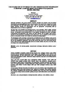
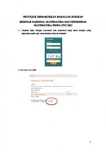
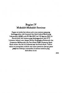
Keterangan: 1. RP 2. RSV Sir 3. RSV Fill 4. RH 5. MCH 6. AC 7. P 8. S Fill 9. S Sir 10. H 11. CH 12. MCB
= Relay Pump = Relay Solenoid Valve Sirkulasi = Relay Solenoid Valve Filling = Relay Heater = Main Contactor Heater = Auxilary Contactor = Pump = Solenoid Valve Filling = Solenoid Valve Sirkulasi = Heater = Contactor Heater = Mini Circuit Breaker
Figure 2 Wirring control diagram
97
Proceedings of AESAP 2016
13-14 December 2016, Bogor, Indonesia
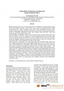
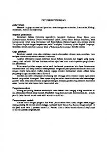
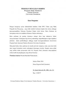
Figure 3 Flow diagram of temperature control and volume storage tank
(6)
Where: BHP η
= Brake horse power (kW) = = pump efficiency (%) =
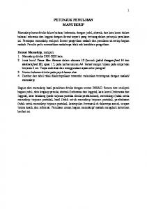
The use of capable the cable to the control system configuration and sensor settings to control the Arduino to use configuration as shown in Figure 2.
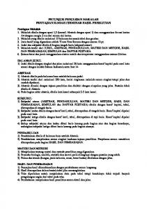
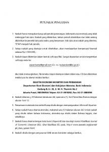
Figure 4 The model of control system design Once the hardware is prepared then proceed with programming the device with some logic programming. Flow diagram of temperature control and CPO storage tank volume is presented in Figure 3. The model of the control system design is shown in Figure 4.
3.2 Manufacturing and Programming Manufacturing is done by providing the tools needed. With the following process: First, the tank is holed at the lower side area to a pipeline, LM35, DS18B20 waterproof, and heater. Second, pipe cut as the required length and connected to the solenoid valve, pump, and the top of the tank. Recently, microcontrollers, electrical panel, solenoid valve and sensor assembled into a single unit.
98
Proceedings of AESAP 2016
13-14 December 2016, Bogor, Indonesia
temperatures, causing oil distribution becomes slow. Similar problem happened by Sastrosayono, (2003) which states that the oil stored at room temperature will freeze and complicate the transport, this is due to the increase number of FFA levels. According to (Tan et al., 2009) saturated FFA generally consists of palmitic (43.7%), and stearic (4.5%), while the unsaturated FFA consist of oleic (40.2%) and linoleic (9, 6%). The temperature required to separate it is more than 31oC or optimal conditions 66.8oC.
Figure 5 Results of tank design
3.4 Sensor Calibration
Result of the machine and cable design obtained in Figure 5, to the arrangement of the control cable volume, temperature and pump arrangements, as shown in Figure 6.
Three sensors are used in the research there are: ultrasound sensor HC-SR 04, temperature sensor LM-35, and temperature sensor DS18B20 waterproof. Ultrasound sensor HC-SR 04 calibration regression addition constants for the results of measuring the sensor close to the reality as shown in Figure 7. It can be seen that the measurement result or real estate and use the sensor is not too far.
Figure 6 Composition of the control circuit 3.3 Pump Test Once all components are manufactured, first step, pump discharge measurements were taken using a measuring cup on CPO storage container. From the measurement results obtained as the pump discharge Table 1. Figure 7 Calibration plotting HC-SR 04
Table 1 Results of measurement of flow rate of the circulation pump
1 2
Discharge (m3/s) 0.0000248 0.00002
Discharge (m3/hour) 0.08928 0.072
3
0.0000216
0.07776
Mean
0.0000221
0.07968
Test
The temperature sensor calibration using standard temperature and oil bath testing machine, in Figure 8 can be seen for sensor LM 35 (Orange dot) can be seen have low sensitivity so that changes in temperature gained enormous. DS18B20 temperature sensor with (Blue dot) is more stable temperature readings so that the temperature accuracy better readability.
Data obtained by charging time test to reach 30 liters of oil volume takes 55 minutes and 25 seconds. This happens because there is air in the pump and the oil tank that CPO freeze at the beginning because cold ambient
99
Proceedings of AESAP 2016
13-14 December 2016, Bogor, Indonesia
During the filling phase can be seen that the sensor used in the measurement have noise, which change reads in the tank volume. There are several things that can cause this, including the ability of the sensor itself and the presence of oil splashes so the volume read by sensor is not in the condition it should be. In this mode the relay makes pumps and solenoid 1 function ON, while the solenoid 2 and the heater OFF. Circulation phase can be seen the increase temperature starting from sensor 2 positioned at the top, this happens because of the position sensor 1 is at the bottom of the heater, so that the oil is heated by the heater occur convection and the viscosity become more liquid so the oil rises to the top, while the bottom remains cool and clog. But this obstacle can be overcome because of their mode of circulation as a result of oil in the bottom of the tank that is still cold sucked by the pump, and sent to the top of the CPO that has begun to warm, so that the oil lumps disappear.
Figure 8 Calibration plotting DS18B20 and LM 35 3.5 System Control Test Control system test involves two phases: filling phase and circulation phase for leveling the oil temperature. At the initial filling condition, admittedly quite difficult because of the oil used in the controlled room temperature 23-25oC, white clumps appeared and hold the distribution of oil so to fill the storage about 30 liters volume takes ± 55 minutes as shown in Figure 9.
Figure 9 Plotting between time and height-volume oil in storage at filling mode
100
Proceedings of AESAP 2016
13-14 December 2016, Bogor, Indonesia
Figure 10 Plots between time and temperature at circulation mode Figure 10 shows that in the first 420 seconds is a mode where just the heater ON control be set so that the oil reaches a temperature of 40 °C by turning on the heater. At 420 seconds above it can be seen that the circulation mode ON (Pump ON, Solenoid 2 ON) resulting temperature levelling in the storage tank. At around 700 second we can see the temperature at both temperature sensors have reach set point around 40 °C that make the heater OFF but the circulation still ON to keep temperature all around the storage still same.
free fatty acids and peroxides Numbers Red Palm Oil While Heating (in Indonesian Language). Agritech. Vol. 30, No. 2, Mei 2010. Hermantoro dan Renjani, R.A. (2014). Study Utilization of Reverse Osmosis Water Rejected for Domestic Water Needs and as Boiler Feed Water at palm oil mills (in Indonesian Language). In Proceeding of Indonesian Agricultural Engineering Symposium. Yogyakarta: Universitas Gadjah Mada, pp. 195–199. Available at: https://www.researchgate.net/publication/2 88219753. Krisdiarto, A. W., Lilik S. 2016. Effect of Plantation Damage Road and FFB position in Truck Against Palm Oil Performance (in Indonesian Language). Agritech. Vol. 36, No. 2, Mei 2016. pp.219-225. Mba, O.I., Dumont, M.J. dan Ngadi, M. (2015). Palm oil: Processing, characterization and utilization in the food industry – A review. Food Bioscience, 10, pp.26–41. Owolarafe, O.K. dan Oni, O.A. (2011). Technology in Society Modern mill technology and centralised processing system, an alternative for improving performance of palm oil mills in Abia State, Nigeria. Technology in Society, 33(1–2), pp.12–22. Available at: http://dx.doi.org/10.1016/j.techsoc.2011.0 3.002. Pahan, Iyung. (2006). Complete Guide Palm Agribusiness Management from Upstream to Downstream Up (in Indonesian Language). Jakarta. Penebar Swadaya.
CONCLUSION In the present research has managed to make the control system with the model CPO storage tank using a steamer with a scale of 1: 18,600, through the volume control system using an ultrasound sensor HC-SR04 is capable of reading the height of the oil, but just noise generated is still quite a lot. The heating process the oil is evenly distributed above and below the point of the tank, because it is assisted by the circulation system and supported the accuracy of the sensors around R2 = 0.99. REFERENCES Badan Pusat Statistik. (2016). Production of tree crops by province and type of plant (in Indonesian Language). https://www.bps. go.id/linkTableDinamis/view/id/839. [17 Maret 2016]. Budiyanto, Silsia D, Efendi Z, dan Janika R. (2010). Changes of β-carotene content,
101
Proceedings of AESAP 2016
13-14 December 2016, Bogor, Indonesia
Sastrosayono, S. (2003). The cultivation of oil palm, Practical Tips to Overcome Problems. (in Indonesian Language). Agromedia Pustaka, Jakarta. Syam, A.M., Renjani, R.A. dan Dharmawati, N.D. (2011). Losses Analysis on Seed and Kernel Station Through the Process Approach in Every Equipment (in Indonesian Language). In Proceeding of Indonesian Agricultural Engineering Symposium. Bandung: Padjadjaran University, pp. 134–137. Available at: https://www.researchgate.net/publication/2 88233648. Tan, Choon-hui, Hasanah M.G., Ainie K., Chin-ping T., dan Abdul A.A. 2009. “Extraction and Physicochemical Properties of Low Free Fatty Acid Crude Palm Oil.” Food Chemistry 113(2):645– 50. Available at: http://dx.doi.org/10.1016/j.foodchem.2008 .07.052.
Ulum, M., Suparwati, dan Saipulloh M. (2014). Indonesian Palm Oil Statistic. https://www.bps.go.id/website/pdf_publika si/Statistik-Kelapa-sawit-Indonesia2014.pdf. [17 Maret 2016]. Vincent, C.J., Shamsudin, R. dan Baharuddin, A.S. (2014). Pre-treatment of oil palm fruits: A review. Journal of Food Engineering. 143. pp.123–131. Available at: http://dx.doi.org/10.1016/j.jfoodeng.2014. 06.022. Wahyudi, J., Renjani, R.A. dan Hermantoro. (2012). Losses Oil Analysis on Fiber and Seed Unit Broken in Screw Press with Pressure Variation (in Indonesian Language). In Proceeding of Indonesian Agricultural Engineering Symposium. Denpasar: Udayana University, pp. 13–14. Available at: https://www.researchgate.net/publication/2 88211911.
102