approach based on Elevation Map using a Dense Stereo-Vision system. Once we have the ... Drivable Tunnel Model, whereas collision detection approach is ...
Forward Collision Detection based on Elevation Map from Dense Stereo Sergiu Nedevschi, Andrei Vatavu, Florin Oniga
Abstract—This paper presents a Forward Collision Detection approach based on Elevation Map using a Dense Stereo-Vision system. Once we have the 3D information about the road surface, we extract a set of obstacle delimiters by exploiting the elevation structure through the radial scanning method. Taking in account the car mechanical and movement parameters, we build a 3D model associated to the car trajectory. A robust method was developed to detect when the obstacle delimiters intersect the generated driving tunnel at an unsafe distance.
I. INTRODUCTION
I
T is known that most road accidents are due to human error. 93% of all accidents occur because of driver inattention [1] [2]. The rear-end crashes are involved in 12.9% of these cases. The United Nations Economic Commission for Europe (UNECE) [3] has registered more than 3.6 million accidents in Europe and about 1.9 million accidents in North America. The number of deaths registered in 2004 was nearly 150,000 dead in Europe and 43000 in America According to NHTSA (http://www.nhtsa.dot.gov/), the three major human factors of most road accidents are improper lookout, excessive speed, and inattention [2]. A great part of these accidents can be prevented through the development of effective warning collision systems. Therefore, an Advanced Driver Assistance Systems must have a collision-preventing component, able to advise the driver and provide the relevant information about an imminent impact. The Forward Collision Warning (FCW) systems can be divided into several categories based on the used sensors in the collision detection process (RADAR, LASER, Vision Based etc). Most of FCW uses Laser or Radar sensors [4] [5] situated in front of the car to receive the information about the traffic scene. An example of FCW system using a radar sensor is VORAD VS-400 by Eaton (www.eaton.com). VORAD includes a high frequency forward looking radar that warns drivers of potential obstacle up to 137.16 meters ahead. Other FCW systems are vision based using single camera in order to provide the information like image scale change or image position to detect or track vehicles on the road. An example of a system that uses monocular vision is
Manuscript received 10.06.2008. Sergiu Nedevschi, Andrei Vatavu, Florin Oniga, Technical University of Cluj-Napoca, Computer Science Department, 400020 Cluj-Napoca, ROMANIA (phone: +40-264-401457; fax: +40-264-594491; email: Sergiu.Nedevschi{, Andrei Vatavu, Florin Oniga}@cs.utcluj.ro.
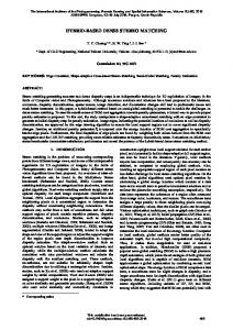
MobilEye-AWS [6]. Most algorithms for FCW are based on determining the relative speed and Time To Collision (TTC) value directly from the position of the object in the image [6] [7] [8] [9]. [10] describes a dynamic situation and threat assessment for collision warning. This paper presents a FCW method based on Elevation Map using a Dense Stereovision System. The proposed algorithm takes in account both the 3D information provided by the Elevation Map module and ego-car parameters such as yaw rate, car speed and steering angle. Our FCW method employs two different 3D models: • The Obstacles Delimiters - are extracted from the Elevation Map and are given as a set of unstructured polygons. We developed a novel approach for the delimiters extraction exploiting the Elevation Map through the radial scanning. • The Drivable Tunnel – is generated based on the car mechanical and movement parameters. The Drivable Tunnel describes a nonconvex polytope and has a variable trajectory depending on the yaw rate, steering angle and car speed [11]. It has a different length at the time t, based on an adjustable warning time and the car speed. We developed a robust method to detect when the obstacle delimiters intersect the generated driving tunnel at an unsafe distance. In the next section, we describe the proposed FCW architecture. Several ways to extract obstacle delimiters are presented in the section 3. Section 4 shows the proposed Drivable Tunnel Model, whereas collision detection approach is presented in the fifth section. The last two sections show the experimental results and conclusion about the FCW we have developed. II. THE FORWARD COLLISION DETECTION ARCHITECTURE We conceived our FCW approach for an urban driving assistance system and developed the forward collision component by extending our Dense Stereo-Based Object Recognition System (DESBOR). A detailed description about the DESBOR system is presented in [12]. The existing parts of the DESBOR system that we have used in our architecture are (Fig. 1): TYZX Hardware Stereo Machine The “TYZX” hardware board performs 3D reconstruction [13]. Coarse Objects are extracted from the dense stereo
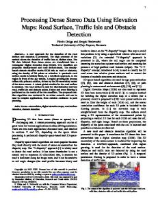
Fig. 2. The car coordinate system.
Fig. 1. Forward Collision Detection Architecture.
information through the grouping process taking into account 3D density variation with the distance [14]. Tracked Objects The coarse object’s position is tracked using Kalman filtering. Tracked objects are described by the position, size and speed [15]. Elevation Map The elevation map represents a description of the scene, derived from the raw dense stereo information. The elevation map cells are classified into road points (drivable points), curb points and object points. The Elevation Map result is used in the Obstacle Delimiters detection [16]. Car parameters such as wheel speed and yaw rate are collected from the onboard sensors at the acquisition time for each frame in the video sequence. The data from the ego motion sensors is received via Controller Area Network (CAN) of the car. The new parts that we have developed for the Forward Collision System are: Object Delimiters The Object Delimiters detection uses the Elevation Map results as the input and generates a set of unstructured polygons approximated with the objects contour. The delimiters are extracted from the Elevation Map through the radial scanning process. We calculate the Obstacle Delimiters for both structured and unstructured objects. Drivable Tunnel The Drivable Tunnel model generation is dependent on the car speed and displacement trajectory.
The 3D model of the tunnel is described by a polyhedron representing a non-convex and structured polytope. Forward Collision Detection The collision detection process is performed between the Drivable Tunnel and Obstacle Delimiters. FCW Output A visual warning is generated based on the detected results from the FCW module. The warning magnitude can be different taking into account the type of the classified points (object points or curb points) and the relative velocity between the Ego-Car and the tracked object from the scene. It must be noted that the car coordinate system coincide with the word coordinate system having its origin on the ground in front of the car (Fig. 2). The position and orientation of the stereo cameras are determined by the absolute extrinsic parameters [17]. The Elevation Map is obtained by fitting a quadric road surface model to the region in front of the ego-car. A detailed description about the Elevation Map detection is presented in [16]. We have extracted the object delimiters based on this model based Elevation Map. III. OBJECT DELIMITERS EXTRACTION In this section, we present the implementation of the obstacle delimiters extraction. A set of steps have been identified for the delimiters extraction: Step 1: The generation of the Top View projection. The Top View image is computed from the Elevation Map. We suppose that obstacles are disjoint in the Top View. Step 2: Object labeling. In this step each object from the Elevation Map is labeled with a unique identifier. Step 3: The contour extraction. Step 4: The polygonal approximation. Given a curve C we will find a polygon that closely approximates C while having as small a number of vertices as possible. We have elaborated many approaches of delimiters extraction. All these methods have in common the 1st, 2nd and 4th step. The 3rd step is different in each case. We have used two main approaches for the contour extraction: a) The contour tracing for a given object – once an
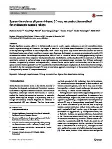
Fig. 3. Border Scanner on Elevation Map (Top View).
object point has been identified, a contour tracing is performed starting from this point and storing each traversed pixel in a list. b) The border scanning – a radial scanning is performed exploiting the elevation map from the Ego Car position. The main difference of this approach is that only the visible part can be scanned. The idea is that the occluded part does not represent relevant information in the delimiters detection process. A disadvantage in the case of the contour tracing approach is that not all the forms of the obstacles can generate a good contour. In some cases, noisy contours can be extracted. There are cases when the same delimiter point can be passed and processed many times. In these cases, segments forming the resulting polygon can include same points. Another problem is when many forms are part of a single object. A single obstacle delimiter cannot be extracted through the simple contour tracing method. Therefore, the border scanning approach has been chose as the extraction method in our system. A. The Border Scanner Algorithm The Border Scanner algorithm performs a radial scanning with a given radial step. The scanning axis moves in the radial direction, having a fixed center at the Ego Car position. The scanning process is made into the limits of two angles Qfrom and Qto. Therefore de delimiters are detected by scanning the interest area in front of the ego vehicle (Fig. 3). Having a radial axis with a Qrad slope,
Q from ≤ Qrad ≤ Qto ,
an object situated on this axis will be reached (the nearest point from the Ego Car). In this way, all subsequent points will be accumulated into Contour List, moving the radial axis in the radial direction. At each radial step we’ll verify if a new object has been reached. If a new label has been found
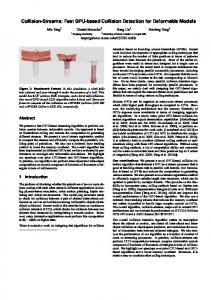
Fig. 4. a) Left image. b) Simple Border Scanner c) Combined Border Scanner.
TABLE I FIXED STEP BORDER SCANNER AND VARIABLE STEP BORDER SCANNER
Number of Frames Detected points The radial step (radians) Points per Frames
Fixed Step Border Scanner 203
Variable Step Border Scanner 203
4529
5733
0.01
0.01
22
28
then the polygonal approximation on the Contour List points is performed. The list will be cleared, and the algorithm will be continued finding a new polygon. Using this method for delimiters extraction, the obtained results are more similar to the real obstacle delimiters from the scene. Another advantage is that the border scanner algorithm resolves the problem of the compound objects presented previously. Therefore, a single delimiter can envelop patches that are more complex. The condition is these patches need to belong to the same object (they have the same label). B. The Border Scanner Algorithm using variable step We need to take in account that the distance between two consecutive detected pixels is greater at the far Z values. Considering the radial step to be constant, the detected pixel density will decrease with the Z distance. The idea is that some important information about the delimiters can be lost at the far distances. A good solution is to use a scanning method with a variable step, thus the radial step should be adapted at once with the distance. If we have found a pixel X at a far distance from the observer, the radial step could be
decreased. Therefore, the radial step varies with the distance. TABLE I contains a case with the results from the Variable Step Border Scanner and Fixed Step Border Scanner for the same driving scene. It can be observed that the number of detected points is greater in the case of Variable Step Border Scanner algorithm, thereby 5733 points, which means 28 detected points per frame in comparison with 22 detected points per frame in the case of Fixed Step Border Scanner algorithm. C. The Combined Border Scanner Algorithm Another aspect is that many relevant objects delimiters may be omitted if we take in account only the first nearest point from the car. Many times, if a radial scanning is performed, the first obstacle from the car can be a curb. In this case, we are interested not only in the curb delimiters but also in the delimiters above the curb or behind the curb. Also we are not interested in the cases of the curbs occluded by the other obstacles. We have elaborated an improved version of the Border Scanner algorithm, which is Combined Border Scanner algorithm. In the Combined Border Scanner algorithm we take in account the obstacle’s nature making a decision based on two types of information “What have we found?” and “What we have to find?” The algorithm consists in two passes: one for the Object delimiters detection, and second for the curb delimiters detection. The Fig. 4 presents the difference between the result of delimiters detection in the case of Simple border Scanner and Combined Border Scanner algorithms. It can be observed that in the case of Combined Border Scanner, the wall’s delimiter is detected in spite of its position behind the curb. IV. THE DRIVABLE TUNNEL The drivable tunnel can be perceived as a safety zone for the vehicle, representing a virtual area around the ego-car trajectory that generated by the mechanical and movement characteristics of the car. The tunnel length must be greater or equal to the car braking distance. At the moment t, the car is moving on a circular arc fC, with radius of curvature fR (Fig. 5). The width and height of the tunnel are W respectively H. The 3D model of the tunnel is described by a polyhedron with the following characteristics: • It is a non-convex polytop • It is a structured model This polyhedron can be decomposed into small cells (Fig. 5). Each cell is a hexahedron with two pairs of parallel faces: Left and Right, Bottom and Top. The Near and Far faces are perpendicular to the car displacement trajectory.
Fig. 5. The Drivable Tunnel.
Because the polygon given representation is a list of vertices, the polygonal clipping can be done by polygon edge-by-edge passing. According to the Cohen-Sutherland Line Clipping algorithm [18], a line is clipped to an upright rectangular window. In our case, the polygonal clipping problem is extended by using as a clipping region the tunnel projection represented in the Fig. 6. The projected tunnel trajectory describes a circular arc with a radius R and the center coordinates C(x0, y0). The two circles with the R1 and R2 radiuses are concentric circles. The Top Boundary describes a line that forms an angle α with the Bottom Boundary; moreover, the α angle is a central angle, which subtends the circular arcs comprised between Bottom Boundary and Top Boundary. Taking into account the tunnel top view from Fig. 6, we define four areas, which will help us to collision detection: • Right Area – is the area, which is delimited from the tunnel by the right edges. • Left Area – is the area that is separated from the tunnel by the left edges, and is located at the left of the tunnel. • Inside Area – is the area from the inside of the tunnel. • Top Area – is the area located above the Tunnel Top Boundary. The collision detection algorithm consists in sequential traversing of polygonal vertices. Three steps are performed for each polygonal vertex: 1. Determining the position of the current vertex: We apply vertex inclusion test to determine if the current vertex is included in one of the four areas. Having a Drivable Tunnel with a radius of curvature fCR, a circle center of coordinates C(xC,yC), and a given vertex P2(x,z) (Fig.7), we define the following constraints: If
the Top Area Else: If
V. COLLISION DETECTION The collision detection problem in the case of models presented above can be related to the polygon clipping algorithms described in [18], which takes as input the vertices of a polygon and returns one or more polygons.
α > α max then the current vertex P2 (x,z) is included in x > x R1 then the current vertex is included in the Right
Area If
x < x L1 then the current vertex is included in the Left
Area If
x L1 ≤ x ≤ x R1 then the current vertex is included in the
Fig. 7. The Drivable Tunnel Geometry
Fig. 6. The Drivable Tunnel – top view.
Inside Area. Where α is the angle formed between the CP1 segment and the OX axis:
α = a tan(
z − Re l 2 Ego x − fCR
)
(1)
The tunnel arcs are intersected by the Top Boundary in TL(xL,zL) and TR(xR,zR) points.
α max
is the central angle,
which subtends the circular arcs comprised between Bottom Boundary and Top Boundary:
α max = a tan(
zR − zL xR − xL
) (2)
AR(xR,zR) is the intersection point between the CP1 segment and the right side of the tunnel. AL(xL,zL) is the result of intersection between the CP1 segment and left side of the tunnel. Both the AR and AL points lie on the CP1 segment. The xR and xL coordinates can be determined by the following relation: For a given xC < 0:
W cos(α ) − fCR 2 W x R = fCR − cos(α ) − fCR 2 For a given xC ≥ 0 : x L = fCR +
(3)
(4)
x L = fCR − fCR +
W cos(α ) 2
(5)
x R = fCR − fCR −
W cos(α ) 2
(6)
2. Determining the edge direction: For each polygonal edge, we assign an edge direction based on the current vertex and previous vertex position. For example if the previous vertex is included in the Right Area, and current vertex is situated inside of the tunnel we have the direction Right_To_Inside. 3. Intersection: Depending on the edge direction, the intersection can be made with one of the polygonal edges (Top Edge, Bottom Edge, Left Edges, and Right Edges) and the result is stored in a collision detection result structure. At each step a delimiter edge may intersect the tunnel only once, twice or never. The main advantage of this approach is that we do not have to traverse all Tunnel edges and intersect them with the current polygonal edge to determine the intersection point. We assume that the intersection of Bottom Edge and Delimiter did not take place, because the Bottom Edge is situated near the Ego-Car, where no 3D points are reconstructed. When delimiter edge intersects the right or left side of the tunnel, the result may be a point located on any left or right chords of the tunnel. In this case, we can adopt a linear approach to search the result by intersecting each chord with the current delimiter. VI. EXPERIMENTAL RESULTS For the experimental purpose, we have tested various scenarios from the urban traffic environment using a 2.66GHz Intel Core 2 Duo Computer with 2GB of RAM. Because our FCW algorithm is performed at the higher level in our architecture, the accuracy of our FCW system depends on 3D information quality provided by the system, obstacle detection, tracking and Elevation Map result. In the Fig. 8 we present the Top View and Free Look images containing two cases of forward collision detection. The delimiters parts being in collision with the Drivable Tunnel are colored in red. Fig. 9 shows a case the relative speed between the two cars is too small. In this situation no messages is generated because detected delimiters are
REFERENCES [1] [2]
[3] [4]
[5]
[6]
[7]
[8] Fig. 8. The Collision Detection: a) and c) are the left image. b) Collision detection - Top View. d) Collision detection - Free Look.
outside the generated tunnel. The system was used in urban scenarios up to a distance of 50m. For the following setup: 0.01 radians for the radial scanning step, a 3 sec horizon for the navigable tunnel and a polygonal approximation error of at most 2 points the average execution time for the FCW module is about 6ms. This performance can be improved by further optimizations.
[9]
[10]
[11]
[12]
[13]
Fig. 9. Collision Detection: a) Left image. b) The generated tunnel (green color) does not include any delimiter
[14]
CONCLUSIONS We have presented a Forward Collision Detection approach based on Elevation Map using a Dense StereoVision system. The proposed algorithm takes in account both the 3D information provided by the Elevation Map module and ego-car parameters such as yaw rate, car speed and steering angle. We have an original method to extract delimiters of detected objects through the Combined Radial Scanning approach and have built a 3D tunnel which length depends on the car relative velocity. The collision warnings are generated when the obstacle delimiters intersect the generated driving tunnel at an unsafe distance.
[15]
[16]
[17]
[18]
J. Treat, Tri-level study of the causes of traffic accidents: Final report volume 1, May 1979. Hendricks and Freedman, The relative frequency of unsafe driving acts in serious traffic crashes, 2001. [Online]. Available: http://www.nhtsa.dot.gov/people/injury/research/UDAshortrpt/UDAs ummtechrept.pdf Economic Commission for Europe, Statistics of Road Traffic Accidents in Europe and North America, Geneva, Vol. LI, 2007. J. D. Woll, “Vorad collision warning radar,” in proceedings of the Radar Conference, Record of the IEEE 1995 International, May 1995, pp. 369 – 372. Z. Lei, W. Jianqiang, and L. Keqiang, “Forward collision warning system based on thasv-ii platform,” in proceedings of Vehicular Electronics and Safety (ICVES), December 2006, pp. 255 – 258. E. Dagan, O. Mano, G. P. Stein, and A. Shashua, “Forward collision warning with a single camera,” in proceedings of the IEEE Intelligent Vehicles Symposium, June 2004, pp. 37–42. R. J. Kiefer, Forward collision warning requirements project final report - task 1, National Technical Information Service, Springfield, Virginia, January 2003. D. J. Lee, R. W. Beard, P. C. Merrell, and P. Zhan, “See and avoidance behaviors for autonomous navigation,” in proceedings of SPIE Optics East, Robotics Technologies and Architectures, Mobile Robot XVII, vol. 5609-05, Philadelphia, PA, USA, October 25-28 2004. I. Gat, M. Benady, and A. Shashua, “A monocular vision advance warning system for the automotive aftermarket”, in proceedings of SAE 2005 World Congress & Exhibition, Detroit, MI, USA, April 2005, pp. 1-8. A. Polychronopoulos, M. Tsogas, A. Amditis, U. Scheunert, L. Andreone, and F. Tango, “Dynamic situation and threat assessment for collision warning systems: The euclide approach,” in proceedings of the IEEE Intelligent Vehicles Symposium, Parma, Italy, June 14-17, 2004, pp. 636–641. S. Ruhl, M. Grinberg, and D. Willersinn, “Empirical evaluation of motion models for a side-looking driver assistance system,” in Proceedings of the 5th International Workshop on Intelligent Transportation (WIT 2008), Hamburg, March 2008, pp. 19-24. S. Nedevschi, R. Danescu, T. Marita, F. Oniga, C. Pocol, S. Sobol, C. Tomiuc, C. Vancea, M. M. Meinecke, T. Graf, T. B. To, M. A. Obojski, "A Sensor for Urban Driving Assistance Systems Based on Dense Stereovision", Proceedings of Intelligent Vehicles 2007, June 13-15, 2007, Istanbul, pp.278-286 J. I. Woodfill, G. Gordon, and R. Buck, “Tyzx DeepSea High Speed Stereo Vision System”, in Proceedings of the IEEE Computer Society Workshop on Real Time 3-D Sensors and Their Use, Conference on Computer Vision and Pattern Recognition, June 27-02, 2004, pp. 4141. C. Pocol, S. Nedevschi, “Obstacle Detection for Mobile Robots, Using Dense Stereo Reconstruction,” in proceedings of the IEEE International Conference on Intelligent Computer Communication and Processing (ICCP’07), Cluj-Napoca, Romania, September 6-8, 2007, pp. 127-132. S. Nedevschi, R. Danescu, T. Marita, F. Oniga, C. Pocol, S. Sobol, T. Graf, R. Schmidt, "Driving Environment Perception Using Stereovision", in Proceedings of IEEE Intelligent Vehicles Symposium, (IV2005), June 2005, Las Vegas, USA, pp.331-336. F. Oniga, S. Nedevschi, M. M. Meinecke, and T. B. To, “Road surface and obstacle detection based on elevation maps from dense stereo,” in proceedings of the IEEE Intelligent Transportation Systems Conference, Seattle, WA, 2007, pp. 859–865. T. Marita, F. Oniga, S. Nedevschi, T. Graf, R. Schmidt, "Camera Calibration Method for Far Range Stereovision Sensors Used in Vehicles", in proceedings of the IEEE Intelligent Vehicles Symposium, (IV2006) , June 13-15, 2006, Tokyo, Japan, pp. 356-363. W. Shoaff, Clipping, March 12, 2002. [Online]. Available: http://cs.fit.edu/wds/classes/graphics/Clip/clip.pdf