Four-Dimensional Space Vector PWM Algorithm for Multilevel Four-Leg Converters ´ ´ Oscar L´opez, Jacobo Alvarez, Jes´us Doval-Gandoy, Francisco Freijedo, Alfonso Lago and Carlos M. Pe˜nalver Electronics Technology Department, University of Vigo, Spain ES36210 IECON’08, 10–14 November, Orlando, Florida
Four-leg converters provide an effective neutral connection in three-phase systems with neutral wire. Since they can be considered as four-phase systems, the SVPWM can be carried out with a generic multiphase space vector pulse-width modulation (SVPWM) algorithm. This 4D SVPWM algorithm is the result of applying a recent multilevel multiphase SVPMW technique to four-leg converters. The algorithm was implemented in a low-cost FPGA and it was tested with a five-level inverter.
4D SVPWM Algorithm for Four-Leg Converters
Experimental Results
. . . . . . . . . . . . . . . . . . . . . . . . . . . . Formulation . . . . . . . . . . . . . . . . . . . . . . . . . . . .
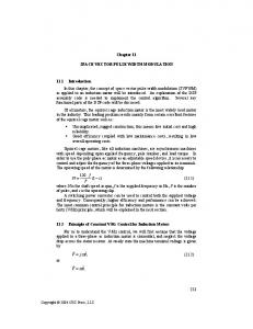
. . . . . . . . . . . . . . . . . . . . . . . . . Simulation results . . . . . . . . . . . . . . . . . . . . . . . . .
Converter
Reference voltage
Leg a +2 +1 0 –1 –2
Leg b
Leg c
+2 +1 0 –1 –2
2
Leg n
+2 +1 0 –1 –2
Voltage (p.u.)
Abstract
+2 +1 0 –1 –2
va
vb
1 vc
0 −1 vn −2 0
0.2
0.4
0.6
0.8
1
0.8
1
0.8
1
0.8
1
0.8
1
Output voltage of leg "a" Voltage (p.u.)
2
Multilevel Multiphase SVPWM Algorithm If P = 4 in generic algorithm . New four-leg SVPWM algorithm: . . . . . . . . . . . . . . . . . . . New generic SVPWM algorithm . . . . . . . . . . . . . . . . . . .
Low computational cost . Good for hardware implementation. For standard multilevel converters: Diode-clamped converters. Flying capacitor converters. Cascaded full-bridge converters. Hybrid converters.
1) 2) 3) 4) 5)
high voltage capability with voltage limited devices; low harmonic distortion; reduced switching losses; increased efficiency; good electromagnetic compatibility.
All results can be summarized in a Table: Cw Ordered vector v ˆf
[000000]
. .Index . . . Terms—Field-programmable . . . . . . . . . . . . . . .gate Multidimensional formulation . . . . . . . . . . . . . . . . . . . . array (FPGA), modulation algorithm, multilevel multiphase converter, space vector pulsewidth modulation (SVPWM).
Multiphase SVPWM is a multidimensional problem that can be formulated I. I NTRODUCTION in a P -dimensional space:
M
OST OF the variable-speed electric drives use three1 2 P T phase machines. Nevertheless, since variable-speed ac r r r r drives include a power electronic converter, the number of 1 than 2three. Major advantages P T of machine phases can be higher s s s s using a multiphase machine instead of a standard three-phase one are [1], [2]:
] ∈R
v = [v , v , . . . , v
where thereliability modulation is: 1) improved and increased law fault tolerance; 2) greater efficiency; +1 pulsations; 3) higher torque density and reducedP torque X 4) lower per phase power handling requirements; vsj tj , 5) enhanced modularity; vr = 6) improved noise characteristics.
j=1 Some recent applications of multiphase systems include hightorque low-speed brushless machines applied to electric vehicle propulsion [3], permanent-magnet motor drives for ship propulsion [4], permanent-magnet motors with low torque pulsation [5], and series-connected two-motor drives with a single inverter supply [6], [7].
Switching vector
where
X
t =1
vˆf a = vf n vˆf b = vf c vˆf c = vf b vˆf n = vf a
..
..
[111111]
vˆf a = vf a vˆf b = vf b vˆf c = vf c vˆf n = vf n
Reference vector
] ∈Z
v = [v , v , . . . , v
Voltage (p.u.)
where Can = [vf a ≥ vf n], Ccn = [vf c ≥ vf n]
Matrix P 1 0 0 0 0 0 0 0 0 1 0 0 0 1 0 0 0 1 0 0 0 1 0 0 0 .. 1 0 0 0 0 0 1 0 0 0 0 0 1 0 0 0 0 0 1 0 0 0 0 0 1
Only twenty four cases are coherent among the sixty four possible combinations with six bits (26 = 64).
Above modulation law can be rewritten in matrix format: 1 1 ... 1 1 Manuscript received February 26, 2007; revised December 11, 2007. This t work was supported by the Spanish of Science and Technology Ministry 1 vunder1 . . . v 1 v Project ENE2006-02930. s2 vr s1University The authors are with the Department of Electronic Technology, 2 t of Vigo, 36310 Vigo, Spain. 2 2 vonline ... v vrfiguresin this=paperarevavailable Color versions of one or more of the s s . 1 2 . at http://ieeexplore.ieee.org. . . . . . Digital Object Identifier 10.1109/TIE.2008.918466 .. . . . . tP +1 0278-0046/$25.00 © 2008 IEEE P P P P vr vs1 vs2 . . . vsP +1 {z } |
The sequence of displaced switching vectors {vd1, vd2, vd3, vd4 vd5} must be extracted from the matrix D, which is calculated from P as: 1 1 1 1 1 1 1 1 1 1 vda vda vda vda vda 0 1 1 1 1 1 2 3 4 5 T b b b b b D= vd1 vd2 vd3 vd4 vd5 = P 0 0 1 1 1 vdc vdc vdc vdc vdc 0 0 0 1 1 1 2 3 4 5 n n n n n 0 0 0 0 1 vd1 vd2 vd3 vd4 vd5
The SVPWM algorithm must: 1. Obtain the coefficient matrix. 2. Solve the system of linear equations.
. . . . . . . . . . . . . . . . Switching vectors and switching times . . . . . . . . . . . . . . . . The final switching sequence is: vs 1 = vi + v d 1
→
t1 = 1 − vˆf a
. . . . . . . . . . . . . . . . . . . . . . . Problem decomposition . . . . . . . . . . . . . . . . . . . . . . .
vs 2 = vi + v d 2
→
t2 = vˆf a − vˆf b
Multilevel SVPWM = Displacement + Two-level SVPWM:
vs 3 = vi + v d 3 vs 4 = vi + v d 4 vs 5 = vi + v d 5
→ → →
t3 = vˆf b − vˆf c t4 = vˆf c − vˆf n t5 = vˆf n
SVPWM SVPWM 2 levels P phases
−1 0.2
0.4
0.6
2
. . . . . . . . . . . . . . . . . . . . Displaced switching sequence . . . . . . . . . . . . . . . . . . . .
N levels P phases
0
Output voltage of leg "c"
. . . . . . . . . . . . . . . . . . . . . . . . . Matrix formulation . . . . . . . . . . . . . . . . . . . . . . . . .
Unknown!
1
0
1 0 −1 −2 0
0.2
0.4
0.6
Output voltage of leg "n" 2
. . . . . . . . . . . . . . . . . . Permutation matrix lookup table: . . . . . . . . . . . . . . . . . .
Any number of levels. Multilevel converters have been extensively studied in a wide variety of applications. Recent industrial applications Any number of phases/legs . Four-leg systems. of multilevel inverters include induction machine drives [10], active rectifiers [11], interface of renewable energy sources to the utility grid [12] and static synchronous compensators [13]. Recently, an initial attempt to integrate a multilevel inverter with a multiphase machine was carried out which demonstrated the advantages of combining both technologies [14]. The space vector pulsewidth modulation (SVPWM) technique offers significant performance benefits and has proved to be very popular in three-phase systems [15]. In [16], a simple P SVPWM algorithm for multilevel three-phase topologies was presented. The method introduced in [17], for threephase inverters with neutral, was later extended to four-wire P topologies in [18]. Recently, in [19], a new SVPWM method for single-phase converters has been presented. With regard to multilevel multiphase SVPWM, an algorithm for a neutral clamped five-phase inverter was proposed in [20]. However, it does not address the extension of the method for a higher P +1 number of levels or phases or its application to other multilevel topologies. In this paper, a generic algorithm to perform the j SVPWM for multiphase inverters is presented. This algorithm, which is valid for the typical multilevel topologies, is the result j=1 of the two main contributions of this paper: the demonstration that a multilevel multiphase modulator can be realized from a two-level multiphase modulator and the development of a new two-level multiphase SVPWM algorithm. Some researchers [21]–[25] have proposed multilevel modulation by using the two-level concept for three phase inverters. A new method for the switching time calculation, where the three-level space vector diagram is divided into six two-level space vector diagrams, is introduced in [21]. However, this 1 include the extension 1 of the method for a number paper does not s P +1 of levels higher than three. In [22], a similar scheme is also pre2 scheme cannot be directly 2 sented for a three-level inverter. This s +1 inverter; nevertheless the principle exapplied to a P multilevel plained in this paper permits making an N -level SVPWM from
Cac = [vf a ≥ vf c], Cbn = [vf b ≥ vf n],
0.6
−2
Voltage (p.u.)
Cab = [vf a ≥ vf b], Cbc = [vf b ≥ vf c],
0.4
2
The permutation matrix P can be obtained from: Cw = [Ccn Cbn Cbc Can Cac Cab]
0.2
Output voltage of leg "b"
Voltage (p.u.)
Multilevel converter technology is based on the synthesis of a voltage waveform from several dc voltage levels. As the number of levels increases, the synthesized output voltage gets more steps and produces a waveform which approaches the reference more accurately. The major advantages of using multilevel inverters are [8], [9]:
0
vi = integ(vr ) = [via, vib, vic, vin]T ∈ Z4 vf = vr − vi = [vf a, vf b, vf c, vf n]T ∈ R4
Óscar López, Member, IEEE, Jacobo Álvarez, Jesús Doval-Gandoy, Member, IEEE, and Francisco D. Freijedo, Member, IEEE
Abstract—In the last few years, interest in multiphase converter technology has increased due to the benefits of using more I than three phases in drive applications. Besides, multilevel converter technology permits the achievement of high power ratings I voltage limited devices. Multilevel multiphase technology with combines the benefits of both technologies, but new modulation techniques Imust be developed in order to take advantage of multilevel multiphase converters. In this paper, a novel space I vector pulsewidth modulation (SVPWM) algorithm for multilevel multiphase voltage source converters is presented. This algorithm I is the result of the two main contributions of this paper: the demonstration I that a multilevel multiphase modulator can be realized from a two-level multiphase modulator, and the development of a new two-level multiphase SVPWM algorithm. The multiphase I SVPWM algorithm presented in this paper can be applied to most multilevel topologies; it has low computational complexity and it is suitable I for hardware implementations. Finally, the algorithm was implemented in a low-cost field-programmable gate array and it was tested in a laboratory with a real prototype using a five-level five-phase inverter.
−1 −2
vs = [vsa, vsb, vsc, vsn]T ∈ Z4
1933
Multilevel Multiphase Space Vector PWM Algorithm
0
vr = [vr a, vr b, vr c, vr n]T ∈ R4
Recently, our research group presented a novel multilevel multiphase SVPWM algorithm: IEEE TRANSACTIONS ON INDUSTRIAL ELECTRONICS, VOL. 55, NO. 5, MAY 2008
1
1 0 −1 −2 0
0.2
0.4
0.6 Time (p.u.)
Switching frequency fs = 10 kHz, fundamental f = 50 Hz. . . . . . . . . . . . . . . . . . . . . . . Hardware implementation . . . . . . . . . . . . . . . . . . . . . . XC3S200 FPGA from Xilinx Target Device: xc3s200 Number of Slice Flip Flops: 2,278 out of 3,840 59% Number of 4 input LUTs: 2,682 out of 3,840 69% Number of occupied Slices: 1,850 out of 1,920 96% Total Number 4 input LUTs: 2,597 out of 3,840 67% Number of bonded IOBs: 91 out of 173 36% IOB Flip Flops: 66 Number of Block RAMs: 0 out of 12 0% Number of MULT18X18s: 0 out of 12 0% Number of GCLKs: 8 out of 8 100% Number of Startups: 1 out of 1 100% Total equivalent gate count for design: 35,861
Leg a:
1 1
1
2
2
2
1
1 1
Leg b:
-2 -1
-1
-1
-1
-1
-1
-1 -1
Leg c:
-1 -1
0
0
0
0
0
-1 -1
Leg n:
1 1
1
1
2
1
1
1 1
. . . . . . . . . . . . . . . . . . . . . . . . . Experimental setup . . . . . . . . . . . . . . . . . . . . . . . . . Inverter Optical link
dSPACE
FPGA
FPGA
Control
SVPWM
Trigger signals
Optical link
dSPACE
dc link
Load
dc link
Inverter
Load
DSPACE DS1103 PPC Controller Board. I XC3S200 FPGA. I Three-phase/four-leg five-level cascaded full bridge inverter. I
. . . . . . . . . . . . . . . . . . . . .Experimental measurements . . . . . . . . . . . . . . . . . . . . .
. . . . . . . . . . . . . . . . . . . . . . . Algorithm lookup table . . . . . . . . . . . . . . . . . . . . . . . A lookup table is obtained if the SVPWM problem is solved in all cases:
integ
Cw
vi = integ(vr ) ∈ ZP vf = vr − v i ∈ RP vdj = f (vf ) vsj = vi + vdj ∈ ZP
Integer part of the vr Fractional part of vr Displaced switching vectors Switching vector sequence
. . . . . . . . . . . . . . . . . . . Two-Level multiphase SVPWM . . . . . . . . . . . . . . . . . . . SVPWM 2 levels P phases
Vector sequence vsj Switching times tj vs1 = vi + [0, 0, 0, 0]T t1 = 1 − vf n vs2 = vi + [0, 0, 0, 1]T t2 = vf n − vf c [000000] vs3 = vi + [0, 0, 1, 1]T t3 = vf c − vf b vs4 = vi + [0, 1, 1, 1]T t4 = vf b − vf a vs5 = vi + [1, 1, 1, 1]T t5 = vf a .. .. .. vs1 = vi + [0, 0, 0, 0]T t1 = 1 − vf a vs2 = vi + [1, 0, 0, 0]T t2 = vf a − vf b [111111] vs3 = vi + [1, 1, 0, 0]T t3 = vf b − vf c vs4 = vi + [1, 1, 1, 0]T t4 = vf c − vf n vs5 = vi + [1, 1, 1, 1]T t5 = vf n
Leg a output voltage
Leg b output voltage
Leg c output voltage
Leg n output voltage
Experimental measurements match with simulation results.
. . . . . . . . . . . . . . . . . . . . . . . . . . Algorithm steps . . . . . . . . . . . . . . . . . . . . . . . . . .
P = f (vf ) ˆ D = PT D ˆ = constant D tj = vˆf j−1 − vˆf j
Permutation matrix → Sort components of vf Displaced switching vectors Upper triangular matrix made with ones Switching times
. . . . . . . . . . . . . . . . . . . . . . . . . Algorithm step list . . . . . . . . . . . . . . . . . . . . . . . . . 1. Calculate normalized reference vr . 2. Decompose the normalized reference into its integer part vi and its fractional part vf . 3. Calculate the permutation matrix P. 4. Calculate the matrix D. 5. Extract the displaced switching vectors vdj from matrix D. 6. Obtain the final switching vectors vsj . 7. Calculate the switching times tj .
1. Calculate vr , vi and vf 2. Calculate Cw 3. See the lookup table Low-order harmonics of phase a
Example 1. vr = [1.39, −1.15, −0, 31, 1.12]T, vi = integ(vr ) = [1, −2, −1, 1]T, vf = vr − vi = [0.39, 0.85, 0.69, 0.12]T 2. Cw = [Ccn Cbn Cbc Can Cac Cab] = [111100] 3. See the lookup table: vs1 = vi + [0, 0, 0, 0]T = [1, −2, −1, 1]T → t1 = 1 − vf b = 0.15 vs2 = vi + [0, 1, 0, 0]T = [1, −1, −1, 1]T → t2 = vf b − vf c = 0.16 vs3 = vi + [0, 1, 1, 0]T = [1, −1, 0, 1]T → t3 = vf c − vf a = 0.30 vs4 = vi + [1, 1, 1, 0]T = [2, −1, 0, 1]T → t4 = vf a − vf n = 0.27 vs5 = vi + [1, 1, 1, 1]T = [2, −1, 0, 2]T → t5 = vf n = 0.12
This work was supported by the Spanish Ministry of Education and Science under the project number ENE2006-02930.
Spectrum of phase a
Low-order harmonic are small . Low THD. High-order harmonics are integer multiples of the switching frequency.
Conclusion A new 4D SVPWM algorithm for multilevel four-leg voltage-source converters is presented: I Derived from a general multilevel multiphase SVPWM technique. I Can be used with the standard multilevel topologies with any number of levels. I Has vey low computational complexity . Suitable for real-time implementation. I Was simulated and implemented in a low-cost FPGA. I Was tested by using a four-leg cascaded full-bridge inverter. http://www.dte.uvigo.es
mailto:
[email protected]