Fourier-based automatic alignment for improved visual cryptography schemes Jacques Machizaud,1,∗ Pierre Chavel,1,2 and Thierry Fournel1 1 Universit´ e de Lyon, F-42023, Saint-Etienne, France CNRS, UMR 5516, Laboratoire Hubert Curien, F-42000, Saint-Etienne, France Universit´ e de Saint-Etienne, Jean-Monnet, F-42000, Saint-Etienne, France 2 Laboratoire
Charles Fabry, UMR 8501 Institut d’Optique, CNRS, Univ Paris Sud 11, 2, Avenue Augustin Fresnel 91127 PALAISEAU CEDEX, France ∗
[email protected]
Abstract: In Visual Cryptography, several images, called “shadow images”, that separately contain no information, are overlapped to reveal a shared secret message. We develop a method to digitally register one printed shadow image acquired by a camera with a purely digital shadow image, stored in memory. Using Fourier techniques derived from Fourier Optics concepts, the idea is to enhance and exploit the quasi periodicity of the shadow images, composed by a random distribution of black and white patterns on a periodic sampling grid. The advantage is to speed up the security control or the access time to the message, in particular in the cases of a small pixel size or of large numbers of pixels. Furthermore, the interest of visual cryptography can be increased by embedding the initial message in two shadow images that do not have identical mathematical supports, making manual registration impractical. Experimental results demonstrate the successful operation of the method, including the possibility to directly project the result onto the printed shadow image. © 2011 Optical Society of America OCIS codes: (100.0100) Image Processing; (100.4998) Pattern recognition, optical security and encryption; (100.2000) Digital image processing; (330.5000) Vision - patterns and recognition
References and links 1. M. Naor and A. Shamir, “Visual cryptography,” Lecture Notes in Computer Science 950(01), 1–12 (1995). 2. O. Kafri and E. Keren, “Encryption of pictures and shapes by random grids,” Opt. Lett. 12(6), 377–379 (1987). 3. C. N. Yang, A. G. Peng, and T. S. Chen, “MTVSS: (M)isalignment (T)olerant (V)isual (S)ecret (S)haring on resolving alignment difficulty,” Signal Process. 89(8), 1602–1624 (2009). 4. F. Liu, C. Wu, and X. Lin, “The alignment problem of visual cryptography schemes,” Designs, Codes and Cryptography 50(2), 215–227 (2009). 5. D. Wang, L. Dong, and X. Li, “Towards Shift Tolerant Visual Secret Sharing Schemes,” Arxiv preprint arXiv:1004.2364.
#151566 - $15.00 USD (C) 2011 OSA
Received 25 Jul 2011; revised 5 Sep 2011; accepted 10 Sep 2011; published 26 Oct 2011 7 November 2011 / Vol. 19, No. 23 / OPTICS EXPRESS 22709
6. W. Yan, D. Jin, and M. Kankanhalli, “Visual cryptography for print and scan applications,” in Proceedings of the 2004 International Symposium on Circuits and Systems 5, Citeseer, 572–575 (2004). 7. J. Weir and W.Q. Yan, “A comprehensive study of visual cryptography,” Transactions on data hiding and multimedia security V 6010, 70–105 (2010). 8. C. N. Yang and T. H. Chung, “A general multi-secret visual cryptography scheme,” Opt. Commun. 283(24), 4949–4960 (2010). 9. H. Yamamoto, Y. Hayasaki, and N. Nishida, “Securing information display by use of visual cryptography,” Opt. Lett. 28(17), 1564–1566 (2003). 10. H. Yamamoto, Y. Hayasaki, and N. Nishida, “Secure information display with limited viewing zone by use of multi-color visual cryptography,” Opt. Express 12(7), 1258–1270 (2004). 11. A. Mar´ echal and M. Francon, “Diffraction, structure des images. Influence de la coh´ erence de la lumi` ere,” Masson, 1959. 12. J. Goodman, “Introduction to Fourier optics,” Roberts & Company Publishers, (2005). 13. L. G. Brown, “A survey of image registration techniques,” ACM Comput. Surv. 24(4), 325–376 (1992). 14. B. Zitova and J. Flusser, “Image registration methods: a survey,” Image and Vision Computing 21(11), 977–1000 (2003). 15. Q. Tian and M. N. Huhns, “Algorithms for subpixel registration,” Computer Vision, Graphics, and Image Processing 35, 220–233 (1986).
1.
Introduction
Visual Cryptography (VC) aims to share a secret message between several so-called shadow images (SI, sometimes named transparencies) in accordance with the initial scheme often referred to as the Naor and Shamir algorithm [1], although essentially the same idea had already been introduced by Kafri and Keren [2]. That algorithm is known to be very effective because no information about the message transmitted whatsoever leaks into any of the SI’s. This differs from the technique known as watermarking (see Appendix A). In VC, all required SI’s need to be present, and need to be overlaid for the message to appear. In addition, the SI’s need to be registered to a high accuracy. The purpose of our contribution is to introduce an automatic procedure to implement SI alignment, which has been pointed out as an obstacle to the development of VC [3–5]. Manual SI alignment is in fact easy for SI’s with small pixel numbers and large pixel size, but angular alignment becomes increasingly difficult as the pixel number increases and the same is true for translation alignment when the pixel size decreases. Computer help is then welcome and can even solve registration problems that would otherwise be completely impractical and prevent tampering with the shadow images. In a VC scheme, each SI is a random distribution of black-and-white subpixels. All subpixels are independent from each other and therefore one SI alone leaks strictly no information. To reveal the message a minimal number of SI’s must be stacked together and duly registered. In this work, we shall consider the case of two digital SI’s, denoted SI1 and SI2 respectively and investigate their registration by automatic means. We use the so-called “print scan” technique [6] where printed images are scanned and then processed by computer. However, in our case only SI1 is printed and SI2 is stored in a secured data base and will never need to be printed. It may nevertheless be projected onto SI1 to provide visual evidence of the result to the user. In Section 2, we briefly review the principles of VC, which have been examined more extensively by Weir and Yan [7], where the possibility of automatic registration in a print scan technique is mentioned. In Section 3, we analyse the Fourier characteristics of the SI’s to support the operation principle of our method for scaling, angular, and translation registration. We show that although the pixels are distributed on a periodic grid, the Fourier transform of SI’s does not show that periodicity. However, as we demonstrate both analytically and visually, the latter can be revealed by simple prepro#151566 - $15.00 USD (C) 2011 OSA
Received 25 Jul 2011; revised 5 Sep 2011; accepted 10 Sep 2011; published 26 Oct 2011 7 November 2011 / Vol. 19, No. 23 / OPTICS EXPRESS 22710
cessing operations. From there, we deduce a registration method, which we describe in Section 4. Experimental evidence of the method, practical and security considerations are discussed in Section 5 before we conclude. 2.
Principles of Visual Cryptography
In VC, the message is encoded into a binary pattern. In each SI, each message pixel is represented by a fixed-size binary pattern, named a share, which therefore consists of subpixels. When SI’s are duly registered, the initial pixel appears as shown in the example below, where 2× 2 subpixel shares are considered. In each share, two of the four subpixels, selected randomly, are black. Figure 1(a) shows all the possible shares in that case. Two identical shares are taken to encode a 0-bit and two complementary shares to encode a 1-bit (see Fig. 1(b)). The random selection of the 0-bit share is repeated for each pixel independently. The central concept in this work is that accurate registration of the SI’s, to a fraction of the subpixel size, is required to obtain a proper result.
Secret Stacked Share 1 Share 2 message share V0
V1
D1
D0
H1
H0
0-bit 1-bit
2w (a)
(b)
Fig. 1. (a) The six types of 2 × 2 shares. The shares are denoted : V0 , V1 and D1 (top left to right), D0 , H1 and H0 (bottom left to right), respectively. (b) An example of the coding of one bit when V0 was selected (at random) for the 0-bit: left to right: the initial bits, the SI1 share (V0 ), the SI2 share, the two SI’s overlaid.
Figure 2 is an illustrative simulation that demonstrates the visualisation of an encoded image using that scheme. As can be seen in Fig. 2(a), nothing appears on only one SI. The second SI is not shown, but its appearance to the observer is exactly the same. As shown in Fig. 2(b), the message is recovered when the two SI’s are perfectly overlaid. The message is still observable in case of a shift of magnitude less than one subpixel (Fig. 2(c)) and disappears beyond (Fig. 2(d)) [3]. VC implies a way to properly register the SI’s which is always arduous when performed by hand [3], once the two SI’s have been printed on transparencies, or one on a transparency and the other on paper or some opaque substrate. This problem, called the alignment problem in literature [4, 8], has so far hampered the deployment of the VC technique. Indeed, the difficulty increases as the number of pixels increases, making angular alignment more demanding. It also increases as the size of the pixels decreases, making linear alignment more demanding. The issue of alignment tolerance has been tackled before [4], but without any attempt at automatically aligning the SI’s. Exploiting tolerance in the manual alignment of one digital SI displayed on a screen and one printed SI, Yamamoto et al. investigated the simultaneous visibility of the decoded image by several observers for black and white visual cryptography [9] and for color visual cryptography [10]. [3, 5] introduced new visual cryptography schemes in order to increase the robustness against shifting one of the SI’s. Very few publications seem to have addressed the important issue of registering visual cryptography images (without
#151566 - $15.00 USD (C) 2011 OSA
Received 25 Jul 2011; revised 5 Sep 2011; accepted 10 Sep 2011; published 26 Oct 2011 7 November 2011 / Vol. 19, No. 23 / OPTICS EXPRESS 22711
(a)
(b)
(c)
(d)
Fig. 2. (a) One single shadow image (SI) composed of 128 × 128 subpixels. Overlay of two SI’s sharing a 64 × 64 secret image for different horizontal shift values: (b) zero subpixel, (c) 0.5 subpixel and (d) 1.5 subpixels.
a mark outside the SI) [7]. In [6], the authors use the Walsh-Hadamard transform to embed a mark in the transform domain for easier registration. In fact, as we shall show, without inserting any mark, the quasi periodic nature of SI’s provides an appropriate solution for image registration based on Fourier transformation and correlation. Indeed, correlation and the associated Fourier techniques have been known since the early days of analog optical image processing [11, 12] for image registration and for pattern recognition outside the specific case of VC, and have again been stressed in [13, 14] for the field of digital imaging. Nevertheless, as we shall see below, their application to VC has some interesting peculiarities. 3. 3.1.
SI registration based on feature detection Hypothesis
Our method uses the Fourier transform in Cartesian coordinates and identifies the object position through the presence of peaks in the Fourier domain. However, preprocessing is required, as will be explained in this section. For VC to be possible, SI1 must lie flat and exempt from distortions. Therefore, only three geometrical transformations may appear during the registration process : translation and rotation in the object plane, and scaling. In the following, we assume the subpixels to be square but the extension to rectangles is straightforward. As explained in the introduction, we consider that SI1 has been printed and that SI2 is stored in computer memory. The first step is to acquire SI1 in digitized form using a proper sanning or photographic technique. Below, we demonstrate that preprocessing the digitized SI1 reveals Fourier domain features provided that the Nyquist-Shannon sampling condition is satisfied. These features can be used for image registration under #151566 - $15.00 USD (C) 2011 OSA
Received 25 Jul 2011; revised 5 Sep 2011; accepted 10 Sep 2011; published 26 Oct 2011 7 November 2011 / Vol. 19, No. 23 / OPTICS EXPRESS 22712
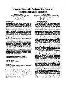
the geometrical transformations of interest (see Fig. (3)).
-1/w -1/(2w) 1/(2w)
(a)
1/w
(b)
Fig. 3. Processing a digitized SI : (a) Edge detection , (b) Amplitude of its Fourier 1 and ± w1 can be seen (black transform. Peaks along the two axes at frequencies ± 2w circles), as well as at the center, where w is the length of the (square) subpixel sides.
3.2.
Features detection
A SI is built on a 2w-pitch square grid composed of four w-side square subpixels. We can expect that the periodicity of the grid may show up in the Fourier plane in spite of the fact that the various types of shares are assigned randomly to each pixel of the SI during the visual cryptography process. However, caution is needed here because each share can be one of the six possible types (see Fig. (1)), which can be described by rectangular functions whose side lengths are precisely either 2w or w. The Fourier 1 . transform of those rectangles is a sinc function with zeroes positioned at multiples of 2w Because the zeroes correspond to the grid spatial frequency, no information about this periodicity is visible in form of peaks in the Fourier space. It is nevertheless possible to reveal these peaks by shifting the sinc function zeroes away. For that, one must change the appearance of a subpixel without changing the periodicity of the grid. This can be done by applying edge detection on the digitized SI1 (see Fig. 3(a)). As seen in Fig. (3), the Fourier plane peaks then appear. As will be explained now, Fourier peaks are enhanced by using a non-symmetrical edge detector as a morphological gradient for which the final edges have thickness t