FPGA-based Implementation of a Polarimetric Radiometer with Digital Beamforming X. Bosch-Lluis, A. Camps, J.F. Marchan-Hernandez, I. Ramos-Perez, R. Prehn, B. Izquierdo, X. Banque, and J. Yeste UPC Campus Nord, Building D3, tel. +34+934017362, E-08034 Barcelona, Spain e-mail:
[email protected] from 25º to 65º. Nowadays, since the signals are sampled and digitally processed, with the computing resources available the instrument is capable of synthesizing two simultaneous beams at two different incidence angles.
Abstract— In [1] a general overview of the PAU system is
provided. This work describes in more detail the implementation of the polarimetric and pseudo-correlation radiometer (PAU-RAD) that measures the four Stokes parameters. I. INTRODUCTION The PAU-RAD is the digital part of the PAU polarimetric and pseudo-correlation radiometer. The design has been implemented in Altera FPGA (Field Programable Gate Array) Stratix EP1S10F780C6E using the VHDL-93 digital description language PAU has a 4x4 element array. Each element has a dualpolarization antenna (horizontal and vertical) and each one is thereafter divided in two using a Wilkinson power splitter. This way, the output signals are proportional to the antenna signal plus or minus the noise added by the resistor of the Wilkinson power splitter. In [2] the receiver topology is described in detail: the input signals are demodulated at an intermediate frequency (IF) of 4.309 MHz and have a 2.6 MHz bandwith. The analog signals are then digitalized at 8 bits and the sampling frequency is 5.745 MHz, higher than the IF, and the “band-pass sampling” technique produces the PAU-RAD input signals to be centered at 0.25 times the digital frequency. In these conditions the PAU-RAD operating frequency must be the same as the sampling frequency, but data will be processed at a much higher frequency. Due to the high number of channels to be processed 64 = 16 receivers x 2 polarizations x 2 channels/polarization signals are multiplexed by a factor 4 and the digital design operates at 22.98 MHz. In this way the necessary logic elements (LE) can be reduced using pipeline and hardware reuse techniques, and then the design becomes smaller and more compact. The basic requirements of PAU-RAD can be summarized as follows: •
I/Q demodulation of 64 input signals,
•
Automatic gain calibration (within ±1 dB), and also ,
•
Automatic phase calibration between receivers (within the range 0 to 2π ).
•
Implementation of a digital beamformer with the 4x4 element array in order to be able to steer the beam up to 20º from boresight in 5º steps. Therefore, in the typical configuration in which the radiometer is pointed at 45º from nadir, the beam can be scanned
•
Computation the four Stokes parameters using correlation techniques.
•
Real time estimation and cancellation of signal’s offsets by a dedicated circuit.
•
Finally, the system must be re-configurable, so that the integration and calibration times, and the intercalibration period may be optimized as a function of the scene and application.
The design has been fit in two Atlera FPGAs Stratix EP1S10F780C6E (without symmetrical charge) at the same time the design has been split in two parts, to implement PAURAD using the VHDL-93 digital description. The first one is called Control Unit and manages the system. The second block of the system is called ALU (Arithmetic-Logic Unit), where the algorithms are implemented. The processing of the digital signals is performed in this block to obtain the four Stokes parameters with the highest achievable accuracy. II.
ANALOG ACQUISITION
The number of bits to use is a trade off by the main beam efficiency of the full array, that cannot be less than 95%, and FPGA resources cost, obtaining that the best effort is for 8 bits per signal [5]. So, the digitalization of the 4 receiver’s channels, one full-polarimetric receiver, is performed with a 2channel 8-bit A/D converter, so a 2-chip structure is used. As it can be observed in Figure 1, the output bus is shared by both chips, that are synchronized and operate at a sampling frequency of 5.745 MHz (CLK). An internal multiplexer determines which digitalized channel is present at the chip outputs, and it is controlled by a signal (I/Q) at 11.490 MHz, so in half-period of CLK each chip will be able to put both channels information in the output bus. Both signals, CLK and I/Q, are supplied by FPGA in order to keep the synchronism through the internal digital process. Taking into account that the differential input signals are centered at 4.309 MHz, the outputs are then centered at 1.436 MHz. In order to expect less than 0.1% out of range samples, (signals are Gaussian stochastic process), to neglect clipping effects over the results and considering that he A/D dynamic range is fixed to 1 V, the signal amplitude must be, in root mean squared voltage (VRMS), 110 mV per channel. The digital
0-7803-9510-7/06/$20.00 (c) 2006 IEEE
output values go from 0 (that corresponds to -0.5V) to 255 (that corresponds to +0.5V), so a 128 offset value is present at the output data.
Figure 3. Hardware reuse sketch
To improve the maximum operating frequency two techniques are used: parallelization, that involves sequential circuits (changes a multiple cycle serial operation to a multiple stage parallel operation), and pipeline, that involves combinational circuits (changes a high delay combinational circuit to multiple low delay circuits with registers). Figure 1. A/D sampling architecture
Figure 2. Output data time diagram
As it is shown in Figure 2, the signals from a full polarimetric receiver enter into the FPGA multiplexed by 4 and, considering that there are 16 channels, our process unit must be capable to ingest and process 367.68 Mbytes per second. In other way, to process this data flux properly design must operate, at less, at 4 times the sampling frequency, i.e. 22.98 MHz III.
PAU-RAD ALU
The ALU processes and obtains the four Stokes parameters from the digital signals that have been acquired. A. Digital Design Techniques PAU-RAD digital design must fit on two FPGAs, using VHDL-93 digital description language. In order to reduce resources and increase possible features, it was carefully designed, and some advanced digital design techniques were implemented. It is possible to take advantage of the signal multiplexing to compact the design using hardware reuse techniques as shown at Figure 3, this increases synchronism complexity because it is necessary to relate sequence signal with the A/C output to know exactly what the ALU is processing at every process stage.
B. Digital Process First of all, a correction must be applied to the input signals to adequate them for the digital processing, this is related to the output of the ADC that gives a binary quantification of the analog signal, but does not have an easy digital interpretation. Subtraction of a fixed value of 128 is applied to all signals to make positive and negative values symmetric and, at the same time, convert the signals into two’s complement. In order to perform the beamforming, the signals must have a zero phase relative error and 0 dB gain error between channels. At this point input signals could have relative phase and gain errors, so they have to be calibrated. Phase errors are related to the fact that the 64 analog receivers do not have a synchronous PLL reference, so the phase is a uniform random variable within the range 0 to 2π radians. Gain errors are introduced by gain variations from each receiver’s chain, so the gain is a Gaussian random variable within the range -1 to +1 dB, because the gains were previously manually adjusted. Therefore signals are centered at 0.25 times the digital frequency, necessary to down-convert them at baseband to obtain I/Q signals. It is possible to down-convert, apply the phase to steer the beam and calibrate in phase and gain the signals performing a single multiplication between the input and the Eq. 1. S ol ( n) =
1
α
e
− j ( wn n +θe
rror
−θbeam )
with n=0,1,2,3... ,
(1)
where: • wn: 0.25 times digital frequency, • 1 : estimated coefficient to calibrate the gain error, α •
θ error : estimated phase to calibrate the phase error, and
•
θbeam : phase value for steering.
0-7803-9510-7/06/$20.00 (c) 2006 IEEE
The next step is to filter I/Q time slots signals, to do this an IIR filter is chosen (Eqn. 2) instead of a FIR one. The reason is that although an IIR could be unstable, it needs a smaller order (less resources) than a FIR one to obtain the same attenuation at a given frequency.
H ( z) =
Figure 4. MDDC sketch
In order to synthesize this in the digital domain, a Multiplexed Digital DownConverter (MDDC) block was developed (Figure 4). The goal of the MDDC is to downconvert and calibrate the signal in a single operation being fully adaptive to new beams or phase/gain errors. The Trigonometric Table (TT) is a set of 16 memory positions that contain all the real possible values of Sol (e.g.: cosine). Taking into account that for one channel Sol repeats its values each 4 time samples, and that the multiplex factor is 4, only 16 values are needed to operate with a full-polarimetric analog receiver. The values of the TT are determined by the Control Unit (CU) as a function of beam steering, phase and gain errors. TT is updated when a new beam is synthesized or the instrument recalibrated. The UC writes the values in the TT using the bus Inbus, the address Position_write and write enable signal EW. COSINUS is the result of the sequential reading of the TT using the synchronism signal sequence. To obtain the SINUS it is the same read sequence with a delay of 4 samples. If the signal would not be multiplexed, then it would be one sample delay. PAU-RAD has 16 MDDCs with their respective TTs in order to process properly data from every full-polarimetric analog receiver. The FPGA resources are saved using RAM for the TT memory positions and dedicated hardware multipliers. To estimate the phase and gains errors the CU has to switch the input analog receiver signal between antenna signal to the correlated noise input, this one is needed to have the same power and phase for each one of the 64 receiver chains, so in this way it could be possible to determine the relative errors between channels and then calibrate them. To calibrate the phase, a dedicated circuit implements a one bit correlation between the signal that is been considered and a reference signal that is assumed to have a zero phase error, these results are given to the CU that applies appropriate algorithms to extract the phase errors from the one bit correlation [4]. For gain, a dedicated circuit computes the power of the signal that is been considered, then in UC this power is related to the power of the reference signal that is assumed to have 0 dB error. Afterwards, the MDDC signals are triangular weighted [1 2 2 1] and added by columns, and then triangular weighted and added by rows, obtaining the desired array illumination. I/Q and time slots are processed separately, so at this point there are 8 beams, 4 for phase signals and 4 for quadrature signals.
0.5 + z −1 + z −2 + 0.5 z −3 1 − 0.5 z −2
(2)
As is shown in Eqn. 3, once the signals are filtered, they are input to a block called pseudo-correlator that multiplies them by pairs of signals. Note that, as in all the flush design signals are time multiplexed, to obtain this results it’s necessary to take into account sequence signal
I ( S A + S R )v * I ( S A − S R )v , I ( S A + S R )h * I ( S A − S R )h and I ( S A + S R )h * I ( S A + SR )v , I ( S A + SR )h * Q( S A + S R )v
(3)
Then the multiplication results are time accumulated in a block called Integrator that adds a new sample to the accumulated value saved in a register to obtain the four Stokes elements. This block can be modified in real time to change the number of accumulated samples, e.g.: integration time. C. Improvements The digital design could be easily modified thanks to the VHDL versatility. This allows to evaluate advanced features and improvements such as the generation of two simultaneous beams in real-time, as implemented in the latest PAU-RAD version, with a marginal design cost because it is only necessary rise the maximum frequency from 22.98 MHz to 45.96 MHz and add some additional registers (note that now TT needs 32 words of 9 bits instead of 16 words), but synchronization difficulty increases. IV.
PAU-RAD CONTROL UNIT The Control Unit (CU) is built on an Altera embedded processor (Nios I) which is implemented in the FPGA. It is a 32 bit processor with 16 bit instructions specially developed to be programmed in C language. So then, the implementation of the CU has been performed in Ansi-C, this way the design has been easier and more versatile. The CU has three main functions: it is both the interface with the ALU and with the external interface of PAU-RAD, and it controls the system operation mode, transmitting to ALU the working state. In addition, it calculates the corrections to be applied to the digital I/Q signals in the calibration mode, and reassigns the values of the 16 TTs depending on the results of the calibration function. The communication with the ALU uses two different registers, depending on the direction: to transmit data from the CU to the ALU and in the opposite direction from the ALU to the CU. The Remote Control is based on a TCP/IP connection with a simple communication protocol that uses 32 bit data packets (4 control bits and 28 information bits). The Remote Control commands make
0-7803-9510-7/06/$20.00 (c) 2006 IEEE
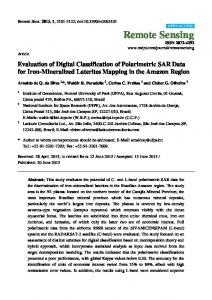
possible actions like connect (activate) or disconnect (deactivate) the device and changing the working parameters (timer, beam angles, static o scanning mode, and time between receivers calibration). The Control Unit has been designed as a Finite State Machine, which is always working in one of the different states according to the radiometer’s operation mode at each moment. LANirq
INIT
Angle B1,B2 or SCAN Mode
New timer
SET_TIME
CAL_MOD
Watchdog (the reset signal comes from TCP/IP connection) with two objectives: checking periodically the status of the connection and the status of CU and resetting if necessary. Second, there is also a Safe Transmission and Execution protocol for remote commands between CU and External Interface that retransmits a command if it has not been correctly received or executed.
WRITE
THOT_TCOL
Intra Calibration Time
V. ACKNOWLEGMENTS This work, conducted as part of the award “Passive Advanced Unit (PAU): A Hybrid L-band Radiometer, GNSSReflectometer and IR-Radiometer for Passive Remote Sensing of the Ocean” made under the European Heads of Research Councils and European Science Foundation EURYI (European Young Investigator) Awards scheme in 2004, was supported by funds from the Participating Organisations of EURYI and the EC Sixth Framework Programme. VI.
NORMAL
Figure 5. Control Unit Finite State Machine
The Block Diagram (Fig. 5) shows the different states of CU and the transitions between them, where: •
continuous arrows: remote command attention,
•
dotted arrows: power-on/ reset sequence, and
•
dashed arrows: Standard sequence.
There is a C main function to implement this State Diagram, and a subroutine to each state, therefore the descriptions of the different states are an explanation of the corresponding subroutine features. INIT is the initialize state, it has two main functions: set the default parameters of the system when resetting and attend the remote commands coming from the external interface. In a reset (or power on) process, the next state is SET_TIME: the CU transmits to the ALU the system timer. In the CAL_MOD state the CU receives, from the ALU, power, I/Q and offset measure that are needed for calculate the signals corrections and receivers calibration. In the next state, WRITE, the TTs are calculated, according to the data obtained in CAL_MOD, and later sent to the ALU. Next, there is a state, THOT_TCOLD, to control the radiometer’s absolute calibration. Finally the NORMAL state is where the system spends more time, the CU is constantly receiving the Stokes Parameters, and sending them to the external interface through the TCP/IP connection. The Standard sequence of states is NORMAL – CAL_MOD – WRITE – NORMAL ...., only modified if a remote command has been received. In that case the system moves to INIT state, or if it is time of a general radiometer’s Calibration, then the system passes through THOT_TCOL state.
REFERENCES
[1] Camps, A., J. F Marchan-Hernandez, I. Ramos-Perez, X. Bosch-Lluis, “New radiometer concepts for ocean remote sensing: Description of the PAU (Passive Advanced Unit)”, Proceedings of the International Geoscience and Remote Sensing Symposium, IGARSS 2006, July 31-August 4 2006, Denver, Colorado. [2] Ramos-Perez, I., X. Bosch-Lluis, A. Camps, J. F. Marchan-Hernandez, R. Prehn, “Design of a compact dual-polarization receiver for pseudo-correlation radiometers at L-band”, Proceedings of the International Geoscience and Remote Sensing Symposium, IGARSS 2006, July 31-August 4 2006, Denver, Colorado. [3] Marchan-Hernandez, J. F. , I. Ramos-Perez, X. Bosch-Lluis, A. Camps, R. Prehn, “FPGA-based implementation of DDM-generator for GPSreflectometry”, Proceedings of the International Geoscience and Remote Sensing Symposium, IGARSS 2006, July 31-August 4 2006, Denver, Colorado. [4] Camps,A., “Aplication of Interferometric Radiometry to Earth Observation”, Ph.D. Thesis, Universitat Politècnica de Catalunya, Barcelona, Spain, 1996 [5] Bosch-Lluis, X., “Disseny i implementació en FPGA d´un radiòmetre polarimètric de pseudo-correlació amb digital beamforming i autocalibració”. Final project, Universitat Politècnica de Catalunya, Barcelona, Spain, 2005.
Finally, as added values, the CU has a couple of redundancy and safety features. First, there is a Remote Reset
0-7803-9510-7/06/$20.00 (c) 2006 IEEE