FPGA based Real-Time Visual Servoing Stefan J¨org, J¨org Langwald and Mathias Nickl German Aerospace Center (DLR) Institute of Robotics and Mechatronics 82234 Weßling, Germany
[email protected]
Abstract Real-time image processing tasks not only require high computing power but also high data bandwidth. Though current processors excel in computing power, memory throughput is still the bottleneck for stream-oriented applications such as low-level image processing tasks. The alternative of special-purpose systems lacks flexibility at a high design effort and long development time. This effort often becomes void by the rapid advance of mainstream computing technology. FPGA technology promises flexibility and the necessary computing performance at affordable design costs. In this paper we describe our approach for a prototype image processing system for robot vision applications, based on FPGA technology. We use a commercially available PCI-Board to implement a typical application based on the Experimental Servicing Satellite (ESS) scenario.
long development time. This effort often becomes void by the rapid advance of mainstream computing technology. Field Programmable Gate Arrays (FPGA) promise flexibility and sufficient computing performance. In the past, several FPGA based systems have been developed and evaluated for image processing, SPLASH-2 [3] and Programmable Active Memories (PAM) [10] being two prominent examples [9]. Those early attempts to create reconfigurable platforms focused on flexibility and scalability, thus yielding costly, general-purpose, multi-FPGA systems with attached memory. For the domain of real-time robot vision, we propose a simpler system consisting of an image acquisition device and a single FPGA processor, integrated on a single board which interfaces to a host. To emphasise its intended use as a dedicated system for pre-processing tasks we label it the intelligent frame grabber. We validate our concept by implementing a typical robot-vision application based on the Experimental Servicing Satellite (ESS) scenario. In
1 Introduction Real-time robot vision tasks such as visual servoing and object tracking require high computational power and data throughput, which often exceed those available on mainstream computer platforms. The first steps in a typical realtime vision application consist of a sequence of low-level algorithms operating on video streams and require only trivial control structures. This makes them ideal for implementation on a specialised system [7]. Therefore, an application can easily be divided into a pre-processing part located on a dedicated subsystem and a high-level part located on a host system. Formerly, we used Datacube MaxVideo pipeline processors for implementing our image processing algorithms [2] [4]. The drawback of such specialised systems is the very restricted set of available operators. To overcome this limitation, we investigated alternative platforms for our pre-processing tasks. Special-purpose systems lack flexibility and come at the cost of much design effort and
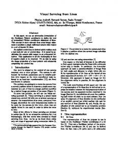
Figure 1. ESS capturing its target section 2 we illustrate the background of the ESS scenario and describe the used image processing methods. Section 3 briefly describes the concept of an intelligent frame grabber. In section 4 we lay out the porting and implementation of each step of the algorithm to the FPGA system. The results of our implementation effort are discussed in section 5.
2 The Benchmark Scenario
3 The Intelligent Frame Grabber
The Experimental Servicing Satellite (ESS) project investigated the problem of servicing non-cooperative satellites in or nearly in a geostationary orbit [8]. The goal was to capture a free-floating satellite by a platform equipped with an intelligent robotic system (Fig. 1). The most critical phases in this scenario are the final approach and capturing of the target. Within the ESS project a test bed was implemented at our institute, where those final phases of vision based tracking and capturing were simulated by two robot manipulators: one playing the role of the target satellite and the other the role of the ESS. Capture is accomplished by entering the target’s apogee engine thruster with a special tool equipped with sensors and a locking mechanism. Because of the stringent size constraints resulting from the integration of the camera into the capture tool, we used a miniature-sized camera with 12mm diameter and a focal length of 4mm. Unfortunately, lenses of this small size suffer from high distortions. For the required visual tracking of the target a very efficient model-based 3D visual tracking algorithm [11] was used, which relies on the robust extraction of image features such as edges. This requires the use of a calibrated sensor yielding rectified images. J¨org et.al [6] transferred this method to industrial assembly applications. Because of the relevance of the algorithm to a wide variety of applications and its typical complexity in terms of robot vision algorithms, we selected it as a prototype implementation for our intelligent frame grabber system.
The concept of an intelligent frame grabber is based on a strictly pipelined architecture: the image acquisition starts a pipeline of subsequent image processing operators. This concept allows modular application design at the operator level by implementing a framework for embedding operators in the pipeline. The high-level part of the application resides on the host and controls the pre-processing part, i.e. the parameters of each operator and the image acquisition, via a host interface. The pre-processor outputs images or more abstract information. The host interface extends the pipeline into the host which requires a tight coupling of host and intelligent frame grabber supported by a proper communication method (see Fig.2).
FPGA
Frame Grabber
Warper
Gradient
Hough
Feature Tracker
3D Tracker
We use a commercially available image processing board with an analogue frame grabber module and a single XILINX Virtex XCV2000E-6 FPGA with one SRAM bank and 6 SDRAM banks. The FPGA operates at 50MHz. As a host we use a Pentium III class Linux system. The image acquisition device is provided as VHDL library by the board manufacturer. For the physical connection of the opHough Threshold
video Warper
NMAC dx Sobel X
gradient magnitude Cordic Units
CPU Visualisation
Video
4 The System Implementation
Object Pose
Accumulator Stream
Hough Acculine_eq : distance muluator line_eq : angle
NMAC dy Sobel Y Image Link
Figure 3. Implementation of the Hough Transform for Lines Control
Figure 2. ESS Application To implement the pre-processing part of the algorithm, the robust extraction of edges, the following operations are necessary: 1) Acquisition of PAL fields with size 384x287 at 50Hz. 2) The image is rectified using a cubic distortion model [12]. 3) The image gradient vector components are computed applying horizontal and vertical Sobel filter masks. 4) The Hough Transform is used to robustly extract all possible edge features of the gradient image. The resulting Hough Accumulator is sent to the CPU based feature tracker (see Fig.2).
erators within the FPGA we designed an image link, which consists of the data itself (e.g. grey-level pixel stream) and three synchronisation signals. The synchronisation signals Pixel Enable, End Of Line and End of Frame implicitly define the current image size. The implementation of each of the three operators of our example scenario is described in the following sections. The processing pipeline starts with the warper operator, followed by the x/y Sobel gradient filtering stage, concluded by the Hough Transform for lines, which involves the calculation of the gradient vector from the x/y gradients (Fig. 3). The immediate result of the Hough Transform is the Hough Accumulator, which is transferred to the
host for further processing, thus marking the end of the preprocessing stage.
4.1 Image Rectification The warper operator for image rectification is based on a sub-pixel accurate coordinate transformation using the following bicubic distortion polynomial: x0 y
0
= a0 + a1 x + a2 y + a3 x2 + a4 xy + a5 y 2
Controller
Source Address integer part (x’,y’)
Latest Line Index
Distorted Image
Input Region Buffer
4 Neighbour Pixels
(1)
Address Generator Source Address fractional part
Bilinear Interpolator
FIFO
P00
The warper structure is shown in Fig. 4. The Address Generator computes the source address for the current output pixel using (1). The polynomial is implemented with 18 multiply and accumulate fixed point operations optimised for the given distortion coefficients. The integer part of the computed source address addresses the Input Region Buffer, which yields the addressed source pixel and its right, lower, and lower right neighbours. Using the fractional address part the grey level of the output pixel is bilinear-interpolated from these four input pixel grey levels. Output Index (x,y)
Image In Pixel Registers
+a6 x3 + a7 x2 y + a8 xy 2 + a9 y 3 = b0 + b1 x + b2 y + b3 x2 + b4 xy + b5 y 2 +b6 x3 + b7 x2 y + b8 xy 2 + b9 y 3
izontal Sobel gradient filters at pixel rate (Fig. 3). The implementation is optimised for the Sobel coefficients. Two registers per line and two FIFOs are required to buffer the input pixels. Figure 5 shows the implementation of the vertical Sobel filter. After an initial delay of two lines and two pixels the filter yields one output pixel per input pixel.
Rectified Image
Figure 4. Image Rectification A straight-forward implementation would require the buffering of the whole input image. An analysis of the camera specific distortion coefficients yields a fixed maximum number of source image lines to be buffered during the generation of one output line. In our case, the required buffer could be reduced to 32 input image lines. Therefore the Input Region Buffer could be placed within the FPGA. The Input Region Buffer is filled by the incoming source pixels and the Controller is notified of the latest completed source line. If all lines needed for the next output line are available, the Controller generates the timing and pixel indices for that line at the full pixel rate of 50 MHz.
4.2 Sobel Gradient Filter For the gradient calculation we implemented two parallel 3x3 neighbourhood operators to realize vertical and hor-
Line Buffer
-
P02
FIFO P10
P22
P 12
-
P20