They hold the promise of assembly, servicing, and repair with a minimal ... is to use a predictive computer graphics system as was successfully demonstrated in the ... the behavior of the remote system will exactly mimic that of the simulation.
Feature-Based Visual Servoing and its Application to Telerobotics Gregory D. Hager,a Gerhard Grunwald,b and Kentaro Toyamaa a Department of Computer Science, P.O. Box 208285 Yale Station, Yale University, New Haven, CT 06520-8285, U.S.A. bGerman Aerospace Research Establishment (DLR), Institute of Robotics and System Dynamics, Munchenerstr. 20, D-82234 Oberpfa�enhofen, Germany Recent advances in visual servoing theory and practice now make it possible to accurately and robustly position a robot manipulator relative to a target. Both the vision and control algorithms are extremely simple, but they must be initialized on task-relevant features in order to be applied. Consequently, they are particularly well-suited to telerobotics systems where an operator can initialize the system but round-trip delay prohibits direct operator feedback during motion. This paper describes the basic theory behind feature-based visual servoing and discusses the issues involved in integrating visual servoing into the ROTEX space teleoperation system.
1. Introduction Automation and robotics are rapidly becoming extremely attractive areas within space technology. They hold the promise of assembly, servicing, and repair with a minimal number of expensive manned missions [7]. However, unlike a factory environment, space operations require the ability to work in an environment which is unstructured. For this reason, some amount of autonomous behavior is necessary to perform complex, diverse tasks. This level of autonomy will rely heavily on vision, depth, force, torque, and tactile sensors, as well as advanced planning and decision capabilities. Unfortunately, our current lack of understanding of sensor data interpretation, robot motion control and arti cial intelligence makes the prospect of complete autonomy for complex tasks unlikely in the near future [2]. One way out of this dilemma is sensor-based telerobotics. In particular, space operation tasks for which telerobotics could play an increasingly large role include inspection, assembly, servicing, and repair [10]. When teleoperating in space, relay satellites and computer networks insert a large delay into round-trip communication. Hence sensor data such as video images cannot be used as direct, real-time feedback by a remote operator. One approach to overcoming this problem is to use a predictive computer graphics system as was successfully demonstrated in the German space robot experiment ROTEX. In ROTEX, the operator handles a control device | a six degree-of-freedom control ball | based on a predictive graphics model of the robot and its environment. The control commands are sent to both the local simulation
and the remote robot. If the simulation is properly calibrated to the real environment, the behavior of the remote system will exactly mimic that of the simulation. Clearly, the crucial problem in this system is to provide an extremely accurate simulation. Teleoperation based on the predictive graphics will fail if the world model does not correspond with reality. This may happen if objects are deformed or damaged (for example, the solar panel of the Hubble Space Telescope), or if an object is freely oating in space. Another disadvantage of relying on a known world model is the need for a precise calibration of the entire operational space. This requirement is di�cult to meet because the mechanics are put under extreme pressure by lifto� and the subsequent temperature di�erences between parts facing the sun and those which are not. One way of lessening the dependence on prior geometric knowledge is to make remote operations sensor-based. Experience has shown that proper use of closed-loop control algorithms operating in orbit can signi cantly enhance the capabilities of the teleoperation system [6]. To date, there has been little progress in the use of visual feedback to support teleoperation. One reason is that most classical work on visual servoing relies heavily on a calibrated hand-eye system. As noted above, maintaining accurate calibration in orbit can be di�cult. A second reason is that most vision algorithms are too complex to execute on hardware that is space-quali ed. In [5], an approach to feature-based visual servoing using closed-loop control was developed. The main advantages of the approach are that it is extremely robust to calibration error and that it uses simple visual features that are computationally simple to track. It can be shown that the accuracy of these visual servoing algorithms is, in fact, independent of calibration error. These properties make the technique well-suited to the teleoperation problem since the operator can choose features and servoing operations using a single static image, and the system can then, without further intervention, autonomously execute the operation with high accuracy and reliability. In this paper we discuss a family of visual servoing techniques, where simple positioning primitives can be easily combined to perform full six degree-of-freedom relative positioning. We then describe some of the issues involved in integrating visual servoing into a teleoperation environment, discuss a preliminary design for such a system, and illustrate its use on an example problem. The remainder of this paper is organized as follows. The next section describes the visual servoing problem and our solution to it. In Section 3, we describe the integration of visual tracking and the telerobotic system, and we discuss the operator interface. In Section 4, we describe our current progress at implementing this system.
2. Feature-Based Visual Tracking and Servoing Vision is an extremely rich and precise mode of sensing. In many ways, it is an ideal candidate for sensor-based motion and manipulation. However, in order to combine vision and robotics, two major problems must be addressed. First, vision problems that involve scene interpretation tend to be extremely di�cult, and most of the vision algorithms used to solve them require specialized hardware in order to operate in real-time. Second, in order to relate visual information to a robot manipulator, the spatial relationship between
(a)
(b)
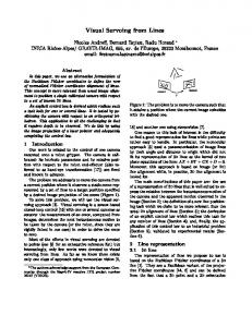
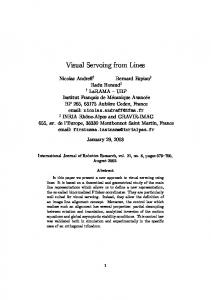
Figure 1. A visual servoing system performing positioning by reducing visual disparity to zero the manipulator and the camera(s) must be known. Determining and maintaining this relationship, the hand-eye calibration, with high accuracy is very di�cult. Here, we describe an approach to visual servoing that eliminates these di�culties. Instead of relying on accurate visual reconstruction, we base motion directly on visual feedback. In humans, this process is called hand-eye coordination. We are attempting to develop similar hand-eye skills for robotic manipulation systems. We hypothesize that a su�ciently large and rich vocabulary of hand-eye skills will dramatically increase the dexterity of robotic systems. For the purposes of this article, hand-eye skills are essentially vision-based feedback control algorithms. These methods use locally de ned visual features, primarily image contours, that can be tracked in real-time by standard workstations or PCs. Corresponding features in two cameras comprise the input to a feedback control system. The feedback control system will provide accurate positioning despite calibration errors provided control gains are chosen to ensure stability.
2.1. Visual Feedback Control
We begin by describing two systems for visual feedback control: one that controls only position, and one that controls both position and orientation. Figure 1 illustrates the underlying principle. We consider a visual servoing system which includes two video cameras, a robot arm, and computers that perform image-processing, low-level control operations, and other interface-related functions. Any attempt to accurately calibrate this system is limited by system modeling errors, mechanical backlash, control inaccuracy, and so forth. Consequently, a system that reconstructs absolute point coordinates using vision and positions the robot based on that information will be extremely imprecise. However, as illustrated in Figures 1(a) and 1(b) the robot manipulator can be positioned extremely accurately relative to the observed target. In (a), the cameras observe the visual disparity �1 and �2 between a point on the manipulator and the corner of the box. We know the following property: zero disparity between the manipulator and the goal in both images
means that they are at the same point in space. This property is true independent of where the cameras are located relative to the robot (More precisely, this statement is true except in con gurations where the goal or robot and the cameras are collinear). Thus, if we have a stable controller to achieve zero visual disparity, we can position accurately, even if the system is badly calibrated. The theory underlying a feedback control algorithm for this problem can be summarized as follows. Suppose that y = f (x) is a mapping from a robot con guration space to an output sensor space, both of dimension n: Given a desired setpoint y�; de ne ey = E (y; y�); where ey approaches zero as y approaches y�. Taking time derivatives,
e_y = JE x;_ (1) where JE = @E (2) @x : If E (�; �) is nonlinear, JE is a function of the system state, x: Thus, if the system state is not directly available, it must be estimated from sensor data. We take u = x_ to be the control input to the system and, presuming JE is full rank, compute u = ?k JE?1 ey (3) where k is a constant set by the designer. If the Jacobian is nonsquare, the control vector is computed by u = ?k JET (JE JET )?1 ey : (4) It is well known that the proper choice of k in discrete time approximations of systems of this form lead to an error, e; that asymptotically approaches zero. Using these concepts, we can construct visual servoing systems to perform di�erent types of positioning and motion by de ning the appropriate image-based error term. The inputs available for de ning errors are contours and xed visual reference points observed in two cameras. The following is a brief review of camera imaging geometry for these features. Camera positions are represented by the frames C1 = (c1; �1) and C2 = (c2; �2): Points and lines in