Wajdi Elhamzi, Taoufik Saidani, Yahia Said, Mohamed Atri. Abstract â Digital Visual Interface (DVI) is gradually being applied to high quality and high resolution ...
International Review on Computers and Software (I.RE.CO.S.), Vol. 8, N. 1 ISSN 1828-6003 January 2013
FPGA Based Real Time Wavelet Video Coding Wajdi Elhamzi, Taoufik Saidani, Yahia Said, Mohamed Atri Abstract – Digital Visual Interface (DVI) is gradually being applied to high quality and high resolution digital video signal transfer between graphic controller and digital display. There have been widespread applications of DVI interface. The valuable digital content, however, is vulnerable to unauthorized access during the transmission. This paper briefly explains the implementation of lifting wavelet algorithms on FPGA and makes a comparative study of their performance. The design utilizes powerful design tool System Generator (SysGen) and Embedded Development Kit (EDK) for hardware-software codesign and integrates the dwt2d codec hardware as a peripheral to the Microblaze 32 bit soft RISC processor with an input from a CMOS camera and output to a DVI display and verified the results video in real time. The proposed algorithm will be implemented in a real time embedded system using Xilinx Video Starter Kit Board- Spartan-3a DSP 3400A Edition. Copyright © 2013 Praise Worthy Prize S.r.l. All rights reserved.
Keywords: Wavelet, FPGA, Vhdl, XSG, Real Time Video Processin
I.
It allows to proces several video streams on the FPGA chip. The number of video streams is limited only by the bottleneck between the FPGA chip and the external memory. The rest of the paper is organised as follows. An overview of the algorithm of wavelet transform are presented in Section 2. Section 3 explains the hardware designing for DWT2Dcore: proposed systems applications and architecture. Real time FPGA implementation results and an overview of the advantages offered with XSG technique are described in Section 4. Finally, concluding remarks are given in Section 5.
Introduction
Wavelet transform has been successfully applied to different fields, ranging from pure mathematics to applied science [1]. Numerous studies, carried out on Wavelet Transform, have proven their advantages in image processing and data compression and have made it a basic encoding technique in recent data compression standards. Purely software implementations of the Discrete Wavelet Transform, however, appear to present a problem when real time systems are required in terms of performance. Therefore, hardware acceleration of the DWT has become a topic of recent research. In the last few years, there has been a growing trend to implement DSP functions in Field Programmable Gate Arrays (FPGAs), which offer a balanced solution in comparison with traditional devices. Although ASICs and DSP chips have been the traditional solution for high performance applications, now the technology and the market are imposing new rules. On one hand, high development costs and time-to-market factors associated with ASICs can be prohibitive for certain applications and, on the other hand, programmable DSP processors can be unable to reach a desired performance due to their sequential-execution architecture. In this context, FPGAs offer a very attractive solution that balance high flexibility, time-to-market, cost and performance. FPGA chips offer high performance with reconfigurability and reusability. A problem is, absent enough of a fast on-chip memory to store intermediate result of graphic algorithms. We need fast access to a huge memory connected with the FPGA by a high speed connection to process a video stream in real time. Today commonly used memory is DDR that offers enough space and speed for graphic algorithms.
II.
The Discrete Wavelet Transform
The Lifting Scheme for Wavelet Transformation was proposed by Sweldens [1]. This method simplified to a great extent the computation of the transform without using the classic techniques of Fourier transformation or complicated operations including convolution which would make the method extremely slow and computationally intensive. The greatest advantage of the Lifting Scheme was its simplicity which allowed the entire evaluation of the wavelet transform in few, easy to understand steps.
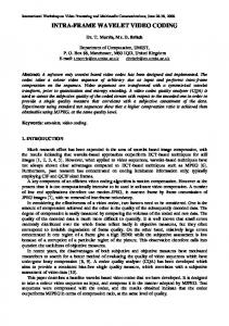
Fig. 1. Lifting scheme forward transform
Manuscript received and revised December 2012, accepted January 2013
243
Copyright © 2013 Praise Worthy Prize S.r.l. - All rights reserved
Wajdi Elhamzi, Taoufik Saidani, Yahia Said, Mohamed Atri
II.3.
With the ever increasing need for high quality data compression techniques Wavelet Transforms using Lifting found instant acceptance among the research community. The JPEG group accepted the Discrete Wavelet Transform using Lifting Scheme as its standard for its JPEG 2000 image compression standards replacing the previously used Discrete Cosine Transform. The basic idea behind the Lifting transform is that we use the correlation in the data to remove redundancy. To this end the transform consists of 3 phases Split, Predict, and Update (Fig. 1). II.1.
Recursive use of the predict stage introduces considerable aliasing in the wavelet coefficients.In this stage the coefficients H-1,k are lifted with the help of the neighboring wavelet coefficients. The 5/3 wavelet filter transform is more suitable lossless data compression adopted in JPEG2000 and 9/7 filter is used in JPEG2000 for lossy compression data. The 5/3 filter has one prediction and one up-dating compared to two predictions and two up-dating for 9/7 filter. The following steps are necessary to get their wavelet coefficients as the following tapes for 5/3 filter: Split the input signal (image) into coefficients at odd and even positions. Perform a predict step, that is the operation given below in (1). Perform up-dating step which is the operation given below in (2):
Split Stage
In this module we first split the data into two sets the odd samples and the even samples. If the samples are indexed beginning with 0, the even set comprises all the samples with an even index and the odd set contains all the samples with an odd index. Let us denote the original set of samples by X0, k. Let the odd and even indexed samples be represented by H-1, k, L-1, k. Our aim here is to decorrelate the signal, i.e. represent the signal with less number of coefficients. So our first step is to simply under sample the signal constituting two groups denoted by the coefficients H-1,k, L-1,k. Now if we can reconstruct the signal X0,k with only H-1,k then we have compressed the signal by half without losing any information. The next step, the predict, will help us find a more elaborate scheme to recover the original samples H-1,k from sub sampled coefficients H-1,k. II.2.
Update Stage
⎡ x ( 2n ) + x ( 2n + 1) ⎤ d ( 2n + 1) = x ( 2n + 1) − ⎢ ⎥ 2 ⎣ ⎦
(1)
⎡ d ( 2n ) + d ( 2n + 1) + 2 ⎤ a ( 2n ) = x ( 2n ) + ⎢ ⎥ 4 ⎣ ⎦
(2)
The lifting based implementation of two levels 2DDWT may be computed using filter banks as shown. The input samples X(n) are passed through two stages of analysis filters. They are first processed by low-pass (h(n)) and highpass (g(n)) horizontal filters and are sub sampled by two. Subsequently, the outputs (L1, H1) are processed by low-pass and high-pass vertical filter. Note that: L1, H1 are the outputs of 1D-DWT; LL1, LH1, HL1 and HH1 one-level decomposition of 2D-DWT.
Predict Stage
So it remains to be seen how we are able to reconstruct the original signal X0,k from the subset H-1,k. If we assume that the data in the original sequence was correlated in some way it would be possible to somehow predict the original sequence from the sub sampled sequence. Assuming that the odd and even samples from the original sequence was correlated then H-1,k = P(0,2k). Since exact prediction is not possible we can encode the difference as:
III. Design Implementation Synthesis and Simulation III.1. Hardware / Software Co-Simulation The hardware/software co-simulation term designates this joint simulation which is to verify that the hardware and software parts of any system function properly together. This includes the simulation of hardware modules, processors and software that the processors execute [10]. The aim of this co-simulation (Fig. 2) is to accelerate the verification of the overall architecture of such an IP ready to be integrated into a reconfigurable platform. We set two types of co-simulations apart, depending on the level at which it occurs: the low-level Cosimulation that involves the system integrator and the VHDL, and the high-level Co-simulation that uses the VHDL with a C written code or the schematic entries done with Matlab and subsequently converted into physical description. Afterwards, we are interested in the latter co-simulation form to verify our Wavelet codec color for the proper interpretation of your figures.
H-1, k = H-1, k − P(H-0,2k) If the signal is correlated then the majority of the wavelets is going to be small consisting of zeroes. So for maximum data compression we want the subsets H-1,k and L-1,k to be maximally correlated Recursively do this for every H-n, k giving raise to L-1,k. Thus the operator P. used for prediction should compute (predict) the odd samples from the even sample. With a good prediction, the two subsets H-1,k and L-1,k yield a more compact representation than the original set H-0,k. The two sets H-1,k and L-1,k are called scaling and wavelet coefficients respectively.
Copyright © 2013 Praise Worthy Prize S.r.l. - All rights reserved
International Review on Computers and Software, Vol. 8, N. 1
244
Wajdi Elhamzi, Taoufik Saidani, Yahia Said, Mohamed Atri
Fig. 2. Xilinx System Generator Flow
The title of the Table must be centered; it has to be 8 pt typed in capital letter. Leave one line space of 10 pt after the Table.
III.3. Hardware Co-Simulation and Real-Time Implementation of the DWT2D-Processor The model (Fig. 4) of high video wavelet processing has three inputs (vs_in, hs_in and data_in) and six outputs. System Generator allows us to predefine the type of bus and signal names and we put the possibility of grouping in a single interface bus the various signals in order to simplify the connections in the EDK tools. The concept for integration of the dwt2d codec algorithm was to create a new subsystem in this model (Fig. 4), titled “DWTcodec”, to implement wavelet transform on the gray data before they were originally routed to Gateway Out blocks. Successful grayscale conversion is a relatively simple system to implement, where the intensity of a pixel is defined as (where R, G and B represent the red, green and blue components, respectively): this model that uses the top level HDL module and its Xilinx blokset for RGB to Gray component. This model can be used for cosimulation. This module is containing 3 multiplier (Mults) and 2 adder (Addsub). The total delay is 4 bars.
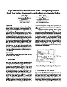
III.2. Proposed Architecture for Lifting Wavelet The proposed architecture performs the forward DWT transform in the column–row fashion. Fig. 3 depicts the overall 2-D DWT architecture, which includes five main components—the Row_dwt,the col_dwt,DPRAM_L and DPRAM_H, the controller_Row and the controller_col: • Row_dwt: a computation block which addresses the application of the filter in the rows lines of the image. • Col_dwt: a computation block which addresses the application of the filter in the lines of the column lines of the image. • controller_col: a controller which generates the write addresses in both DPRAM. • DPRAM_L and DPRAM_H: Two dual port RAM for storing partial coefficients calculated by "Row_dwt", respectively the approximations and details. • controller_Row: a processing block which applies the transform at the columns on the coefficients. Copyright © 2013 Praise Worthy Prize S.r.l. - All rights reserved
International Review on Computers and Software, Vol. 8, N. 1
245
Wajdi Elhamzi, Taoufik Saidani, Yahia Said, Mohamed Atri
Fig. 3. Proposed one-level 2-D DWT architecture -10
z
vso 1 vs_in
-1
In
z
frame _valid _i
vs
vs_out
vs
Delay5 -1
Out
z
Delay 4
frame _valid _o
hs_out
Delay 5
z
R z-1
In
sel
not enableN
Inverter1 z-1
hs
-1
line _valid _i
1 In1
Delay 1
hso
2 hs_in
1 vs_out
hs
ro
Delay 6
do
Delay 2
-1
z
Delay 7
G
Out de _o
2
6 de _out
In2
cout z
Out line _valid _o
Out red _o
-3
Delay4
2 hs_out
dout d0
reset
not Inverter2
3 In3
data
enableOutN
reset
d1
data _in
Black Box
3 red _out
Mux en
out
data_out
enablen_in
ce _out
1 Out1
clk_en_out enablen_out
Black Box1
[a:b] Slice
Counter
go B 3 data _in
-1
In
z
data _i
Delay 3
do1
-1
z
Delay 8
Out green _o
4 green _out
z
-10
Delay6
data bo
e
do2
-1
z
Delay 9
camera design
Out blue _o
5 blue _out
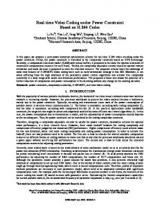
Fig. 7. Diagram of 2D wavelet codec
DWTCODEC
The subsystem shown in Fig. 6 displays the red, green and blue components of the input signal sent to the respective weights, whose outputs are summed together to create the output intensity value. There is one delay block of single latency to allow the weighted blue component to be properly added to the sum of the weighted red and green components. After grayscale conversion, the input signal is prepared for the dwt2d codec algorithm. The DWT2D is designed with vhdl language and insterted in the model with the blackbox technology. For the DWT2D codec, this diagram shows in Fig. 7 that we can use Black Box and include user’s VHDL code or IP core for direct and inverse dwt2d along with Xilinx System Generator’s blocks in the design and generate a synthesizable design which can be implemented using Xilinx ISE’s Project Navigator.
1 Constant System Generator
EDK Processor
Fig. 4. Structure of external model video wavelet processing
Fig. 5. Structure of internal model DWT2D codec
III.4. Synthesis and Simulation When simulation results are correct the implementation steps are done automatically by the tool. In this experiment VHDL code was generated for a Xilinx Spartan-3A DSP 3400A FPGA. On an Intel Pentium 4 running at 3GHz code is generated in less than 2 minutes. Code generation is realised using the instantiation of generic library blocks which are parameterized based on the settings of the designer.
Fig. 6. Diagram of color conversion RGB to gray
Copyright © 2013 Praise Worthy Prize S.r.l. - All rights reserved
International Review on Computers and Software, Vol. 8, N. 1
246
Wajdi Elhamzi, Taoufik Saidani, Yahia Said, Mohamed Atri
XC3SD3400A-4FGG676C FPGA. The wavesimulion is shown in Fig. 8
The synthesized design takes an area of 272 slices in the FPGA, and has a maximum clock frequency of 205.423 MHz. The logic resource consumed by the Dwt2D module along with its other important timing constraints are shown in Table I and Table II. After the co-simulation step the VHDL codes were automatically generated from the System Generator block sets. The VHDL codes were then synthesized using Xilinx ISE 10.1i and targeted for Xilinx Spartan3A DSP 3400 family. The optimization setting is for maximum clock speed. Table I details the resource requirements of the design. Note that in practice, additional blocks are needed for input/output interfaces, and synchronization. The target FPGA chip is Xilinx Spartan 3A DSP XC3SD3400A4FGG676C. During the Simulink-to-FPGA design flow, circuit modeling is built up with Simulink basic blocks and Xilinx specified blocks. Input and output data are combined with MATLAB workspace, which is convenient to convert number format and debug.
IV.
Real Time Implementation Result and Dsicussion IV.1. Exporting the PCore
In order to develop the system either in C or VHDL language, we have to export the pcore into an FPGA design tool such as Xilinx Platform Studio (XPS). This will integrate the pcore which we designed in System Generator into a video processing project. IV.2. FPGA Implementation We used Xilinx Xtreme DSP development board with Spartan 3A DSP Video Starter Kit (VSK)(figure 8). The VSK provides a basic video chain with video input from a static camera and a DVI output. The video chain has a standard RGB interface to connect various video accelerators. The de-serialized input consists of V-Sync, H-Sync and 8 line data bus which serves as the input for the wavelet codec model. Whose signals are described in Table III. The legall wavelet filter is applied in the Camera Processing block on the input signal arriving from the Camera In block. The output signal is Gamma corrected for the output DVI monitor and is driven by Display controller to the DVI output monitor. Video to VFBC and MPMC core helps us to store the image data and buffer them to the output screen.
TABLE I LOGIC RESOURCES CONSUMED BY DWT2D IN XC3SD3400A-4FGG676C USED Available % Number of slices 911 23872 1.13% Number of Slice 1111 47744 1.04% Flip Flops Number of 1331 47744 0.7% 4input LUTs Number of 162 469 19% bonded IOBs Number of 2 24 4% GCLKs
TABLE III BUS SIGNIFICATION OF DVI_VIDEO Red 8bit red component Green 8bit green component Blue 8 bit blue component Vsynch Vertical sychronization Hsynch Horizontal synchronizatio en Valid data
TABLE II TIMING SUMMARY FOR DWT2D IN XC3SD3400A-4FGG676C Minimum Periods 4.868 ns Maximum Frequency 65,167 Mhz
The developed VHDL code has been simulated using ISE Xilinx, synthesized using Xilinx Synthesizer tool (XST) and implemented on Spartan 3A DSP 3400based
Fig. 8. Wave simulation for DWT2D
Copyright © 2013 Praise Worthy Prize S.r.l. - All rights reserved
International Review on Computers and Software, Vol. 8, N. 1
247
Wajdi Elhhamzi, Taoufikk Saidani, Yah hia Said, Mohhamed Atri
codec video, maapping and ssynthesis sysstem. A DVII sign nal is transm mitted into tthe Xilinx XC3SD3400A X A development board. The T visualizatiion of real-tim me video streaam via a CCD D Cam mera is realizzed with an iimage processsing platform m conn nected to a VGA monitor. The PSNR fo or the selectedd images after foorward and iinverse Discrrete Wavelett Tran nsform with 8 bits codingg coefficients are given inn Tab ble IV.
The status reporting annd controllingg of these bllocks are carried out by Miccro Blaze processor p throough Processor Loocal Bus (PL LB). The blocck diagram off the setup is shoown in Fig. 9. 9 In the aboove setup a DVI display show ws the output edge e from the camera. However, for sake of convenience the DWT codec output is verrified on few standard s still images. The input i is fed from a DVI video source s and thee edge is obseerved on the outpuut display screeen. The screeen shot from both input and ouutput is stored and is pressented here. As A a student worrk we devellop the videeo acceleratoor in Matlab/Systeem Generatorr. The accelerrator is compposed as an EDK p-core p that cann be attached to the VSK video v chain, and has an interfface into thee external DDR2 memory throough the Acccess Controlleer and the VFBC V interface. Thhe accelerator can handle four f video streeams from static cameras c and four f streams from the exteernal memory in real time. Each E stream has h a througghput 30MB/s withh a pixel definned by 8-bit inn gray scale.
V.
Conclusion
This T paper hass presented ann efficient arcchitecture of a grap phic accelerattor for wavellet 2d codec which takess advaantage of parrallel logic off FPGAs. We saw how thee Mattlab software and the Sim mulink library y componentss coulld help us to design d a pcore. Then, T we simuulated the desiign and discusssed about thee videeo signals. Thhe pcore was tthen translated d to hardwaree desccription by thee System Geneerator tool of Simulink. S The T pcore waas exported tto XPS and the softwaree funcctions were written w to be able to interact with thee desiign.
IV.3. Result and Discusssion Fig. 10 deescribes the haardware platfoorm of the wavvelet
Fig. 9. Block Diagram of the complete c setup
X deevelopment boardd Fig. 10. Xilinx XC3SD3400A
Copyright © 20013 Praise Worthyy Prize S.r.l. - Alll rights reserved
Internationaal Review on Com mputers and Softw ware, Vol. 8, N. 1
248
Wajdi Elhamzi, Taoufik Saidani, Yahia Said, Mohamed Atri
Yahia Said received the Master‘s Degree in Micro-electronics from Faculty of Science of Monastir, Tunisia in 2010. Since 2011, he has been working as a Research Scientist at the Laboratory of Electronics & Micro-electronics, Faculty of Science of Monastir where he prepares his thesis. His areas of interest include Embedded Processor, Embedded System, Image and Video Processing, and HW/SW Co-design.
References [1]
Tinku Acharya and Ping-Sing Tsai. JPEG2000 Standard for Image Compression: Concepts, algorithms and VLSI architectures. Wiley-Interscience, New York, 2004. [2] ITU-T Recommend. T.800-ISO FCD15444-1: JPEG2000 Image Coding System. International Organization for Standardization, ISO/IEC JTC1 SC29/WG1 (2000). [3] Dhaha Dia, Medien Zeghid, Taoufik Saidani, Mohamed Atri, Belgacem Bouallegue, Mohsen Machhout and Rached Tourki.” Multi level Discrete Wavelet Transform Architecture Design” Proceedings of the World Congress on Engineering 2009 Vol I, London, UK. [4] Agustin Ramirez-Agundis Rafael Gadea-Girones Ricardo Colom-Palero Javier Diaz-Carmona, A wavelet-VQ system for real-time video compression” J Real-Time Image Proc,"Special Issue on: Field Programmable Technology" Springer 2007. [5] T. Saidani , M. Atri ,D. Dia, , and R. Tourki, “Using Xilinx System Generator for Real Time Hardware Co-simulation of Video Processing System”, Electronic Engineering and Computing Technology,.Lecture Notes in Electrical Engineering Springer 2010. [6] S.N.Merchant et A.N.Chandorkar A.D.Darji, R.Bansal. High speed vlsi architecture for 2-d lifting discrete wavelet transform. In Design and Architectures for Signal and [7] Image Processing (DASIP), 2-4 Nov. 2011. [8] Xilinx. XtremeDSP Video Starter Kit – Spartan-3A DSP Edition. [9] Ownby, M.; Mahmoud, W.H.; , "A design methodology for implementing DSP with Xilinx® System Generator for Matlab®System Theory, 2003. Proceedings of the 35th Southeastern Symposium ,". [10] El Bay BOURENNANE,Kamel MESSAOUDI,Maamer TOUIZIA,”Hardware/Software Co-Design with Microblaze Soft Core Processor for the Integer Transform Algorithm Used in the H.264 Encoder”, International Review on Computers and Software (IRECOS),, 5 (N° 3), pp. 348-354, January 2010
Mohamed Atri born in 1971, received his Ph.D. Degree in Micro-electronics from the Science Faculty of Monastir in 2001. He is currently a member of the Laboratory of Electronics & Micro-electronics. His research includes Circuit and System Design, Image processing, Network Communication, IPs and SoCs.
Authors’ information
Wajdi Elhamzi is PhD student at the University of Burgundy (France) and Monastir (Tunisia) since 2009. He obtained his Master degree in electronics in 2008 from Monastir University. He is involved in FPGA based hardware implementation of image processing algorithm, and currently focus on motion estimation for real-time video coding.
Taoufik Saidani is PhD student at the Monastir (Tunisia) since 2008. He obtained his Master degree in electronics in 2007 from Monastir University. He is involved in FPGA based hardware implementation of image processing algorithm, and currently focus on video and JPEG 2000 standard for real-time video coding.
Copyright © 2013 Praise Worthy Prize S.r.l. - All rights reserved
International Review on Computers and Software, Vol. 8, N. 1
249