International Journal of Power Electronics and Drive System (IJPEDS) Vol. 5, No. 3, February 2015, pp. 393~403 ISSN: 2088-8694
393
FPGA Based V/f Control of Three Phase Induction Motor Drives Integrating Super-Lift Luo Converter P.Elangovan*, Nalin Kant Mohanty** * Departement of Electrical and Electronics Engineering, S.K.P. Engineering College, Anna University ** Departement of Electrical and Electronics Engineering, Sri Venkateswara College of Engineering, Anna University
Article Info
ABSTRACT
Article history:
The significance of Elementary Positive Output Super-Lift Luo Converter (EPOSLLC) in constant Voltage/Hertz (V/f) controlled Induction Motor (IM) drive is presented. The traditional IM drive which integrates phase controlled rectifier or boost converter in the facade end upshot tribulations like DC link fluctuations and deprived DC link voltage level. To overcome the problem, the conventional DC-DC converter is replaced with Proportional plus Integral (PI) controlled EPOSLLC in the front end of IM drive that produces the DC link voltage in geometric progression. The Voltage Source Inverter (VSI) of the suggested system renders both open loop and closed loop V/f control scheme for IM by feedback regulated Sinusoidal Pulse Width Modulation (SPWM) technique. Simulation and experimental works are conceded and results presented to demonstrate the viability of the proposed approach. Simulation is carried out using MATLAB /SIMULINK software and the experimental setup is built with Field Programmable Gate Array (FPGA) Spartan-6 processor. The anticipated EPOSLLC is found fit for V/f controlled IM drives considering the DC link Voltage, Speed response of IM and Total Harmonic Distorion (THD) in IM current.
Received Dec 5, 2014 Revised Jan 12, 2015 Accepted Jan 21, 2015 Keyword: DC link Voltage EPOSLLC Induction Motor Drives PI controller Total Harmonic Distortion
Copyright © 2015 Institute of Advanced Engineering and Science. All rights reserved.
Corresponding Author: P.Elangovan, Research Scholar & Assistant Professor, Departement of Electrical and Electronics Engineering, S.K.P. Engineering College, Anna University, Tiruvannamalai - 606611 Email:
[email protected]
1.
INTRODUCTION Induction Motors are the Workhorse of the Industry due to its economy of procurement, installation and use. Recent development in the field of Power Electronics planted a wide usage of Induction Motor (IM) in the adjustable speed drives where speed control of the motor is highly required and squirrel cage type of IM is very popular in that case.The basic control involved in variable speed control of IM is application of a variable frequency and variable magnitude of AC voltage to the motor for the attainment of variable speed operation. Many techniques are already introduced to control the IM parameters [1]. However, the method by name constant Voltage/Hertz (V/f) is versatile in use. Further, the V/f technique is classified into open loop and closed loop control. The open loop V/f control of IM presented in [2] use the arrangement of Voltage Source Inverter (VSI) fed IM with source input as DC which fails to discuss the influence of DC link fluctuations in the IM drive due to load disturbance and also the results obtained are ideal. The closed loop V/f control overcomes the problem with the load disturbance that prevails in open loop V/f control of IM. However, the focus on quality DC link voltage for feedback processing is handled by means of a braking circuit [3] which complicates the system design. To introduce the importance of DC link voltage, a new model [4] is developed to utilize the DC link voltage in more efficient way, but the maximum starting current and Total Harmonic Distortion (THD) in stator current of IM are still the barrier factors of practical implementation. Journal homepage: http://iaesjournal.com/online/index.php/IJPEDS
394
ISSN: 2088-8694
In addition, using a DC link capacitor to reduce the THD in stator current of IM is developed [5] but the DC link flickering which is not suitable for feedback controlled system is not eliminated. Instead of adding a passive element to the IM drive system for the purpose of reducing THD, the view turned on to the Pulse Width Modulation (PWM) technique used to generate gate pulse for VSI through which the required variable voltage and variable frequency is attained simultaneously reducing the THD. Among different PWM techniques, the Sinusoidal Pulse Width Modulation (SPWM) [6], [7] is most popular and simple technique applicable for IM drives. In SPWM technique, two signals (a sinusoidal reference signal and a high triangular carrier signal) are compared to provide two statuses (high or low) of output. On the other hand, the ripple content in the DC link voltage destroys the feature of SPWM technique by distorting the output current of VSI. The research work [8] developed a separate DC link voltage control in addition with complex PWM control for back-back converter fed IM drive, but it is not economic for low power IM drives. The influence of DC link fluctuations over the THD of IM current and voltage is very clearly presented in [9] under different working conditions and concluded that the DC fluctuations has an effect on IM parameters. To triumph over the above mentioned drawbacks, the simple DC-DC converters such as boost, buck and buckboost converters were introduced in the façade end of VSI fed IM drive [10], [11]. Using boost converter in IM drives, only twice the input DC is attainable in DC link [12] and hence another factor, DC link voltage level comes into play. An advanced DC-DC converter in Super-Lift Luo converter series [13], [14] by name Elementary Positive Output Super-Lift Luo Converter (EPOSLLC) produce output voltage in geometric progression overcomes the problem that exist in conventional boost converter. However, EPOSLLC is not competent while used with constant conduction duty and the investigation [15] held to control EPOSLLC using PI regulator fails to show improvement of EPOSLLC under load and line variation. This paper implements a superior PI control of EPOSLLC in the front end of both open loop and closed loop V/f controlled IM drives. The proposed IM drive grasp features such as DC link voltage level 1.5 times greater than the conventional boost converter reduced THD in Stator Current of IM, fluctuation free DC link voltage and improved speed regulation of IM.
2.
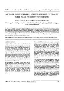
DESIGN OF IMPROVED PI CONTROLLER FOR PROPOSED EPOSLLC The work presented in this paper mainly focus on regulated DC-DC conversion that feeds VSI-IM drive. One of the advanced DC-DC converters from the family of positive output Super-lift Luo series have been chosen for the intended scheme. The positive output Super-lift Luo converter has some sub-series such as Main series, Additional series, Enhanced series, Re-enhanced series and Multiple-enhanced series. The elementary circuit from Main series is implemented for the proposed arrangement. The elementary circuit and equivalent circuit during switch ON and OFF are shown in Figure 1.
(a)
(b)
(c)
Figure 1. (a) Equivalent circuit of EPOSLLC, (b) EPOSLLC during switch ON, (c) EPOSLLC during switch OFF The voltage across C21 is charged to Vi(dc) which is the rectified input to EPOSLLC. The current through the inductor L21 increases with Vi(dc) during switch ON and decreases with – (Vo(dc) - 2Vi(dc)) during switch OFF of EPOSLLC. The average output voltage of EPOSLLC is: Vo(dc) =
2-γ Vi(dc) 1-γ
IJPEDS Vol. 5, No. 3, February 2015 : 393 – 403
(1)
IJPEDS
ISSN: 2088-8694
395
Where, Vo(dc) is the average output voltage of EPOSLLC, Vi(dc) is the input voltage of EPOSLLC and γ is conduction duty. The output current of EPOSLLC is: Io(dc) =
1-γ Ii(dc) 2-γ
(2)
Where, Io(dc) is the average output current of EPOSLLC and Ii(dc) is the input current of EPOSLLC. The voltage transfer gain (G) of EPOSLLC is given by: G=
2-γ 1-γ
(3)
Whereas, the voltage transfer gain of conventional boost converter is: G=
1 1-γ
(4)
On comparing (3) and (4), it is obvious that for the same conduction duty, EPOSLLC produce 1.5 times the voltage transfer that of the conventional boost converter. The control strategy of EPOSLLC using PI regulator is exposed in Figure 2. The error in the actual DC link voltage with respect to the reference DC link voltage is the input to the PI controller.
Figure 2. Control strategy of EPOSLLC The PI controller for anticipated EPOSLLC is designed by finding the appropriate value of proportional gain (Kp) and integral time (Ti). The first step in determining Kp and Ti is to develop the state model of EPOSLLC.The state model of EPOSLLC [16], [17] is determined by assuming the state variables x1 (current flowing through L21), x2 (Voltage across C21) and x3 (Voltage across Co) and input variable u (input voltage of EPOSLLC). Considering negligible input and output resistance of proposed EPOSLLC, the state-space averaging model of EPOSLLC is given by: 1 . 1 x L21 . 1 2 x2 . C21 x3 1 Co
1 1 L21 C21 0
1 L21 x1 L21 0 x2 u C21 x3 1 1 Co Co
(5)
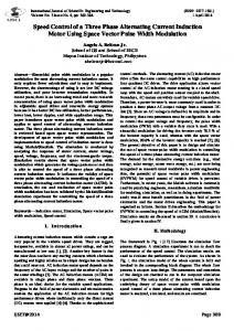
Based on Zeigler – Nichols tuning method [18], Kp and Ti are resolved by applying the step input to the mathematical model (5) of EPOSLLC to attain S – shaped curve and is shown in Figure 3. By drawing a FPGA Based V/f Control of Three Phase Induction Motor Drives Integrating Super-Lift… (P.Elangovan)
396
ISSN: 2088-8694
tangential line to the S-shaped curve gives the constants delay time (L = 0.005s) and time constant (T = 0.015s). From the value of L and T, the Kp (9.36) and Ti (0.016s) are straight away resoluted from Zeigler – Nichols chart. Step Response of EPOSLLC 1 0.9
Response of EPOSLLC
0.8
Tangential Line
0.7 0.6 0.5 0.4
L=0.005s
0.3 0.2
T=0.015s
0.1 0
0
2
4
6
8
10
Time(x(10- 2)s)
Figure 3. S-shaped step response of EPOSLLC
3.
DRIVE TOPOLOGY OF PROPOSED SCHEME AND CALCULATION OF IM PARAMETERS This section explains the two different topologies of IM drive intended and followed by IM parameters calculation. Figure 4 and Figure 5 shows the open loop and closed loop V/f control topology of proposed scheme.
Figure 4. Proposed Scheme with Open Loop V/f Control Topology
Figure 5. Proposed Scheme with Closed Loop V/f Control Topology IJPEDS Vol. 5, No. 3, February 2015 : 393 – 403
IJPEDS
ISSN: 2088-8694
397
Both the scheme presented above incorporates PI controlled EPOSLLC arrangement in the façade end of VSI. The open loop V/f controlled IM drive depicted in Figure 4 process the reference speed that is multiplied with the fixed gain values of modulation index and frequency of the reference sine wave used in SPWM technique for generating gate signals to VSI. Whereas, the closed loop V/f controlled IM drive shown in Figure 5 uses the PI controller for regulating the error in speed of IM via SPWM technique. Apart from the control technique discussed above, the critical parameter estimation of IM is necessary and to assess, the per-phase equivalent circuit of IM in the proposed scheme is designed and shown in Figure 6. In Figure 6, the different parameters of IM are Stator resistance (RS), Stator inductance (XS), Stator phase current (IS), Mutual Inductance (XM), Magnetizing Current (IM), Rotor resistance (RR), Rotor inductance (XR), Rotor current (IR) and Slip (S). For the case presented, the required speed of IM is 1000rpm and the factors such as IM current, Power factor (P.F.) and efficiency (η) are calculated in this section.
Figure 6. Per-Phase Equivalent circuit of Proposed IM Using Kirchoff’s Current law, the primary phase current of IM is specified by, I S = IM + I R
(8)
The expression for magnetizing current (IM) is,
ES jX M
IM =
(9)
Where, ES is internal e.m.f. of IM. The rotor current is, ( )(S )(T ) R R (1 - S )
IR =
(10)
Where, ω is the required speed of IM, in (rps) and T is the torque developed by IM. From (9) & (10), the phase current of IM is determined and the efficiency of IM is given by: η=
PO PO + PL
(11)
Where, PO is power output by IM and PL is the IM losses. The output power and losses of IM is given by: PO =
(1 - S) Plink S 2
(12) 2
PL =3( IS R S + I R R R )
(13)
Where, Plink is the DC link power of the IM drive. From (12), it is understandable that the deprived DC link voltage reduces the magnitude of DC link power and tends to huge drop in output power of IM. This proves that the DC link voltage plays a vital role
FPGA Based V/f Control of Three Phase Induction Motor Drives Integrating Super-Lift… (P.Elangovan)
398
ISSN: 2088-8694
in the efficiency point of IM. The various factors discussed above were calculated for the anticipated scheme of 400V, 50Hz, 1410rpm, 0.5HP, three phase IM and are tabulated in Table 1. Table 1. Calculated Values IM Parameters Motor Current Power Factor Efficiency
Calculated Value 1.736 A 0.926 96 %
4.
SIMULATION WORK AND RESULTS To validate the effectiveness of projected scheme, the Simulink model of ‘EPOSLLC adapted V/f control of IM drive’ is designed and the simulation is conceded using MATLAB 2012a software. The Simulink model is developed for both Open loop and closed loop V/f controlled IM drive with same arrangement of EPOSLLC in the front end and holds invariable simulation circuit parameters which is shown in Table 2. Table 2. Simulation Circuit Parameters Parameter Input AC Supply Induction Motor (IM) Stator Resistance of IM Stator Inductance of IM Rotor Resistance of IM Rotor Inductance of IM Mutual Inductance Inductor Capacitors
Rating 1 phase, 100V, 50Hz 0.5 hp ,3-phase, 50Hz,400V 11.1Ω 18.8mH 12.3Ω 26.7mH 467mH L21 = 2.56mH C21 = 2000µF, Co = 2200µF
The Simulation results such as output voltage of EPOSLLC and line output voltage of VSI remains same for both the simulated Open loop and closed loop V/f controlled IM drive, because the load disturbance affects only the stator current and speed of IM in proposed scheme. To authenticate the preliminary feature of the developed method, the DC link voltage (i.e.) the output voltage of proposed EPOSLLC is shown in Figure 7.
Output Voltage of EPOSLLC
Voltage (V)
400 300 200 100 0
0
0.5
1
1.5
2
2.5
3
Time (s)
Figure 7. Output Voltage of proposed EPOSLLC The above result shows that for 100V rectified input, EPOSLLC produce ripple free 300V DC voltage and verifies the effectiveness of PI controlled EPOSLLC ideally. The output line voltage of VSI in the proposed scheme is shown in Figure 8.
IJPEDS Vol. 5, No. 3, February 2015 : 393 – 403
IJPEDS
ISSN: 2088-8694
399
Line Output Voltage of VSI
Voltage (V)
400 200 0
-200 -400 2.5
2.6
2.7
2.8
2.9
3
Time (s)
Figure 8. Line Output Voltage of VSI in the proposed scheme The speed response of IM for proposed open loop and closed loop V/f controlled IM drive is presented in Figure 9. Speed of IM 1200
1000
1000
Speed (rpm)
Speed (rpm)
Speed of IM 1200
800
Reference Speed Actual Speed
600
800 600
400
400
200
200
0
0
0.5
1
1.5
2
Time (s)
2.5
Loading Point
0
3
Reference Speed Actual Speed
0
0.5
(a)
1
1.5
Time (s)
2
2.5
3
(b)
Figure 9. Speed response of IM for 0.5N.m load disturbance at 1s (a) during open loop V/f control (b) during closed loop V/f control The raise time of speed to attain the reference rpm is very low for closed loop V/f controlled IM drive when compared with open loop V/f controlled IM drive and during the load disturbance, the open loop V/f controlled IM drive fails to attain the speed at least nearby the reference. Whereas, the closed loop V/f control effectively regulates the error in speed during load commotion. Figure 10 shows the stator current of IM in the proposed scheme during load disturbance.
Stator Current of IM
Stator Current of IM
20
20
Phase-a Phase-b Phase-c
10
Current (A)
Current (A)
10
0
-10
-20 2.5
Phase-a Phase-b Phase-c
0
-10
2.6
2.7
2.8
Time (s)
(a)
2.9
3
-20 2.5
2.6
2.7
Time (s)
2.8
2.9
3
(b)
Figure 10. Stator Current of IM (a) Open loop V/f control (b) Closed Loop V/f control
FPGA Based V/f Control of Three Phase Induction Motor Drives Integrating Super-Lift… (P.Elangovan)
400
ISSN: 2088-8694
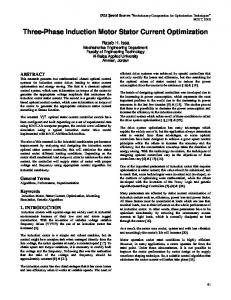
Fundamental (50Hz) = 2.949 , THD= 4.42%
Fundamental (50Hz) = 2.942 , THD= 1.63%
20 15 10 5 0
0
200
400
600
800
Frequency (Hz)
1000
Mag (% of Fundamental)
M ag (% of F undam ental)
From Figure 10, it is apparent that the undulation in the stator current of IM is high during open loop V/f control when compared with the stator current of IM during closed loop V/f control operation and corresponding THD in stator current for both the schemes were presented in Figure 11.
20 15 10 5 0
0
200
(a)
400
600
Frequency (Hz)
800
1000
(b)
Figure 11. THD in stator current of IM (a) during open loop V/f control (b) during closed loop V/f control
5.
EXPERIMENTAL WORK AND RESULTS The Hardware model of the proposed open loop and closed loop V/f controlled IM drive incorporated with PI controlled EPOSLLC is shown in Figure 12 and Table 3 show the experimental parameters used in the proposed configuration. The separate algorithm for open loop and closed loop V/f control topology is developed which is embedded in FPGA spartan-6 processor for generating gate pulse to VSI.
Figure 12. Hardware model composed of 1phase AC supply, Power Electronic converters, FPGA processor, IM and Tektronix Oscilloscope Tablel 3. Experimental Parameters Parameter
Rating
Input AC Supply Inductor Capacitors Diodes Voltage Source Inverter Switches Three phase Induction motor Processor
1 phase, 100V, 50Hz L11 = 3mH, L21 = 2.56mH C21 = 200µF, Co = 1320µF MVR3060, 600V, 30A IGBT Inverter SKM100GB12T4, 1200V, 100A, 20Khz switching Frequency 0.5 hp ,3-phase, 50Hz,400V FPGA Spartan-6
IJPEDS Vol. 5, No. 3, February 2015 : 393 – 403
IJPEDS
ISSN: 2088-8694
401
The IM terminal voltage (line voltage of VSI) and DC link voltage is presented in Figure 13.
(a)
(b)
Figure 13. (a) Line output voltage of VSI (CH2) with x-axis scale (1div. = 5ms) and y-axis scale (1div. = 100V) (b) DC link Voltage (CH2) with x-axis scale (1div. = 25ms) and y-axis scale (1div. = 50V) The speed of IM in the experimental setup is measured at the terminals of Spartan-6 processor through a digital to analog convertor and hence the speed response is measured in terms of voltage. Figure 14 shows the speed response (Channel-1) of IM for 1000rpm reference speed (Channel-2) and the load torque of 0.5N.m applied at 400ms. The result of speed response validates the feasibility of closed loop V/f control over open loop V/f control for the proposed model.
(a)
(b)
Figure 14. Speed response of IM for load disturbance (a) during open loop V/f control (b) during closed loop V/f control with x-axis scale (1div. = 500ms) and y-axis scale (1div. = 166.66rpm) The THD in the stator current during the experimental work is measured and is shown in Figure 15.
(a)
(b)
Figure 15. THD in Stator current of IM (a) during open loop V/f control (b) during closed loop V/f control FPGA Based V/f Control of Three Phase Induction Motor Drives Integrating Super-Lift… (P.Elangovan)
402
ISSN: 2088-8694
The THD in the stator current of IM during open loop V/f control is around 5% and during closed loop V/f control is around 2% which legalizes the simulation result presented in Figure 11.
6.
CONCLUSION This paper presents the improved PI control of EPOSLLC incorporated in the façade end of open loop and closed loop V/f controlled IM drive. Experimental and Simulation results such as DC link voltage, speed response of IM and THD in the stator current of IM are obtained. On observing the speed response of IM, the regulation time for load disturbance is very low for closed loop V/f control of IM drive in both simulation and hardware test, which validates the effectiveness of closed loop V/f control over open loop V/f control without complex design. On the other hand, the speed response of IM during open loop V/f control suggest that such control technique is accepted only for the applications like water pumping, compressors, etc., where the speed change of IM is not required. The DC link ripple free voltage waveform verifies the usefulness of proposed EPOSLLC in both the arrangements of IM drives. The scheme suggested utilize minimum rectified DC voltage for driving a three phase IM and therefore, the design using renewable energy as a source by eliminating the single phase AC supply cascading diode rectifier is possible. Basis of future work has been left for the alteration and implementations of experimental drives under involvement of some other control techniques.
REFERENCES [1] Bimal K Bose. Modern Power Electronics and AC Drives. Prentice Hall, New Delhi, India, 2001, Chap.8. [2] M Harsha Vardhan Reddy, V Jegathesan. Open loop V/f Control of Induction Motor based on hybrid PWM With reduced torque ripple. IEEE International Conference on Emerging Trends in Electrical and Computer Technology (ICETECT), 2011: 331-336. [3] Mineo Tsuji, et al. A Novel V/f Control of Induction Motors for Wide and Precise Speed Operation. IEEE International Symposium on Power Electronics, Electrical Drives, Automation and Motion, 2008: 1130 – 1135. [4] Y Sangsefidi, et al. A Simple and Low-Cost Method for Three-phase Induction Motor Control in High-Speed Applications. IEEE 3rd Power Electronics and Drive Systems Technology (PEDSTC), 2012: 212-217. [5] RamKrishan Maheshwari, et al. An Active Damping Technique for Small DC-Link Capacitor Based Drive System. IEEE Transactions on Industrial Informatics. 2013; 9(2): 848-858. [6] A.M. Hava, et al., “Carrier-based PWM-VSI over modulation strategies: Analysis, Comparison and Design,” IEEE Transactions on Power Electronics, vol.13, no.4, pp.834-841, July 1998. [7] Hatti Natchpong, et al., “Back-to-Back Connected Five-Level Diode-Clamped PWM Converters for Motor Drives,” IEEE Transactions on Industry Applications, Vol.44, No.4, pp. 1268 – 1276, 2008. [8] Kamran Jalili, et al., “Behavior of PWM active front ends in the presence of parallel thyristor converters,” IEEE Transactions on Industrial Electronics, vol. 55, no. 3, pp.1035-1046, Mar. 2008. [9] F.Fleming, et al., “Influence of DC-Link Fluctuations on Three-Phase Induction Motor Drives,” in Proceeding of IEEE Vehicle and Propulsion Conference, pp.748-753, Sept. 2009. [10] V. Grigore, J. Hatonen, J. Kyyra, and T. Suntio, “Dynamics of a buck converter with constant power load,” in Proceeding of IEEE 29th Power Electronics Specialists Conference, pp. 72–78, May 1998. [11] Y. Chen and X. Jin, “Modeling and control of three-phase voltage source PWM rectifier,” in Proceeding of IEEE Power Electronics Motion Control Conference, vol.3, pp. 1–4, Aug. 2006. [12] Nelson Mendez-Gomez, et al., “Development of a Low Cost Induction Motor Drive System using a PVM, Boost Converter and Three-Phase Inverter”, in Proceeding of IEEE 38th Photovoltaic Specialists Conference(PVSC), pp. 001348-001351, June 2012. [13] F.L.Luo and Hong Ye, “Advanced DC/DC Converters,” CRC Press, London, 2003, Chap.3. [14] F.L.Luo and Hong Ye, “Positive output super-lift converters,” IEEE Transaction on Power Electronics, Vol.18, No.1, pp.105-113, Jan. 2003. [15] K. Ramash Kumar and S. Jeevananthan, “PI Control for Positive Output Elementary Super Lift Luo Converter,” International Journal of Electrical and Electronics Engineering, Vol.4, No.7, pp. 440 - 445, 2010. [16] P. Mattavelli, et al., “Small signal analysis of DC-DC converter with sliding mode control,” IEEE Transaction on power electronics, Vol. 12, Issue. 1, pp. 96-102, Jan. 1997. [17] Y. Panov, et al., “Analysis and control design of N paralleled DC-DC converters with master-slave current sharing control,” in Proceeding of Applied Power Electronics Conference, pp.436-442, 1997. [18] P. Comines and N. Munro, “PID controllers: recent tuning methods and design to specification”, in Proceeding of IEEE Control Theory and Applications, vol.149, no.1, pp. 46-53, Jan. 2002.
IJPEDS Vol. 5, No. 3, February 2015 : 393 – 403
IJPEDS
ISSN: 2088-8694
403
BIOGRAPHIES OF AUTHORS P.Elangovan did his BE in Electrical and Electronics Engineering at Kamban Engineering College under Anna University, Tamil Nadu, India. He has completed ME in Power Electronics and Drives at Arunai Engineering College under Anna University, Tamil Nadu, India. Presently, he is pursuing Doctoral degree at Anna University, Tamil Nadu, India and also working as Assistant Professor in the department of EEE at S.K.P. Engineering College, Tamil Nadu, India. He has research publications in refereed International Journals and Conference. His research area includes Power Electronics, Induction Motor Drives and Advanced DC- DC converters.
Nalin Kant Mohanty has secured M.Tech degree in Computer Applications In Industrial Drives from Visveswaraiah Technological University, Karnataka. He received Ph.D from Anna University, Tamil Nadu, India. He is a fellow and registered Chatard Engineer of the Institution of Engineers India. He is Life Member of ISTE, ISCA and SESI. Presently he is working as Professor in the department of Electrical and Electronics Engineering of Sri Venkateswara College of Engineering, Tamilnadu, India. He has more than 15 years teaching experience and published 20 research papers in refereed international journals and Conferences. His research area includes Power Electronics, Electric motor drives and contol, power quality and renewable energy systems.
FPGA Based V/f Control of Three Phase Induction Motor Drives Integrating Super-Lift… (P.Elangovan)