Boardman et al.3 has been one of the most widely used endmember extraction ... to the endmember extraction problem for a scene is provided in real time.
FPGA Design and Implementation of a Fast Pixel Purity Index Algorithm for Endmember Extraction in Hyperspectral Imagery David Valenciaa, Antonio Plazaa, Miguel A. Vega-Rodríguezb, and Rosa M. Péreza a
Neural Networks and Signal Processing Group (GRNPS) Computer Architecture and Logic Design Group (ARCO) Computer Science Department, University of Extremadura Avda. de la Universidad s/n, E-10071 Cáceres, Spain E-mail: {davaleco, aplaza, mavega, rosapere}@unex.es b
ABSTRACT Hyperspectral imagery is a class of image data which is used in many scientific areas, most notably, medical imaging and remote sensing. It is characterized by a wealth of spatial and spectral information. Over the last years, many algorithms have been developed with the purpose of finding “spectral endmembers,” which are assumed to be pure signatures in remotely sensed hyperspectral data sets. Such pure signatures can then be used to estimate the abundance or concentration of materials in mixed pixels, thus allowing sub-pixel analysis which is crucial in many remote sensing applications due to current sensor optics and configuration. One of the most popular endmember extraction algorithms has been the pixel purity index (PPI), available from Kodak’s Research Systems ENVI software package. This algorithm is very time consuming, a fact that has generally prevented its exploitation in valid response times in a wide range of applications, including environmental monitoring, military applications or hazard and threat assessment/tracking (including wildland fire detection, oil spill mapping and chemical and biological standoff detection). Field programmable gate arrays (FPGAs) are hardware components with millions of gates. Their reprogrammability and high computational power makes them particularly attractive in remote sensing applications which require a response in near real-time. In this paper, we present an FPGA design for implementation of PPI algorithm which takes advantage of a recently developed fast PPI (FPPI) algorithm that relies on software-based optimization. The proposed FPGA design represents our first step toward the development of a new reconfigurable system for fast, onboard analysis of remotely sensed hyperspectral imagery. Keywords: Field programmable gate arrays (FPGAs), Pixel purity index (PPI), Hyperspectral, Endmember extraction.
1. INTRODUCTION The term “spectral endmember” is well-known in the remote sensing community, and can be defined as an idealized, pure spectral signature for a class1. This concept is mainly used in hyperspectral imaging, and should be distinguished from the concept of “pure pixel” traditionally adopted in other types of studies, such as those based on multispectral sensors which typically collect information in only a few spectral bands. As opposed to that concept, the term “pixel” in hyperspectral imaging refers to an L-dimensional vector given by hundreds of spectral values corresponding to different wavelengths2. It should be noted that an endmember is generally not a pixel. It is a spectral signature that is completely specified by the spectrum of a single material substance. Accordingly, a pixel vector in hyperspectral imaging is generally called “pure” if its spectral signature is an endmember. The Pixel Purity Index (PPI) algorithm developed by Boardman et al.3 has been one of the most widely used endmember extraction algorithms for hyperspectral data exploitation. One of the main reasons for the success of PPI in the remote sensing community is its publicity and availability in the Kodak’s Research Systems ENVI software package4. Due to this propriety, its detailed implementation has never been available in the literature, and thus, several implementations based on limited published results have been proposed. The overall nature of the algorithm is supervised. First, a pixel purity score is calculated for each point in the image cube by generating k random unit L-dimensional vectors called “skewers.” All the points in the original Ldimensional space comprised by the input data are then projected onto the skewers, and the ones falling at the extremes
Chemical and Biological Standoff Detection III, edited by James O. Jensen, Jean-Marc Thériault, Proc. of SPIE Vol. 5995, 599508, (2005) · 0277-786X/05/$15 · doi: 10.1117/12.631270
Proc. of SPIE Vol. 5995 599508-1
of each skewer are tallied. After many repeated projections to different random skewers, those pixels selected a number of times above a certain cut-off threshold, t, are declared “pure” and loaded into an interactive “L-dimensional visualization tool” (available as a built-in companion piece in ENVI software) and manually rotated until a desired number of endmembers, p, are visually identified as extreme pixels in the L-dimensional data cloud. The PPI algorithm suffers from several drawbacks, as indicated in a previous study5. A relevant shortcoming is the algorithm’s sensitivity to parameters k (number of skewers) and t (cut-off threshold value). Since the skewers are randomly generated, it is generally required that a very large number of iterations be generated to arrive to a satisfactory endmember set in terms of signature purity. Another major issue is the algorithm’s computational complexity. For instance, the PPI algorithm available in ENVI 4.0 version took more than 50 minutes to project every data sample vector of the well-known “Cuprite” hyperspectral scene that will be used later on in experiments (the image consists of 614 samples, 512 lines, 224 spectral bands and a total size of 137 MB) onto 104 skewers in a PC with AMD Athlon 2.6 GHz processor and 512 MB of RAM. This very high number of skewers was required to arrive to a reasonable endmember set. Another shortcoming of the PPI is the requirement of human intervention to manually select a final set of endmembers by visual inspection. Most importantly, the PPI is not an iterative process and does not guarantee its convergence in finite runs in spite of that it may converge asymptotically as claimed by the authors3. Recently, Chang and Plaza6 have proposed a fast software-based implementation of the PPI, called fast PPI (FPPI). It has several advantages over the PPI. First, it makes use of a newly developed concept, virtual dimensionality (VD)2 to estimate the number of endmembers, p, required to be generated. This allows for the replacement of the two parameters, k and t used in the PPI so that the issue of their sensitivity to number of runs and cut-off threshold value is resolved. Second, the FPPI takes advantage of the automatic target generation process (ATGP)2 implemented in the automatic target detection and classification algorithm (ATDCA)2 to generate an appropriate set of initial endmembers that can reduce a significant number of iterations required for the PPI. Third, it provides a new iterative rule and a stopping rule for the algorithm. Most importantly, unlike the PPI which requires a visualization tool to manually select a final set of endmembers, the FPPI is completely automatic and unsupervised. It is terminated as long as the implemented stopping rule is met. Even though the FPPI is able to produce a response in about three minutes for the same hyperspectral scene described above in the same computing environment (even though a Matlab-based implementation was used), certain applications require that the response to the endmember extraction problem for a scene is provided in real time. Such is the case of military applications, or those dealing with environmental monitoring or hazard/threat assessment and tracking, including wildland fire detection, oil spill mapping and chemical and biological standoff detection1. In this paper, we develop a hardware-based version of the FPPI algorithm to increase its computational performance by resorting to FPGA reconfigurable boards. The proposed FPGA design represents our first step toward the development of a system for onboard analysis of hyperspectral imagery. It should be noted that most currently available parallel processing systems in remote sensing are directed towards the exploration of massive data archives which have been already transmitted to Earth, while a highly desirable goal is to have the data processed in real time and before its transmission to Earth. This may allow scientists to overcome an existing limitation in many remote sensing and observatory systems, i.e., the bottleneck introduced by the bandwidth of the downlink connection from the observatory platform. The proposed methodology was designed in Handel-C7 language for high-level prototyping, using Celoxica’s DK 3.1 tool8. Then, it was implemented on a Virtex-II FPGA from Xilinx, Inc.9 The remainder of the paper is organized as follows. Section 2 describes the FPPI algorithm and our proposed parallelization strategy. Section 3 describes a systolic-array based implementation for the FPPI. Section IV briefly discusses the Handel-C code. Section V presents an experimental assessment of both software- and hardware-optimized versions of FPPI with regards to the original PPI algorithm available in ENVI software. Section VI concludes with some remarks and future research lines.
2. FPPI ALGORITHM AND PARALLELIZATION STRATEGIES Before describing our parallel algorithm, we first provide a step-by-step description of the original FPPI algorithm. Although the algorithm makes use of the VD concept2 and the ATGP algorithm5 to improve the original PPI, both techniques have not been implemented in parallel in this work. As a result, we assume that the number of endmembers, p, to be extracted by the algorithm is known in advance, and that a set of p intelligently generated skewers is already available. Future work should be directed towards the parallelization of both techniques. With the above assumptions in mind, a step-by-step description of the FPPI algorithm in6 is provided below.
Proc. of SPIE Vol. 5995 599508-2
FPPI Algorithm 1. Initialization: Assume that p, the number of endmembers required to generate is estimated by the VD concept, and let
{skewer }
( 0) p j j =1
2.
be an initial set of p skewers generated by ATGP algorithm.
Iterative rule: At iteration k ≥ 0 , for each skewer j(k ) project all the data sample vectors onto this particular skewer j(k ) to find
those sample vectors that are at its extreme positions to form an extrema set, denoted by S extrema ( skewer j(k ) ) . Despite the fact that a different skewer j generates a different extrema set S extrema ( skewer j(k ) ) , it is very likely that some sample vectors may appear in more than one extrema set. Define an indicator function of a set S, I S (r ) by the following expression: ⎧1; if r ∈ S I S (r ) = ⎨ and N PPI (r ) = ⎩0; if r ∉ S
3.
Pure pixel candidate selection:
{ }
Find the sample vectors, denoted by r j( k ) 4.
p j =1
I
(k ) j S extrema ( skewer j )
(r ) .
(1)
, that produce the first p largest values of N PPI (r ) .
Stopping rule:
Find the p largest values of N PPI
∑
in the joint set of
{N
PPI
}
(r j( k ) )
p
{
}
Υ N PPI ( skewer j( k ) ) j =1
p j =1
and let
{N ( skewer )} be those vectors corresponding to the obtained p largest values of N , denoted by {e } . If {N ( skewer )} = {N ( skewer )} , that is, {e } = {e } , then there is no more ( k +1) j
PPI
( k +1) p j j =1
PPI
p
PPI
j =1
( k +1) j
p
j =1
PPI
(k ) j
p
j =1
( k +1) p j j =1
(k ) p j j =1
endmember has been replaced. In this case, the algorithm is terminated. Otherwise, let k ← k + 1 and go to step 2. while (not end) for every skewer in the VD do max_value = MINIMUM_VALUE pos = INITIAL_POINT (x,y) for every line do for every column in a line do result = dot-product(sample,skewer); if result > max_value then Tally extreme pixel and its spatial coordinates (x,y) endif endfor endfor for each pixel in the list do increment PPI count of the pixel at spatial coordinates (x,y) endfor endfor change set of skewers according to results evaluate stopping rule if (stopping rule = true) then end = true endif endwhile Table 1. Pseudo-code description of steps 2-4 in the FPPI algorithm.
Proc. of SPIE Vol. 5995 599508-3
In order to implement steps 2-4 of the FPPI algorithm in parallel, we first investigated which parts of the algorithm are likely to represent the most significant fraction of the execution time. Obviously, projecting a large number of data sample vectors onto a set of skewers via dot products is a highly parallelizable operation since there are no data dependences involved. Therefore, our first approximation to parallel designed was aimed at speeding up computational performance of the highly time-consuming process accomplished in step 2. Table 1 provides a pseudo-code of the calculations carried out by this step. After analyzing the code in Table 1, we can adopt two main strategies for parallelization. A first option would be to partition the dataset (and the main loop), thus maintaining the spectral identity of each pixel to avoid having individual pixels split among processing elements. This option is particularly appealing in remote sensing applications, where the minimum calculation unit is generally the spectral signature contained in a pixel vector as a whole. On other hand, partitioning the data in terms of spectral information may also introduce a significant communication overhead and additional data dependences, as demonstrated in our recent study10. As a result, we generally prefer to keep the spectral identity of both skewers and pixels instead of breaking them into several processing elements. This is expected to introduce less requirements in terms of FPGA resources. With the above ideas in mind, Table 2 shows a pseudo-code description of the parallel code used in this work. while (not end) for every partition of the image do for each sample in partition do in parallel for each skewer in the set do in parallel Resultij=dot-productij(samplei,skewerj) endfor endfor Calculate local extrema and tally spatial coordinates (x,y) endfor calculate global extrema and tally spatial coordinates (x,y) change set of skewers according to results if (old skewer set = new skewer set) then end = true endif endwhile Table 2. Pseudo-code description of a parallel implementation of steps 2-4 in the FPPI algorithm.
In the following section, we describe our design strategy to implement the parallel code shown in Table 2, aimed at enhancing replicability and reusability of slices in the FPGA (e.g., resources in a Virtex FPGA are divided into slices) through the use of systolic array design.
3. SYSTOLIC ARRAY-BASED DESIGN One of the main advantages of systolic array-based implementations11 is that they are able to provide a systematic design procedure that allows for the derivation of a element processing structure and an interconnection pattern (even in a very first approximation), which can then be easily ported to real hardware configuration via Handel-C7 and EDIF8 descriptions. Through this procedure, we can also calculate the data dependences in a very straightforward manner, along with subsequent shift operations that need to be implemented in the hardware structure, thus improving over available design procedures which are mainly based on trial-and-error practices. The adopted procedure also allows for a more practical and easy-to-handle strategy to implement algorithms in hardware, which does not really require detailed knowledge on hardware description languages. The systematic design used in this work is based on the general idea that
(
)
an algorithm can be described by a tuple A = I N , C , D, X , Y , where I N is a set of indexes, C represents the volume of calculations, D denotes the data dependences, and X , Y are the inputs and outputs to the algorithm, respectively.
(
)
An algorithm denoted by A would be equivalent to another algorithm A' = I' N , C' , D' , X' , Y' if and only if the
⎡π⎤ ⎣S ⎦
following properties are satisfied: i) X' = X and Y' = Y ; ii) C' = C ; and iii) A biyective function T = ⎢ ⎥ exists, such
( )
that D' = T (D ) and I' N = T I N . It should be noted that π is defined in the first M indexes of A' , and provides
Proc. of SPIE Vol. 5995 599508-4
information about the corresponding operation that takes place in each node, i.e., π : I N → I' M . Similarly, S is defined in the remaining indexes of A' , and provides information on the processing cells which are going to execute the operation, i.e., S : I N → I' N - M . It should be noted that π must preserve data dependences, i.e., π ⋅ d i > 0 with
D = (d 1 , d 2 ,⋅ ⋅ ⋅, d N ) , and S must preserve the biyective property in T . Taking into account the above framework for systolic algorithm design, we only need to introduce minor modifications to the main loop in Table 2 in order to make it suitable for parallel implementation under the proposed systematic methodology. Specifically, the algorithm should be expanded to a 3-dimensional space11, as shown by Table 3. for i = 1 to Number of Pixels in partition do for k=1 to Number of skewers in partition do Result(i,k,0)=0 for j=0 to number of bands do Sample(i,0,j)=Pixel(i,j) Skewer(0,k,j)=Skewer(k,j) Result(i,k,j)=Result(i,k,j-1)+ Skewer(i,k,j)*Sample(i,k,j) endfor endfor endfor Table 3. Modification of the main loop in the parallel FPPI algorithm to adapt it to a systolic array-based implementation.
From the code outlined above, we can obtain a set of data dependences and the values for π = [t 11 , t 12 , t 13 ] . Firstly, if
Dresult = (i, k , j ) − (i, k , j − 1) = (0,0,1) , and taking into account that π ⋅ d i > 0 , then t 13 > 0 . The same reasoning can Dsample = (i, k , j ) − (i − 1, k , j ) = (1,0,0 ) , thus obtaining t 11 > 0 , and to be applied to
Dskewer = (i, k , j ) − (i, k − 1, j ) = (0,1,0) , resulting in t 12 > 0 . Therefore, we can conclude that π = [1,1,1] . In order to maintain the biyective condition of T , we set the values of S using combinations of 1’s and 0’s. At this point, we also need to decide which calculations will be stored in each processing element, and what would be the total volume of information that will be communicated to neighboring processing elements which are directly interconnected throughout the network. We must also take into account which kind of hardware architecture will be our target, along with its advantages and limitations, in particular, in terms of resources available and communication speed between the host and the FPGA board. Therefore, our design should be aimed at maximizing computational power of the hardware and minimizing the cost of communications. This is particularly relevant in our specific application, where more than 200 data values will be handled for each intermediate result, a fact that may introduce problems related with limited resource availability and inefficiencies in hardware replication and reusability. Having the above issues in mind, we have opted
⎡0 1 0 ⎤ ⎥ , which results in the following data shifts: ⎣1 0 0⎦ ⎡0 ⎤ ⎡0 1 0 ⎤ ⎢ ⎥ ⎡0 ⎤ =⎢ ⎥ × ⎢0⎥ = ⎢ ⎥ , i.e., local results remain static at each processing element, ⎣1 0 0⎦ ⎢1⎥ ⎣0⎦ ⎣ ⎦
for a solution given by S = ⎢
S × Dresult
S × D pixels
⎡1⎤ ⎡0 1 0 ⎤ ⎢ ⎥ ⎡ 0 ⎤ =⎢ ⎥ × ⎢0⎥ = ⎢ ⎥ , i.e., pixels will be shifted from top to bottom, ⎣1 0 0⎦ ⎢0⎥ ⎣1⎦ ⎣ ⎦
S × Dskewers
⎡0 ⎤ ⎡ 0 1 0 ⎤ ⎢ ⎥ ⎡1 ⎤ =⎢ ⎥ × ⎢1⎥ = ⎢ ⎥ , i.e., skewers will be shifted from left to right, ⎣1 0 0⎦ ⎢0⎥ ⎣0⎦ ⎣ ⎦
Proc. of SPIE Vol. 5995 599508-5
(2)
(3)
(4)
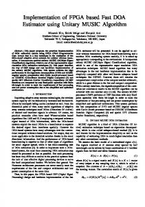
Before addressing the implementation of the proposed systolic-based implementation in Handel-C, Fig. 1 provides a block diagram of the proposed architecture for the implementation of FPPI, where “s” stands for “skewer” and “p” stands for “pixel.” Finally, “VD” denotes the virtual dimensionality concept, which defines the number of elements in the processing matrix as a function of the number of endmembers, p. As will be shown in section V, our experimental results reveal that the best performance is achieved when the size of partitions is set to p. We have also experimentally tested that an increase in the partition size may lead to under-utilization of processing elements and significantly lower speedups. P21
P'1
P.E.
P.E.
H H
P.E.
P.E.
Figure 1. Pseudo-code diagram of the proposed systolic array design for implementation of the FPPI algorithm.
4. HANDEL-C IMPLEMENTATION The final decision on implementing our design using Handel-C instead of other well-known hardware description languages such as VHDL or Verilog was taken on the account that it is possible to generate hardware versions of hyperspectral analysis algorithms using a high-level-based approach and in relatively short time. Several projects have been developed to bring new methods for describing hardware implementations, most notably, Ocapi-xl13 or SpecC14. However, our experience shows that, for this kind of reconfigurable hardware, it may be better to follow the guidelines imposed by the vendors. With the above remarks in mind, the DK3.1 software package emerges as one of the most interesting alternatives, in particular, taking into account its portability to UNIX-type operating systems. In this regard, the main advantage of Handel-C design language is its simplicity, where the design can be defined and evaluated using a pseudo-C programming style. For illustrative purposes, the source code in Handel-C of the proposed FPPI implementation is shown in Table 4. This code is based on 8 skewers and 8 sample pixel vectors for each partition. For a full understanding of the piece of code shown in Table 4, we point to reference material7. The implementation provided in Table 4 was compiled and transformed to an EDIF specification automatically by using the DK3.1 software package. With this specification, and using other tools such as Xilinx ISE9 to simplify the final steps of the hardware implementation, we also incorporated hardware-specific limitations and constraints to the mapping process into a VirtexII FPGA. These tools allowed us to evaluate the total amount of resources needed by the whole implementation, along with sub-totals related to different functional units available in the FPGA that will be discussed in the following section, along with our results in terms of algorithm performance and execution time.
5. EXPERIMENTAL RESULTS In this section, we provide an experimental assessment of the proposed FPGA-based implementation, not only in terms of parallel performance and hardware implementation efficiency, but also in terms of endmember extraction accuracy in the context of a real application based on a well-known hyperspectral data set. Resultingly, our proposed Virtex-II hardware implementation will be compared to the original FPPI algorithm implemented in Matlab, and to the PPI available from Research Systems ENVI software using well-known hyperspectral data.
Proc. of SPIE Vol. 5995 599508-6
void main(void){ unsigned int 16 max[VD]; unsigned int 16 end[VD]; unsigned int 3 i; //The size is defined by the VD unsigned int 3 k; //The size is defined by the VD unsigned int 7 j; //Number of bands par(i=0;i