Jul 29, 2015 - Email: {takei, hasitha, hariyama, kameyama}@ecei.tohoku.ac.jp. AbstractâIn this ... tiling to designing an FPGA-based FDTD accelerator by using an ..... http://www.nallatech.com/opencl-fpga-accelerator-cards.html. Int'l Conf.
72
Int'l Conf. Par. and Dist. Proc. Tech. and Appl. | PDPTA'15 |
FPGA-Oriented Design of an FDTD Accelerator Based on Overlapped Tiling Yasuhiro Takei, Hasitha Muthumala Waidyasooriya, Masanori Hariyama and Michitaka Kameyama Graduate School of Information Sciences, Tohoku University Aoba 6-6-05, Aramaki, Aoba, Sendai, Miyagi, 980-8579, Japan Email: {takei, hasitha, hariyama, kameyama}@ecei.tohoku.ac.jp
Abstract— In this paper, we introduce the overlapped tiling to designing an FPGA-based FDTD accelerator by using an OpenCL compiler. The OpenCL compiler for FPGA enables us to reduce the design time of the FPGA-based accelerators. However, the FPGAbased accelerator generated from common OpenCL codes cannot accelerate the processing efficiently in some applications such as an FDTD computation. To accelerate the FDTD computation, global memory access can be reduced by storing the small partition of the electronic and magnetic fields with enclosed areas into the local memory. According to the result of the implementation of the FDTD accelerator on the FPGA, the processing speed with overlapped tiling is far faster than that without overlapped tiling. Moreover, the processing speed is faster than a GPU when the number of grids is small. Keywords: FPGA, OpenCL, FDTD method, Hardware accelerator, Ovrerlapped tiling
1. Introduction Recently, very large scale computing systems are required for processing three-dimensional image processing, electromagnetic simulation, fluid dynamics and DNA sequence and so on. However, the power consumption of high performance computer systems increases year by year. Low power and high performance systems for big data processing are strongly required. FPGA-based accelerators are attracting attention for such high-performance computing systems. The power consumption of FPGAs is about one tenth of that of GPUs. Moreover, very large scale architectures for high performance computing can be implemented on a FPGA because of the advancement of the process technology. One of the major problems of the FPGA-based
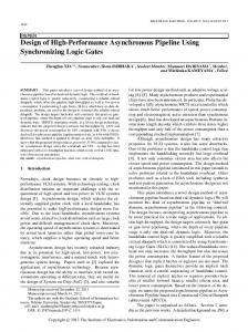
accelerator is a difficulty of designing the architecture. The software-based design on CPUs and GPUs requires only a software code by using C language or CUDA [1]. On the other hand, the hardware-based design on FPGAs requires the design of circuit modules for calculations, controls and connecting to the host PC by using a hardware design language(HDL). To get the good performance on the FPGA-based accelerator, the knowledge of the circuit design and a very long time for designing the hardware are required. To solve this problem, Altera Corporation released Altera SDK for OpenCL [2] which is the OpenCL compiler for FPGAs. OpenCL is the programming language for multicore architectures, which is standardized by the Khronos group [3]. The source code of the OpenCL is constituted by a host code and kernels. The initialization, the data-transfer from the host PC to the accelerator and running the kernels are described in the host code. The parallelized computation on the accelerator is described in the kernel code. As a feature of the OpenCL, a common source code can be run on different architectures, such as multicore CPUs, GPUs, Intel Phi processors, CELL processors and so on, by using suitable compilers for each architecture. In order to implement an OpenCL code on the FPGA board, Altera SDK for OpenCL can be used as shown in Fig.1. This compiler generates FPGA-based hardwares for calculation and connecting to the host PC by PCI express automatically from the OpenCL code. Hence, we can implement the FPGAbased accelerators without the HDL design. Figure 2 shows the architecture model generated by Altera SDK for OpenCL. This architecture has kernel pipelines, a memory controller, a PCI express controller and interconnections. Compared with conventional accelerators such as GPUs, this architecture has a high degree of
Int'l Conf. Par. and Dist. Proc. Tech. and Appl. | PDPTA'15 |
������ �� ��
�������������������������������������� ��� �
73
���� ��� ���
��� ����
������� ����
���� ��� ����
����������� �� � �� �� ��
��� ����
�������
��������
����
���
�� �� ������ �
��� �� ���
�� �� ������ �
�� �� ������ �
���
���������� �� � �� �� ��
Fig. 2: The architecture model generated by Altera SDK for OpenCL
����
��� � ���
� �����
Fig. 1: OpenCL implementation on the FPGA
freedom for changing and optimizing the architecture of the kernel pipelines and interconnections. Altera SDK for OpenCL is used in recent studies such as fractal image processing [4], AES encryption encoding [5] and information filtering [6]. These studies achieved low power and high performance computing compared with CPUs and GPUs. In our previous work [7], we implemented the FDTD method accelerator by using Altera SDK for OpenCL. However the processing speed of the FPGA-based accelerator was slower than that of the GPU. In this paper, we improve the OpenCL code for the FDTD method in order to achieve the better performance on the FPGA. We introduce the overlapped tiling in the electromagnetic field to reduce the global memory access.
2. Implementation of the FDTD method by using OpenCL The FDTD method [8] has been widely used in electromagnetic simulation, analysis of sound wave and so on. Since the computation of the FDTD method has a high degree of parallelism, there are many works which use computer clusters, GPUs [9], [10] and FPGAs [11],[12] to accelerate the FDTD method. Equation (1) shows the electric field computation and Eqs.(2) and (3) show the magnetic field computation. Electric and magnetic fields in x, y, z directions are denoted by
E and H respectively. The time step is denoted by n and the coordinates of the 2D fields are denoted by i and j . Note that the boundaries of the electric and magnetic fields are calculated differently. Parameters P x, P y, Qx, Qy are determined by the permittivity, the permeability, the size of grids, and the length of the time step. A detailed description of the FDTD method is given in [8]. Ezn+1 (i, j) = Ezn (i, j) o n n+ 1 n+ 1 −Py (i, j) Hx 2 (i, j + 1/2) − Hx 2 (i, j − 1/2) n n+ 1 o n+ 1 +Px (i, j) Hy 2 (i + 1/2, j) − Hy 2 (i − 1/2, j) (1) n+ 21
Hx
n− 21
(i, j + 1/2) = Hx
(i, j + 1/2)
−Qy (i, j) {Ezn (i, j + 1) − Ezn (i, j)} n+ 21
Hy
n− 21
(i + 1/2, j) = Hy
(i + 1/2, j)
−Qx (i, j) {Ezn (i
+ 1, j) − Ezn (i, j)}
(2)
(3)
In our previous OpenCL code in [7], the electric and magnetic field data in the global memory are accessed in parallel. Hence the performance of the execution of this kernel strongly depends on the bandwidth of the global memory. However, the bandwidth of the global memory on the FPGA is narrower than that of the GPU as shown in Table 1. Hence the FPGA accelerator cannot achieve better performance than the GPU. To achieve high performance computing on the FPGA board, it is important to improve the OpenCL code by reducing the global memory access.
74
Int'l Conf. Par. and Dist. Proc. Tech. and Appl. | PDPTA'15 |
Table 1: Bandwidth of the global memory FPGA (StratixV 5SGXA7) 25.6GB/s
GPU(Geforce GTX 580) 192.4GB/s
To reduce the global memory access, we introduce the overlapped tiling as described in section 3.
3. Overlapped tiling Ovelapped tiling is one of the advanced techniques of the loop tiling. Loop tiling divides a big loop into smaller loops to optimize the cache hit rating [13]. This technique is widely used in the stencil computation includes the FDTD computation [14],[15]. In the stencil computation, the value of neighbor grids are used for the computing the value at the next time step as shown in Fig 3. In order to reduce the global memory access by using the loop tilling, the grid data in enclosed area of a tile must be also stored into the local memory. Hence the overlapped tiling is proposed in order to reduce the communication overhead [16]. Figure 4 shows an example of the overlapped tiling model of the FDTD computation. Let n × m be the area of the tile and t be the iteration of time steps with the local memory access, (n+2t)×(m+2t) grids in the electric and magnetic fields are stored into the local memory. This enclosed area of the tile is often called "ghost zone" [17], and the ghost zone is overlapped neighbor tiles. The area of a ghost zone expands as the iteration of the time steps with the local memory access. The FDTD computations in this area are done without the global memory access. After the FDTD computations finish, the values in the tile area is stored into the global memory. The overlapped tiling is often used in the stencil computation on GPUs since the overhead of the synchronization between processing elements can be reduced [17], [18]. Figure 5 shows the flowchart of the FDTD computation with overtapped tiling. The electric and magnetic field data in the tile with the ghost zone is transferred from the global memory to the local memory. Then the FDTD computations in the tile are done prescribe time steps. These FDTD computations are fully pipelined with the pragma of loop unrolling [2], [19]. After the FDTD computations finish, the electric and magnetic field data in the tile are transferred from the local memory to the global memory.
Fig. 3: Stencil computing with neighbor grids ������ � �� � ��� � � ���
����
��� ��� ��� �
���� �� Fig. 4: Overlapped tiling
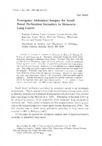
4. Evaluation We implement the FDTD accelerator by using OpenCL on "Nallatech P395-D8 FPGA board" [20]. This FPGA board has the Altera StratixV GX C8,four DDR3-SDRAMs(8GB×4) and a PCI-Express. We use Altera SDK for OpenCL 13.1 for the compilation on the FPGA. Figure 6(a) shows the simulation model. This model has N × N grids (N=128,256,512). The area of tiles as shown in Fig. 4 is 32 × 8 grids. The electric field at (N/2,N/2) is excited as shown in Fig.6(b). The boundary area is considered as the perfect conductor (Ez = 0). The single-precision floating-point is used for the calculation. To optimize the architecture of the FDTD accelerator, it is important to consider with the tradeoff between the amount of the computation and the times of the global memory access. This tradeoff depends on the iterations of time steps with local memory access. Hence we evaluate a relationship between the performance on the FPGA and the iterations of time steps with local memory access. Table 2 shows the resource usage of the FDTD accelerators with one karnel pipeline as shown in Fig.
Int'l Conf. Par. and Dist. Proc. Tech. and Appl. | PDPTA'15 |
Start: n=0 Initial data transfer ���� ��� �� � � ��� ���� ���������� ��
����� �� �� ���������� ��
��� ��� �� �� No
Table 3: Processing time of the FPGA with overlapped tiling(s) (Time steps=1000) Grids 128×128 256×256 512×512
FPGA without tiling 2.030 2.780 5.400
FPGA with tiling 0.070 0.250 1.050
Table 4: Processing time of the CPU, the GPU and the FPGA(s) (Time steps=1000) Grids 128×128 256×256 512×512
CPU (Corei7 920) 0.249 1.294 11.232
GPU (GTX 580) 0.156 0.203 0.249
FPGA (P395-D8) 0.070 0.250 1.050
loop>TSTEP
Yes
���� ��� �� � ���� � ��� No
75
T>Max Yes Finish
Fig. 5: The flowchart of the FDTD method with overlapped tiling
2. As the time step iterations with local memory access increase, the resource usage becomes larger since the number of the pipeline stages on the kernel pipeline increases by using the loop unrolling. Figures 7(a) and 7(b) show the relationship of the processing time and iterations of the time steps with local memory access (TSTEP_LOOP) on the FPGA and the GPU (nvidia Geforce GTX 580). As shown in these figures, the processing time on the FPGA is the smallest when TSTEP_LOOP is five. Moreover, most of the processing time of the GPU is larger than that of the FPGA. One of the reasons is that the tile size is not suitable for the warp size on the GPU. These results show that the OpenCL code which is suitable for FPGAs is not always suitable for GPUs. Table3 shows the comparison of the processing time on the FPGA. The processing speed of the FPGA with overlapped tiling is about 5-20 times as fast as that of the FPGA without overlapped tiling. This result shows that it is effective for accelerate of the FDTD computation to reduce the global memory access by
using the overlapped tiling. To compare the processing speed of the FPGAbased accelerator with that of CPUs and GPUs, we implement the FDTD method by C language on "Intel Corei7 920", and by OpenCL without tiling on "nvidia Geforce GTX 580". Table 4 shows the comparison of the processing time on the FPGA and the CPU and GPU. When the number of grids is small, the processing speed of the FPGA is the fastest in all devices. On the other hand, the processing speed of the FPGA is slower than that of the GPU when the number of grids is large. In order to get better performance on the FPGA, the degree of parallelism should be increased by implementing more kernel pipelines.
5. Conclusion In this article, we implement the FDTD computing with overlapped tiling on the FPGA board by using the OpenCL compiler. The processing speed of the FPGA with overlapped tiling is about 5-20 times as fast as that of the FPGA without overlapped tiling. Moreover, the processing speed of the FPGA is faster than that of GPU when the number of grids is small. To optimize the performance on the FPGA-based architecture, it is important to estimate the performance from the design parameters such as the iterations of time steps with local memory access and the area of the tiles. In future works, we formulate the estimation of the processing time from input design parameters and the optimal design parameters are chosen for implementing the best architecture on the FPGA.
76
Int'l Conf. Par. and Dist. Proc. Tech. and Appl. | PDPTA'15 |
Time steps 3 5 6
Table 2: Resource usage LEs FFs DSPs 105906(20%) 156517(15%) 12(1%) 144072(26%) 187679(18%) 20(1%) 148848(28%) 201450(19%) 24(1%)
� � ��� �
�
���������
���������� ������ ���� (a) Simulation model
�� �
����
�� (b) Excitation of the electric field
Fig. 6: Set up of the simulation
Acknowledgment This sutdy is supportted by MEXT KAKENHI grant number 24300013 and Grant-in-Aid for JSPS Fellows grant number 15J04973. Also, this study is supported by OTB Transnational Inc.
References [1] NVIDIA Corporation, “NVIDIA CUDA Programming Guide” Ver2.2.1, 2009. [2] Altera corpolation, “Altera SDK for OpenCL Programming Guide”, http://www.altera.co.jp/literature/hb/openclsdk/aocl_programming_guide.pdf [3] Khronos group, http://www.khronos.org/opencl/
RAMs 1225(48%) 1403(55%) 1563(61%)
[4] D. Chen and D. Singh, “Fractal Video Compression in OpenCL:An Evaluation of CPUs, GPUs, and FPGAs as Acceleration Platforms”, Design Automation Conference (ASPDAC) 18th Asia and South Pacific, pp.297-304, 2013. [5] Nallatec, “40Gbit AES Encryption Using OpenCL and FPGAs”, http://www.nallatech.com/images/stories/technical _library/white-papers/40_gbit_aes_encryption_using_opencl _and_fpgas_final.pdf [6] D. Chen and D. Singh, “Using OpenCL to Evaluate the Efficiency of CPUs, GPUs, and FPGAs for Information Filtering ”, Field Programmable Logic and Applications (FPL), 2012 22nd International Conference on. IEEE, pp.5-12, 2012. [7] Yasuhiro Takei, Hasitha Muthumala Waidyasooriya, Masanori Hariyama and Michitaka Kameyama, “Design of an FPGABased FDTD Accelerator Using OpenCL ", International Conference on Parallel and Distributed Processing Techniques and Applications (PDPTA), pp.371-375, 2014 [8] H. S. Yee, “Numerical Solution of Initial Boundary Value Problems Involving Maxwell’s Equations in Isotropic Media”, IEEE Transactions on Antennas and Propagation, Vol.14, No.3, pp.302-307, 1966. [9] Z. Bo, X. Zheng-hui, R. Wu, L. Wei-ming and S. Xinqing, “Accelerating FDTD algorithm using GPU computing”, International Conference on Microwave Technology & Computational Electromagnetics (ICMTCE), pp.410-413, 2011. [10] T. Nagaoka and S. Watanabe, “A GPU-based calculation using the three-dimensional FDTD method for electromagnetic field analysis”, International Conference on Engineering in Medicine and Biology Society (EMBC), pp.327-330, 2010. [11] W. Chen, P. Kosmas, M. Lesser and C. Rappaport, “An FPGA Implementation of the Two Dimensional Finite Difference Time Domain (FDTD) Algorithm”, ACM/SIGDA International Symposium on Field-Programmable Gate Arrays(FPGA), pp.213-222, 2004. [12] K. Sano, Y. Hatsuda, W. Luzhou and S. Yamamoto, “Performance Evaluation of Finite-Difference Time-Domain (FDTD) Computation Accelerated by FPGA-based Custom Computing Machine”, Interdisciplinary Information Sciences, Vol.15, No.1, pp.67-78, 2009. [13] M.E. Wolf and M.S. Lam, 1991 “A Data Locality Optimizing Algorithm", ACM Sigplan Notices, pp.30-44, 1991. [14] G. Rivera and C. Tseng “Tiling Optimizations for 3D Scientific Computations", ACM/IEEE SC2000 Conference, 2000. [15] Z. Li , Y. Song, “Automatic Tiling of Iterative Stencil Loops", ACM Transactions on Programming Languages and Systems , pp.975-1028, 2004. [16] S. Krishnamoorthy, M. Baskaran, U. Bondhugula, J. Ramanujam, A. Rountev, P. Sadayappan, “Effective automatic Parallelization of Stencil Computations", ACM SIGPLAN conference on Programming language design and implementation, pp.235-244, 2007. [17] J.Meng, and K. Skadron, “A Performance Study for Iterative
Int'l Conf. Par. and Dist. Proc. Tech. and Appl. | PDPTA'15 |
��������� �� �
��
���� ���� ���� ���� ����
��
���
��
��� ��� ��� �
�
� ����������
�
�
(a) (N=256) ��������� �� �
��
���� ���� ���� ����
���
����
��
��� ��� �
�
� ����������
�
�
(b) (N=512)
Fig. 7: Processing time vs time step iterations on local memory
Stencil Loops on GPUs with Ghost Zone Optimizations", International Journal of Parallel Programming 39.1,pp115142,2011. [18] J. Holewinski, L.-N. Pouchet, and P. Sadayappan, “HighPerformance Code Generation for Stencil Computations on GPU Architectures", In Proceedings of the 26th ACM international conference on Supercomputing (ICS ’12), pp.311-320, 2012 [19] Altera corpolation, “Altera SDK for OpenCL Optimization Guide”, http://www.altera.co.jp/literature/hb/openclsdk/aocl_optimization_guide.pdf [20] Nallatec, “OpenCL FPGA Accelerator Cards”, http://www.nallatech.com/opencl-fpga-accelerator-cards.html
77