FRAME BASED TEXTURE CLASSIFICATION BY CONSIDERING VARIOUS SPATIAL NEIGHBORHOODS Karl Skretting and John H˚ akon Husøy University of Stavanger, Department of Electrical and Computer Engineering N-4036 Stavanger, Norway, E-mail:
[email protected] ABSTRACT In this paper we briefly describe the Frame Texture Classification Method (FTCM) and the tiled-floor texture model on which it is based. For a test image pixel a feature vector is formed based on a small spatial neighborhood, and FTCM calculate its distance to the frames, i.e. the dictionaries, one frame for each texture class under consideration. The frame where the distance is smallest gives the texture class the pixel is assumed to belong to. The texture model gives some guidance to how the feature vectors should be formed, many different ways to do this are described, all being in accordance with the texture model. In the experiments we investigate many different sizes and shapes for the neighborhood used when forming the feature vectors. The experiments are done on some commonly used test images of natural textures. FTCM is flexible when selecting a neighborhood and many patterns give excellent classification results. 1. INTRODUCTION Classification and segmentation of texture content in digital images is an important part of many image analysis methods. Tuceryan and Jain [1] give a comprehensive overview of texture classification. Possible applications can be grouped into: 1) texture analysis, i.e. find some appropriate properties for a texture, 2) texture classification, i.e. identify the texture class in a homogeneous region, 3) texture segmentation, i.e. find a boundary map between different texture regions of an image. The boundary map may be used for object recognition and scene interpretation in areas such as medical diagnostics, geophysical interpretation, industrial automation and image indexing. Finally, 4) texture synthesis, i.e. generate artificial textures to be used for example in computer graphics or image compression. Some examples of applications are presented in [2, 3, 4, 5, 6]. For human beings it is quite easy to recognize different textures in images. We look at the whole image at once and find the texture features at the same time as we do image segmentation. Both these tasks are
highly knowledge dependent, we know a lot of common textures and know in which shapes and contexts they usually occur. Computer based algorithms do not (yet) have this large amount of knowledge available and typically do texture classification and image segmentation in two clearly separated parts. Also, texture classification algorithms typically have two main parts: A local feature vector is found, which is subsequently used for texture classification or segmentation. The feature vector is generated, a lot of different methods can be used, from the pixels in a spatial neighborhood of a center pixel. The methods for feature extraction may be loosely grouped as statistical, geometrical, model-based, and signal processing (filtering) methods [1]. For the filtering methods the feature vectors are often built as variance estimates, local energy measures, for each of the sub-bands of a filter bank. Also, there are numerous classification or pattern recognition methods available: The Bayes classifier is probably the most common one [7, 8]. The minor max-selector is a simple one that can be used if each entry in the feature vector measures the similarity to, or corresponds to, a texture class. Nearest neighbor classifier, vector quantization (codebook vectors represent each class) [9] and learning vector quantization (LVQ) (codebook vectors define the decision borders) [10, 11, 12], neural networks, watershed-based algorithm [13], and support vector machines (SVM) [14] are other methods. In this paper Frame Texture Classification Method (FTCM) should be regarded as a supervised vector classification method. As will be explained in Section 2 FTCM is particulary well suited under the assumption that the vectors within each class are a sparse linear combination of elements from a frame, i.e a dictionary, of finite (moderate) size. This assumption will be true for feature vectors generated from a texture synthesized by the tiled-floor texture model. FTCM is thus related to other texture classification methods which depend on classification of the feature vectors. It is possible that the results presented in this paper may be useful also when other vector classification methods are used for texture classification.
We will particulary mention the relationship between FTCM and the SVM scheme as used in [15]. SVM finds a set of support vectors for each texture and this set identifies a hyperplane which separates the given texture from the rest of the textures, while FTCM finds a set of frame vectors for each texture and this set is trained to efficiently represent the given texture by a sparse linear combination and thus identifying the texture. 2. FRAME TEXTURE CLASSIFICATION METHOD The FTCM is a supervised texture classification method. It was first introduced in [16], and is also presented in [17] and [18]. Here follows a brief presentation of the underlaying deterministic texture model, followed by the two parts of FTCM. 2.1. The tiled-floor texture model The main result of this subsection is that it is reasonable to model a small texture image block as a sparse linear combination of frame elements. In the proposed texture model a texture is modelled as a tiled floor, where all tiles are identical. We let the coordinate system be aligned to match a tile, such that the center of the first tile is given by (x, y) = ( 12 , 12 ), and the corners are (0, 0), (1, 0), (0, 1), and (1, 1). The color, or gray-level, at a given position on the floor is given by a continuous periodic two-dimensional function which we denote c(x, y) = c(x − bxc, y − byc). A finite number, denoted M , of control points, denoted ci , are placed on each tile. The function is defined as a bilinear interpolation of four of the (closest) control points, i.e. c(x, y) = a1 ci1 + a2 ci2 + a3 ci3 + a4 ci4 . The bilinear interpolation is actually a convex combination, with a1 +a2 +a3 +a4 = 1 and 0 ≤ ak ≤ 1. Samples of c(x, y) on a rectangular sampling grid, not necessarily aligned with the coordinate system implied by the first tile, constitute the digital texture image. By choosing 1) the number and positions of control points in a tile, 2) the gray-level value (color) of each of the control points, 3) the orientation of the sampling grid relative to the coordinate system aligned with the tiles, denoted by angle α, and finally, 4) the distance between neighboring sampling points, denoted by δ, in the sampling grid, we obtain a digital texture image. We will now look closer on a small block of pixels from the texture image. This block is arranged into a size N vector, x = [x(1), x(2), . . . , x(N )]T , x(1) is the upper left pixel and the rest are numbered columnwise. Remember that each entry of x, i.e. each pixel, is a convex combination of four control points
taken from a finite set of M control points. Given the model above, it was shown in [18] that the vector x is a convex combination of four frame vectors taken from a finite set of at most M N 2 frame vectors. 2.2. Frame design For a particular texture image, specified by the model above, i.e. by control points and by a sampling grid, we could find the correct frame. But in FTCM a more general method is used to design the frame, the frame is not designed based on knowledge on how the texture image was made, but only based on a set of training vectors generated from an example image. Each training vector is approximated by a linear combination of (three or) four frame vectors. The frame is designed to achieve the best total sparse representation for all the training vectors. How the training vectors are formed is discussed in Section 3. The parameters used during design are N , K, L and s. The length of the training (and frame) vectors is N . The number of vectors in the frame is denoted K. For practical reasons it should be quite small, we may use N ≤ K ≤ 10N ¿ M N 2 . To avoid overtraining the number of training vectors L should be much larger than K, K ¿ L. The sparseness to use in the approximation is denoted s, here we use the values s = 3 and s = 4. For each texture class the training vectors are arranged into a N × L matrix, X = [x1 x2 . . . xL ]. We want to find a frame with K frame vectors, F = [f1 f2 . . . fK ], such that each of the training vectors can be approximated by a sparse combination of the frame vectors, xl ≈ Fwl where wl has at most s non-zero entries. Having W = [w1 w2 . . . wL ] the objective function to be minimized, with a sparseness constraint on W, is J = J(F, W) = kX − FWk2 . (1) Finding the optimal solution to this problem is difficult if not impossible. We split the problem into two parts to make it more tractable, similar to what is done in the GLA design algorithm for VQ codebooks [19]. The iterative solution strategy presented below results in good, but in general suboptimal, solutions to the problem. The algorithm starts with a user supplied initial frame F0 , usually K arbitrary vectors from the set of training vectors, and then improves it by iteratively repeating two main steps: 1. Wt is found by vector selection using frame Ft . The objective function is J(W) = kX−Ft Wk2 , and a sparseness constraint is imposed on W. 2. Ft+1 is found from X and Wt , where the objective function is J(F) = kX − FWt k2 . This
gives:
¡ ¢−1 Ft+1 = XWtT Wt WtT
(2)
Then we increment t and go to step 1. t is the iteration number. The first step is suboptimal due to the use of practical vector selection algorithms, while the second step finds the F that minimizes the objective function. 2.3. Classification Texture classification of a test image, containing regions of different textures, is the task of classifying each pixel of the test image to belong to a certain texture. This is done by generating test vectors from the test image using the same method as when the training vectors were generated. A test vector is represented in a sparse way using each of the different frames that were trained for the textures under consideration, the set of C frames {F(i) }. The distance between test vector xl and frame F(i) is the 2-norm (length) of the representation error for the best sparse representation of the test vector, (i) (i) (i) (i) dl = krl k and rl = xl −F(i) wl . Each test vector xl corresponds to a pixel of the test image. Classification consists of selecting the index i for which the norm, or norm squared, of the representation error, (i) (i)T (i) krl k2 = rl rl , is minimized. Direct classification based on the norm squared of the representation error for each test vector (pixel) gives quite large classification errors, but the results can be substantially improved by smoothing the error images. Smoothing is reasonable since it is likely that neighboring pixels belong to the same texture. For smoothing we have used the separable Gaussian low-pass filter. The effect of smoothing is mainly that more smoothing gives better classification within the texture regions but lower resolution, i.e. often more classification errors along the borders between different texture regions. To improve texture segmentation a nonlinearity may be included before the smoothing filter is applied, [20]. We have found that the logarithmic nonlinearity often gives the best results, [16]. 3. SELECTING PIXELS IN LOCAL NEIGHBORHOOD We will here show that the training and test vectors (feature vectors) can be made in many different ways and still be in accordance with the model in subsection 2.1. Let us assume that the block around each pixel is of size 13 × 13, giving N = 169 as the length of vector x. The “perfect” frame is F of size N × K where K = M N 2 , M is the number of control points on one tile. In accordance with the model we have
x = Fw, where w is a sparse vector with only four non-zero entries. Let another feature vector x0 be formed as x0 = Ax where A is a N 0 × N matrix, N 0 ≤ N . Keeping w the same as above, i.e. still sparse, this gives x0 = A(Fw) = (AF)w = F0 w, and we see that also x0 can be represented by a linear combination of four frame vectors taken from a finite set of frame vectors, F0 = AF. Suppose each row in A has only one non-zero entry. This gives the case where the feature vectors are formed by a pattern of pixels around the center pixel. Some examples are illustrated in patterns 1-9 in Figure 1. The non-zeros entries of A are here assumed to be 1, but it is also possible to form a weighted pattern. Without restrictions on the entries of A each element of x0 is a linear combination of the elements in x. This is the same as the output of different FIR-filters applied on the pixels in the local neighborhood of the central pixel, each row of A gives the coefficients of each filter. The patterns 14-18 in Figure 2 are formed this way. In the model a vector is formed by a bilinear interpolation of frame vectors, i.e. a sparse convex combination where each coefficient 0 ≤ ak ≤ 1 and P ak = 1. In vector selection, and the equation x = Fw, a sparse linear combination is used. The coefficients, ak , are the non-zero entries of w. It is not trivial to include the convex constraint into the vector P selection algorithm, but an affine constraint, i.e. ak = 1, can be implemented without any changes to the linear vector selection algorithm. Let · 0
x =
b x
¸
· 0
and F =
b f1
b f2
··· ···
b fK
¸ . (3)
where b 6= 0. Then the linear combination x0 = F0 w must also be an affine combination. Patterns 10-13, 15, 16 and 18 in Figure 2 all have an extra fixed element added. Pattern 10 is like pattern 1 except for the fixed element, 11 is like 5, 12 is like 3, 13 is like 6, 15 is like 14, and 18 is like 17. Here we have argued that the feature vectors may be generated in many different ways from the pixels in a spatial neighborhood of the central pixel. Neither the model nor the theory give any clear guidance to which is better. Obviously each vector should contain the necessary texture information for this particular center pixel, but it does not need to contain information on the neighboring pixels (smoothing). For the complexity of the methods, the smaller feature vectors should be preferred. In the next section extensive experiments are presented, all the 18 different methods shown in Figure 1 and Figure 2 are tested.
Pattern 1, N=9
Pattern 2, N=16
Pattern 3, N=25
(a)
(b)
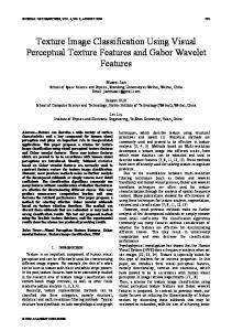
Figure 3: Two of the nine test images used. Pattern 4, N=49
Pattern 5, N=13
Pattern 6, N=21
4. EXPERIMENTS
Pattern 7, N=21
Pattern 8, N=49
Pattern 9, N=39
Figure 1: Pixels around the center pixel, marked by a square, used to form the local feature vector for the 9 simple cases. N is the number entries in the feature vector, here it the same as the number of pixels in each pattern.
Pattern 10, N=10
Pattern 11, N=14
Pattern 12, N=26
Pattern 13, N=22
Pattern 14, N=25
Pattern 15, N=26
Pattern 16, N=25
Pattern 17, N=17
Pattern 18, N=18
Figure 2: More patterns, here an extra fixed value element is added to each feature vector, except for pattern 14 and 17. Feature vectors for patterns 14 to 18 are formed by filtering over the pixels indicated by plus sign, for pattern 17 and 18 the Daubechies 7-9 wavelet filters are used. N is the number entries in the feature vector.
FTCM and the 18 different patterns for the feature vectors, described in Section 3, were tested both for synthesized texture images made based on the model and for natural real textures. It turned out that all patterns achieved very well on the synthesized test images, and the differences between them were marginal. Thus, this section presents the results for the natural textures. As in [18] we choose to use the nine test images of Randen and Husøy [11] for natural real textures. These consist of 77 different natural textures, taken from three different and commonly used texture sources: The Brodatz album, the MIT Vision Texture database, and the MeasTex Image Texture Database. The test images are denoted (a) to (i). (a) and (b) are shown in Figure 3, all are shown in Figure 11 in [11], where also a more detailed description of the test images can be found1 . The same test images were also used in other papers [21, 8, 13, 15, 22]. The excellent performance of FTCM compared to the other methods was reported in [18], the purpose here is to compare the different patterns to each other. The experiments started by designing the frames to be used, one frame for each kind of training vector and texture under consideration. The frame parameters, see Subsection 2.2, used were: N as given by the pattern, K = 6N but minimum 100 and maximum 200, s = 3 for N < 30 and s = 4 for N ≥ 30, and L = 14400. 250 iterations were done. During classification of each test image we use only the frames corresponding to the textures that are present in the test image. A logarithmic nonlinearity and a separable Gaussian low-pass filter were used. The standard deviation σ in the filter varied, but here we present the complete results only for σ = 10, the size of this low pass filter was cut at approximately 2σ at each end, giving the filter size 39 × 39 pixels. These results are shown in Table 1. 1 The training images and the test images are available at http://www.ux.his.no/˜tranden/
Pattern (parameters: N × K, s) 1 (9 × 100, 3) 2 (16 × 100, 3) 3 (25 × 150, 3) 4 (49 × 200, 4) 5 (13 × 100, 3) 6 (21 × 126, 3) 7 (21 × 126, 3) 8 (49 × 200, 4) 9 (39 × 200, 4) 10 (10 × 100, 3) 11 (14 × 100, 3) 12 (26 × 156, 3) 13 (22 × 132, 3) 14 (25 × 150, 3) 15 (26 × 156, 3) 16 (25 × 150, 3) 17 (17 × 102, 3) 18 (18 × 108, 3) 11+15+18, see text
a 4.0 4.9 5.2 4.8 4.7 4.4 4.6 4.2 4.5 3.4 5.9 5.9 5.3 3.8 8.6 8.2 4.7 7.1 7.4
b 9.3 10.2 14.1 15.8 12.0 9.9 13.3 18.3 15.4 10.7 6.7 12.7 9.3 10.6 6.7 9.2 8.5 8.6 5.8
c 12.0 8.5 8.7 9.3 8.2 10.4 9.0 10.8 10.4 6.2 8.0 9.4 10.9 5.6 6.7 12.5 7.7 7.3 7.0
d 26.6 10.5 7.0 10.7 10.2 13.2 9.6 8.4 9.2 24.7 5.8 6.3 8.2 18.1 11.0 12.0 14.4 9.7 5.8
e 19.4 8.1 6.7 6.4 9.9 7.1 8.9 8.5 7.7 8.7 5.4 6.3 7.4 5.2 5.6 5.5 6.5 6.3 4.7
f 28.2 20.7 18.0 16.9 26.9 23.5 23.3 16.3 18.5 22.5 23.5 19.0 17.8 17.2 16.3 19.7 18.9 16.5 16.5
g 26.3 18.1 14.4 15.8 16.7 17.9 16.6 17.3 16.2 23.9 14.3 15.7 20.4 11.2 13.5 16.6 15.1 18.3 13.1
h 32.4 25.3 23.0 15.0 24.9 19.3 16.1 16.0 15.7 33.1 21.2 16.5 15.1 17.9 16.1 17.4 18.4 17.6 16.4
i 28.8 22.8 23.0 24.0 17.3 27.2 26.6 23.8 24.6 21.4 10.0 15.7 19.4 19.0 17.2 21.4 14.2 15.0 9.9
Mean 20.8 14.3 13.4 13.2 14.5 14.8 14.2 13.7 13.6 17.2 11.2 11.9 12.6 12.1 11.3 13.6 12.0 11.8 9.6
Table 1: Classification errors, given as percentage wrongly classified pixels, for different methods and natural test images. Let us look closer at the average results for the 9 test images. These are presented in Figure 4, on the left side for σ = 1, here low-pass filtering is done using a small 3 × 3 and narrow filter, and on the right side for σ = 10. We note that with little low-pass filtering the longer feature vectors perform best, while using more appropriate low-pass filtering it seems that longer feature vectors do not improve the results. The most probable explanation is that the longer feature vectors also contain some of the “smoothing” information. We also conclude that almost all methods seems to capture the essential texture information quite well. Methods 11, 15, and 18 do all very well. To see how an extra constant element added to the feature vector influence on the results we compare the results, taken from Table 1, of the six patterns, 1, 5, 3, 6, 14 and 17 to the six similar patterns, 10, 11, 12, 13, 15 and 18. We note that adding an extra element give better results almost always, the means (of the means) are 14.6 and 12.7 percent wrongly classified pixels. The conclusion seems to be clear, adding the extra element improves the results. This is in line with the model where an affine combination is preferred to a linear combination. Looking at the details the conclusion is not that clear, three of the test images, c, e and g, are best classified using method 14. Generally, the details give more scattered results, indicating that the choice of pattern is dependent on the test image. Also, training has a random element both in selection of the training vectors, the initial
frame, and the training process, resulting in slightly different frames each time a frame is trained. This random effect obviously has an impact on the results, and can explain some of the scattering. More work is needed to understand this better. To get even better results it is possible to do averaging without smoothing. This is possible since several representation errors for each pixel, one for each of the patterns, are available. Averaging these for patterns 11, 15, and 18 before smoothing (and before the logarithmic nonlinearity is applied) gives the results presented in last line of Table 1. 5. CONCLUSION Many of the different sizes and shapes for the neighborhood used to form the feature vectors gave excellent results when FTCM was used for vector classification. It seems that the small 3 × 3 pattern, used in method 1 and 10, is too small. Adding just a few more pixels, as in pattern 2, 5 and 11, seems to capture the texture information well and gives very good results. Pattern 11 seems best, considering both simplicity and results. To get optimal classification results several patterns can be combined. 6. REFERENCES [1] M. Tuceryan and A. K. Jain, “Texture analysis,” in Handbook of Pattern Recognition and Computer Vision, C. H. Chen, L. F. Pau, and P. S. P. Wang, Eds. Singapore: World Scientific Publishing Co, 1998, ch. 2.1, pp. 207–248.
Mean for the 9 test images, σ = 1
Mean for the 9 test images, σ = 10
65
21
1
1
20 10
19
Percentage wrongly classified pixels.
Percentage wrongly classified pixels.
60
5
55
11
6 13
2
7
50 17
18
3 16 12 14 15
45
10
17
16
15
6 5
2
16 3
5
10
15
20
25
30
35
40
45
Length of feature vectors, N.
8
9
4
13
8
50
11
14 12
17
12
40
7
14
13
4 9
18
18
15
11
5
10
15
20
25
30
35
40
45
50
Length of feature vectors, N.
Figure 4: The average percentage wrongly classified pixels for the 9 test image, here with σ = 1 in low-pass filter to the left and σ = 10 to the right. [2] R. J. Dekker, “Texture analysis and classification of ERS SAR images for map updating of urban areas in the Netherlands,” IEEE Trans. Geosci. Remote Sensing, vol. 41, no. 9, pp. 1950–1958, Sept. 2003.
no, and A. Santos, “A multichannel [13] N. Malpica, J. E. Ortu˜ watershed-based algorithm for supervised texture segmentation,” Pattern Recognition Letters, vol. 24, no. 9-10, pp. 1545–1554, June 2003.
[3] M. K. Kundu and M. Acharyya, “M-band wavelets: Application to texture segmentation for real life image analysis,” International Journal of Wavelets, Multiresolution and Information Processing, vol. 1, no. 1, pp. 115–149, 2003.
[14] S. Li, J. T. Kwok, H. Zhu, and Y. Wang, “Texture classification using the support vector machines,” Pattern Recognition, vol. 36, no. 12, pp. 2883–2893, Dec. 2003.
[4] F. Mendoza and J. M. Aguilera, “Application of image analysis for classification of ripening bananas,” Journal of Food Science, vol. 69, no. 9, pp. 471–477, Nov. 2004. [5] S. Arivazhagan and L. Ganesan, “Automatic target detection using wavelet transform,” EURASIP Journal on Applied Signal Processing, vol. 2004, no. 17, pp. 2663–2674, 2004. [6] S. Singh and M. Singh, “A dynamic classifier selection and combination approach to image region labelling,” Signal Processing Image Communication, vol. 30, no. 3, pp. 219– 231, Mar. 2005. [7] M. Unser, “Texture classification and segmentation using wavelet frames,” IEEE Trans. Image Processing, vol. 4, no. 11, pp. 1549–1560, Nov. 1995. [8] S. Liapis, E. Sifakis, and G. Tziritas, “Colour and texture segmentation using wavelet frame analysis, deterministic relaxation, and fast marching algorithms,” Journal of Visual Communication and Image Representation, vol. 15, no. 1, pp. 1–26, Mar. 2004. [9] G. F. McLean, “Vector quantization for texture classification,” IEEE Trans. Syst., Man, Cybern., vol. 23, no. 3, pp. 637–649, May/June 1993. [10] T. Kohonen, “The self-organizing map,” Proc. IEEE, vol. 78, no. 9, pp. 1464–1480, Sept. 1990. [11] T. Randen and J. H. Husøy, “Filtering for texture classification: A comparative study,” IEEE Trans. Pattern Anal. Machine Intell., vol. 21, no. 4, pp. 291–310, April 1999. [12] C. Diamantini and A. Spalvieri, “Quantizing for minimum average misclassification risk,” IEEE Trans. Neural Networks, vol. 9, no. 1, pp. 174–182, Jan. 1998.
[15] K. I. Kim, K. Jung, S. H. Park, and H. J. Kim, “Support vector machines for texture classification,” IEEE Trans. Pattern Anal. Machine Intell., vol. 24, no. 11, pp. 1542– 1550, Nov. 2002. [16] K. Skretting, “Sparse signal representation using overlapping frames,” Ph.D. dissertation, NTNU Trondheim and Høgskolen i Stavanger, Oct. 2002, available at http://www.ux.his.no/˜karlsk/. [17] K. Skretting and J. H. Husøy, “Texture classification using sparse frame based representations,” in NORSIG-02, Tromsø/Trondheim, Norway, Oct. 2002, also available at http://www.ux.his.no/˜karlsk/. [18] ——, “Texture classification using sparse frame based representations,” EURASIP Journal on Applied Signal Processing, 2005, accepted for publiction, to be printed autumn 2005. [19] A. Gersho and R. M. Gray, Vector Quantization and Signal Compression. Norwell, Mass., USA: Kluwer Academic Publishers, 1992. [20] M. Unser and M. Eden, “Nonlinear operators for improving texture segmentation based on features extracted by spatial filtering,” IEEE Trans. Syst., Man, Cybern., vol. 20, pp. 804–815, 1990. [21] M. Acharyya, R. K. De, and M. K. Kundu, “Extraction of features using M-band wavelet packet frame and their neuro-fuzzy evaluation for multitexture segmentation,” IEEE Trans. Pattern Anal. Machine Intell., vol. 44, no. 12, pp. 1639–1644, Dec. 2003. ainen, [22] T. Ojala, K. Valkealahti, E. Oja, and M. Pietik¨ “Texture discrimination with multidimensional distributions of signed gray-level differences,” Pattern Recognition, vol. 34, no. 3, pp. 727–739, Mar. 2001.