From Design to Test with UML – Applied to a Roaming Algorithm for Bluetooth Devices Zhen Ru Dai1 , Jens Grabowski2 , Helmut Neukirchen2 , and Holger Pals3 1
Fraunhofer FOKUS, Competence Center TIP, Kaiserin-Augusta-Allee 31, D-10589 Berlin, Germany,
[email protected] 2 Institute of Computer Engineering, University of L¨ ubeck, Ratzeburger Allee 160 D-23538 L¨ ubeck, Germany,
[email protected] 3 Institute for Informatics, Software Engineering for Distributed Systems Group, University of G¨ ottingen, Lotzestrasse 16-18, D-37083 G¨ ottingen, Germany {grabowski,neukirchen}@cs.uni-goettingen.de
Abstract. The UML Testing Profile provides support for UML based model-driven testing. This paper introduces a methodology of how to use the testing profile in order to modify and extend an existing UML design model for test issues. As a case study, a new roaming algorithm for bluetooth devices has been developed at the University of L¨ ubeck, is modelled using UML. The usability of the UML Testing Profile will be explained by applying it to this model.
1
Introduction
The Unified Modeling Language (UML) is a visual language to support the design and development of complex object-oriented systems [1]. While UML models focus primarily on the definition of system structure and behaviour, they provide only limited means for describing test objectives and test procedures. Furthermore, the growing system complexity increases the need for solid testing. Thus, in 2001, a consortium is built by the Object Management Group (OMG) in order to develop a UML 2.04 profile for the testing domain [3, 4]. Currently, the UML Testing Profile project [5] is at its finalization stage. A UML profile provides a generic extension mechanism for building UML models in particular domains. The UML Testing Profile is such an extension developed for the testing domain. It bridges the gap between designers and testers by providing a means for using UML for both system modeling and 4
UML 2.0 has been adopted by the OMG in June 2003. Currently, it is at its standardization finalization stage. In this paper, we follow the approach of U2 Partners consortium [2], who is the main submitter of UML 2.0. When talking about UML, we only refer to version 2.0.
2
Zhen Ru Dai, Jens Grabowski, Helmut Neukirchen, Holger Pals
test specification. This allows a reuse of UML design documents for testing and enables test development in an early system development phase [6]. In this paper, we provide a methodology of how to apply UML Testing Profile concepts to an existing UML design model effectively. As a case study, the methodology will be evaluated by applying it to a UML model for roaming with Bluetooth devices. This paper is structured as follows: After a short introduction of UML Testing Profile in the next section, a methodology will be provided (Section 3) where mandatory and optional test aspects of UML Testing Profile are discussed. In Section 4, we will introduce potential roaming techniques for data transfer scenarios using Bluetooth hardware devices as a case study. A corresponding UML model is given in Section 5. Section 6 evaluates our testing methodology by applying it to the UML model. Some conclusions are drawn in Section 7.
2
The UML Testing Profile (UTP)
The UML Testing Profile provides concepts to develop test specifications and test models for black-box testing [7]. The profile introduces four logical concept groups covering the aspects: test architecture, test behavior, test data and time (Figure 1) [8]. Together, these concepts define a modeling language for visualizing, specifying, analyzing, constructing and documenting a test system.
Test Architecture Concepts
Test Behavior Concepts
Test Data Concepts
Time Concepts
SUT Test components Test suite Test configuration Test control Arbiter Utility part
Test objective Test case Defaults Verdicts Validation action Test trace Log action
Wildcards Logical partition Coding rules
Timer Time zone
Fig. 1. UML Testing Profile Concepts
The test architecture group covers the concepts for specifying test components, the interfaces of and connections among test components and between test components and System Under Test (SUT). The test behavior group embodies concepts of specifying actions necessary to evaluate the objective of a test. Test behaviors can be defined by any behavioral diagram of UML 2.0, e.g. as interaction diagrams or state machines. The test data group includes concepts for specifying test data. The time group defines concepts to constrain and control test behavior with regard to time.
From Design to Test with UML 2.0
3
3
A Methodology for UML Testing Profile
In this section, we introduce a methodology for using the UML Testing Profile effectively after having received a detailed design model which should be tested. In the following, we determine design model to be the system design model in UML and the test model to be the UML model enriched with UML Testing Profile concepts. Having a design model, a tester may have to specify tests for the system. This can be done by extending the design model with UML Testing Profile concepts. The following aspects must be considered when transforming a design model into a test model: First of all, define a new UML package as the test package of the system. Import the classes and interfaces from the system design package in order to get access to message and data types in the test specification. Next, start with the specification of the test architecture and continue with test behavior specifications. Test data and time are mostly already comprised in either the test architecture (e.g. timezone or data pool) or test behavior (e.g. timer or data partitioning) specifications. Below, issues regarding test architecture and test behavior specifications are listed. They are subdivided into two categories: mandatory issues and optional issues. Mandatory issues can normally be retrieved directly from the design model, while optional issues are specific to test requirements and, therefore, can seldom be retrieved from existing UML diagrams. However, they are not always needed for the test model. The most important issues are the specification of SUT components, test components, test cases and verdict settings: I. Test architecture: i. Mandatory: – Assign the system component(s) you would like to test to SUT. – Depending on their functionalities, test components have to be defined. Try to group the system components (except the SUT) to test components. – Specify a test suite class listing the test attributes and test cases, also possible test control and test configuration. ii. Optional: – In order to define the ordering of test case execution, specify the test control. The simplest way is to string the test cases together. In more complex test controls, loops and conditional test execution may be specified. – Test configuration can be easily retrieved by means of existing interaction diagrams: Whenever two components exchange messages with each other, assign a communication channel between the components. If there is no interaction diagram defined in the design model, connect the test components and SUT to an appropriate test configuration so that the configuration is relevant for all test cases included in the test suite.
4
Zhen Ru Dai, Jens Grabowski, Helmut Neukirchen, Holger Pals
– Determine utility parts within the test configuration. – Determine an arbiter for test verdict arbitration. – Assign timezones to the components. Timezones are normally needed if a distributed test system is built and time values of different components need to be compared. – Provide coding rule specifications. II. Test behavior: i. Mandatory: – For designing the test cases, take the given interaction diagrams of the design model and change (i.e. rename or group) the instances and assign them with stereotypes of the UML Testing Profile (i.e. test component or SUT) according to their functionalities. – Assign verdicts at the end of each test case specification. Usually, the verdict in a test case is set to pass. ii. Optional: – Specify default behaviors using wildcards for setting a fail or inconclusive verdict. – Define time events by means of timers or time constraints.
4
A Case Study: Roaming with Bluetooth Devices
Bluetooth is an established standard for short-range wireless communication. The Bluetooth specification enables small devices to interact within a short range. The standards related to Bluetooth include both the hardware (radio, baseband and hardware interface) and basic protocol layers that allow Bluetooth software to run on different Bluetooth enabled devices. The current Bluetooth standard does not support roaming of Bluetooth devices [9]. If a device is losing the link to its master, no provision is made to transfer the connection to another master. Nevertheless, roaming within Bluetooth piconets might be useful in some cases, e.g. for Bluetooth-enabled network access using LAN access points. Assuming having more than one Bluetooth LAN access point, roaming might be useful for having a seamless connection even while moving. 4.1
The Application
The need for a basic roaming support for Bluetooth devices descends from a project at the University of L¨ ubeck and several other academic and industrial partners [10]. The project is situated in medical environment. Its goal is to replace the traditional cable-based monitoring of patients during surgical treatments with a wireless transmission of the patient’s monitoring data using Bluetooth hardware devices. By transmitting the sensor data via radio, the mobility of the patient will be increased significantly, the number of artifacts (often caused by the cables themselves) are reduced as well as the overall cost for the replacement of broken cables.
From Design to Test with UML 2.0
5
Sensor data like electrocardiogram (ECG), temperature or blood pressure are gathered at a mobile device, digitized and transmitted via radio to fixed units (receivers). The mobile device is fixed at the patient’s bed (or the patient itself) which may be moved during the entire monitoring period. One of the advantages of this wireless monitoring is a continuous data transmission throughout all the different stages the patient passes through (e.g. preparation, anesthesiology, surgery, wake up, intensive care). Thus, the connection between the mobile devices and the receivers mounted at the hospital’s walls or ceilings must be handed over from one receiver to the next while the patient is moving. The receivers have to be mounted in such a way that the entire area the mobile device can reach is covered. To allow a seamless connection, the areas covered by the antennas of two adjacent receivers are overlapping. In this scenario, different units (e.g. sensor units, digitizing unit and radio transmission unit) share the same rechargeable battery pack. The electric power consumption plays an important role in the design of the system. As a consequence, a mobile device only consists of a small embedded device including the Bluetooth chipset and a low-current microcontroller without a complete Bluetooth protocol stack running on it. From now on the term Bluetooth device denominates a device using a Bluetooth hardware unit to send and receive data without necessarily using the complete Bluetooth protocol stack. 4.2
Roaming for Bluetooth
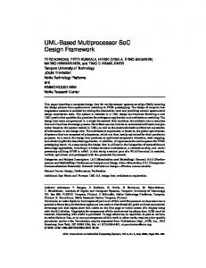
Our roaming approach assumes that all masters are connected to a fixed network. The mobile devices are usually moving along the masters. If a slave runs the risk of losing connection to its actual master, the connection must be handed over to the next master. The slave prevents the loss by periodically checking the quality of the link to the master. This can be done using the HCI Get Link Quality command defined in the Bluetooth standard [9]. If the quality drops below a certain threshold value the next master will be chosen. The slave tries to connect directly to the next master using the Bluetooth paging mechanism, knowing to which master it has to contact to next. Herefore, movements of the slave are tracked by a Location Server, which updates and provides slave’s spacial information in form of a roaming list whenever the slave changes its master. The current master receives the roaming list from Location Server and forwards it to the slave [11]. The Activity Diagram in Figure 2 shows the activities of a slave necessary for roaming. The slave tries to connect to a master. If the connection is successful, the updated roaming list is transferred to the slave and data can be sent. In parallel, the link quality between slave and master is observed. If the quality gets bad, the slave will look in the roaming list for a new master and try to connect to that master directly. If, for any reason, no connection can be established, a warning message is sent to the user (e.g. by a warning light or a special sound indicating that a problem has occurred). Another warning message is sent to the last master. If the connection to the last master is still alive, the reception
6
Zhen Ru Dai, Jens Grabowski, Helmut Neukirchen, Holger Pals Slave BTRoaming Activities
Connect to new master [connection confirmed]
[new master != NULL]
send data
[link quality == good]
get link quality
[connection not confirmed]
get roaming list
[link quality == bad]
calculate new master [new master == NULL]
send warnings
Fig. 2. Roaming Algorithm as Activity Diagram
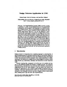
of a warning message can be used to initiate appropriate exception handling mechanisms. Figure 3 shows the design of the protocol stack resulting from the proposed roaming approach: Special roaming layers (Slave Roaming Layer and Master Roaming Layer) are added. They take care of the correct transfer of the connections. Our roaming approach makes no use of the higher protocol stacks of Bluetooth. Therefore, the roaming layers are implemented directly on the hardware interface called Host Controller Interface (HCI). The application layers are set upon the roaming layers. The interface from roaming layer to application layer is called Slave Roaming Interface (SRI) and Master Roaming Interface (MRI), respectively.
Slave: Slave Application
Master: Data Exchange
Master Application MRI
(Virtual Connection)
SRI Slave Roaming Layer
Master Roaming Layer
HCI
HCI Link Manager
Link Manager Baseband
LNI
Slave BT− Hardware
Master BT− Hardware
Bluetooth Radio
Baseband
LAN
Bluetooth Radio Radio Connection
Fig. 3. Protocol Stack with Roaming Layer
Fixed Connection
From Design to Test with UML 2.0
7
Additionally, a master is specified as a fixed network node. Thus, it also embodies the LAN protocol stacks to be able to communicate with the local network. The interface between the Master Roaming Layer and the Ethernet is called Local Network Interface (LNI).
5
From Design ...
In addition to the Bluetooth roaming algorithm presented in the previous section, we also investigated the applicability of UML 2.0 [4, 12, 1] for modeling our roaming approach. The usage of a standardized and widely accepted modeling language like UML has several advantages: It supports the communication among soft- and hardware designers, avoids ambiguities in the description and allows the usage of commercial tools for documentation, analysis, implementation and testing during system development. In this section, we describe an architectural view on our Bluetooth roaming scenario by means of a UML package diagram, show the communication among the UML Bluetooth classes in form of sequence diagrams and present the local behavior of a slave by using a UML state machine. Figure 4 shows a UML package diagram with different classes involved in our Bluetooth roaming approach. Similarity can be recognized between the classes in Figure 4 and the Bluetooth protocol stacks in Figure 3. The slave classes are called Slave Application, Slave BTRoaming and Slave BT-HW (Bluetooth Hardware). The interfaces SRI and HCI connect the class components with each other. A Slave BT-HW is connected to one Master BT-HW. Similar to the slave classes and interfaces, there are the classes Master Application, Master BTRoaming and Master BT-HW and the interfaces MRI and HCI on the master’s side. Master BTRoaming class is connected to the Location Server, which represents a node in the local network, by means of the interface LNI. Location Server owns a Net Struct Table and several Slave Roaming Lists. There is exactly one roaming list for each slave. The Net Struct Table is a static table which provides information BluetoothRoaming Master Application
Slave Application
MRI
SRI 1
Slave BTRoaming
Master BTRoaming
HCI
HCI
*
Net_ Struct_ Table 1
LNI 1
Slave * BT−HW
1
Master BT−HW
1
Location Server
1
1
Fig. 4. Bluetooth Roaming Package
* Slave_ Roaming_ List
8
Zhen Ru Dai, Jens Grabowski, Helmut Neukirchen, Holger Pals sd BT-Roaming : Slave Application
: Location Server
: Slave BTRoaming
Master1_R : Master BTRoaming
Master1_BT : Master BT-HW
: Slave BT-HW
con_request
Master2_BT : Master BT-HW
Master2_R : Master BTRoaming
con_request con_accept con_confirm
con_confirm con_confirm connected(Slave)
connected(Slave) ref
RList := makeList(Slave)
roamingList(RList,Slave)
roamingList(RList,Slave)
roamingList(RList)
roamingList(RList)
data
data get_link_quality {0,5..0,5}
quality(good) data
data get_link_quality quality(bad) ref
newMaster := Search_NewMaster() con_request
con_request con_accept
con_confirm
con_confirm
con_confirm
connected(Slave)
connected(Slave)
ref
RList := makeList(Slave)
roamingList(RList,Slave)
roamingList(RList,Slave) roamingList(RList)
roamingList(RList)
data
data get_link_quality quality(good)
Fig. 5. Roaming Scenario Design
about the structure of the local network and the physical position of the masters as necessary for calculating each Slave Roaming List. In contrast, the instances of Slave Roaming List are changing dynamically. The Slave Roaming List is updated by the Location Server whenever a slave roams to a new master. Since a copy of each updated Slave Roaming List is transferred to its slave there is also a one-to-one association between Slave Roaming List and Slave BTRoaming. In Figure 5, the sequence diagram depicts a detailed roaming scenario. There are eight different instances in the diagram: One location server instance called Location Server, three slave instances named Slave Application, Slave BTRoaming, Slave BT-HW, and four masters instances with BT-HW and BTRoaming instances for each of Master1 and Master2.5 5
The application instances of Master1 and independent from the application layers.
Master2
are not shown because roaming is
From Design to Test with UML 2.0
9
sd Search_NewMaster(): String :Slave Application
:Slave BTRoaming
:Slave BT-HW
Search_ NewMaster
NewMaster := RList.nextElement alt [NewMaster !=NULL] NewMaster
[NewMaster == NULL] "warning: RList empty" "warning: RList empty" NULL
Fig. 6. Search NewMaster() Function
The scenario starts with a connection request from the application instance of the Slave to Master1.6 The hardware instance Master1 BT confirms the connection establishment and the roaming instance Master1 R informs the Location Server that Slave is now under its responsibility.7 Hence, the Location Server calculates and updates the roaming list RList of the Slave and sends it to Master1 R. Master1 R forwards the RList immediately to the Slave Roaming instance. Now, data can be exchanged between Slave and Master1 until the link quality becomes bad. The verification of the link quality is performed periodically every 0.5s between the Slave BTRoaming instance and the Slave BT-HW Instance. If the link quality is proved to be bad, a new master is needed. For that, the function Search NewMaster() is called by Slave BTRoaming. This function looks up in the RList and picks out the name of the next neighbouring master and returns the name of the new Master to Slave BTRoaming (Figure 6). In case that RList is empty, a warning signal will be sent to both the Slave Application and the old Master (if it is still possible). In our scenario (in Figure 5), the new Master is Master2. Thus, a connection request will be sent from Slave Roaming instance to Master2 R instance. If Master2 BT-HW confirms a successful connection establishment, the Location Server will again be informed about the new status of Slave. It updates the roaming list and sends it to the roaming instance of the new master. Master2 R forwards the list to Slave BTRoaming and data exchange can be started. A set of scenarios, like the ones presented in Figures 5 and 6, can be analyzed and used to generate local views of class behaviors. One possibility of UML to describe such local behaviors are state machines. 6
7
In order to provide an intuitive understanding of the signals, we abstracted from the signal names in the Bluetooth specification [9]. Since there is a lot forwarding traffic between the instances, we only describe the source and the destination instances of a message.
10
Zhen Ru Dai, Jens Grabowski, Helmut Neukirchen, Holger Pals statemachine Slave BTRoaming
Disconnected Disconnect after(2s)
con_request/ con_request
Disc_Wait
con_confirm/ con_confirm
discon_request/ discon_request
[RList empty] after(2s)/ disconnect
Connected roamingList(RList)
Connect
con_confirm/con_confirm
data/data quality(bad)/ con_request to NewMaster
after(0.5s)/ get_link_quality
Check_ Link_Quality
Roaming [!(RList empty)] after(2s)/ con_request to NewMaster
quality(good)
Fig. 7. Statemachine of class Slave BTRoaming
As an example, Figure 7 shows a state machine of the slave roaming instance Slave BTRoaming. This instance receives messages from the Slave Application instance and the slave hardware (Slave BT-HW) instance. The diagram contains the states Disconnected, Connected and Roaming. Disconnected is a composite state with multiple sub-states, Connected has orthogonal sub-states running in parallel. In the beginning, the Slave BTRoaming instance is in the sub-state Disconnect of state Disconnected. If it receives a connection request from the application
instance, it forwards the request to the hardware instance and goes into the substate Disc Wait, waiting for a connection confirmation from the hardware. If the confirmation message does not arrive within 2 seconds, Slave BTRoaming instance goes back to the Disconnect state. If the confirmation is received by the roaming instance within time limit, the slave is Connected and goes into the sub-state Connect. In this state, data can be received from the application instance and is forwarded to the hardware instance. In parallel, link quality is verified every 0.5s (state Check Link Quality). The Roaming state will be reached, if the link quality becomes bad. Herein, a new master is picked out and a connection between the slave and the new master will be established. From state Roaming, the roaming instance can either get connected to a new Master or be disconnected again, if the roaming list has been exhaustively searched and no master was be found. Even though the newest version of UML is still under development, we got the impression that UML is very well suited to model roaming for Bluetooth devices. The different kinds of diagrams force us to describe the roaming from different perspectives and on different levels of abstraction. We believe that UML improved the modeling process and helped to avoid ambiguities in the description.
6
... to Test with UML 2.0
In this section, we will show how to design tests and modify an existing design model to obtain a test model. As a case study, we take the UML model for
From Design to Test with UML 2.0
11
roaming with Bluetooth devices which is introduced in Section 5. For the model modification, we will apply step by step the methodology introduced in Section 3. One focus of this case study is to show that classes and interfaces specified in the design model can be re-used in the test model. 6.1
Test Preparation
Before augmenting the design model, the focus of the test must be defined, i.e. which classes should be tested and which interfaces does the tester need in order to get access to these classes. For our case study, the functionalities of the Slave BTRoaming layer8 is subject of test. test component Test-Coordinator
utiltity part Location-DataBase LNI
Test-
Location
Coordinator
Server
TCI
TCI
test component SlaveApp Slave Application
SRI
test component Master1
test component Master2 Master Application
Master Application
MRI
MRI
SUT Slave BTRoaming HCI
Master BTRoaming
Master BTRoaming
HCI
HCI
test component Hardware Slave BT-HW
System Under Test : (SUT)
Master BT-HWs
Component : Test with new class
Components : Test with existing classes
Fig. 8. Role Assignment for System Components
Figure 89 presents the test configuration with one slave and two masters.The classes originate from the BluetoothRoaming package of the design model in Section 5: The focus of our tests is the Slave BTRoaming layer. Thus, the Slave Application layer is one test component. Other test components are the underlying Bluetooth Hardware layer and the master components Master1 and Master2. 8
9
Layer is a term used in the context of communication protocols. In this paper, we will use it as a synonym to component within an object-oriented system. This diagram is not a UML diagram.
12
Zhen Ru Dai, Jens Grabowski, Helmut Neukirchen, Holger Pals
On the top of the slave and the masters, we specified a new test component of class Test-Coordinator. This test component is the main test component which administrates and instructs the other test components during the test execution. The coordinator is also responsible for the setting of the test verdicts during test case execution. The coordinator has access to the utility part Location-DataBase. This data base embodies the Location Server, which owns the slave roaming lists and the network structure table. Communication between the Test-Coordinator and the masters is performed via the Test Coordination Interface (TCI). This test configuration is very flexible: The Bluetooth Hardware layer used in a test configuration might either be real Bluetooth (i.e. consisting of the slave’s Bluetooth hardware SlaveBT-HW and the master’s Bluetooth hardware MasterBTHW) or emulated by software. Moreover, different multi party test configurations can easily be obtained by adding further masters. Even the master test component can be regarded as sub-divided into a Master Roaming and Master Application layer. This allows to re-use all the classes specified in the design model. Additionally, in a different test stage, it would be possible to replace more and more of the emulated test components with real implementations. Consequently, it is easy to perform integration tests with such a test configuration, as well. In our case study, the following functionalities of the Slave Roaming layer should be tested: – Is the Slave Roaming layer able to choose a new master by looking up its roaming list when the connection with its current master gets weak? – Does the Slave Roaming layer request a connection establishment to the chosen master? – Does the Slave Roaming layer wait for a connection confirmation of the master when the connection has been established? – Does the Slave Roaming layer send a warning to the environment, when no master can be found and the roaming list is empty? These test objectives assume that basic functionalities of the Slave Roaming layer like data forwarding from the application layer to the hardware layer have already been tested in a preceding capability test. 6.2
Test Architecture Specification
First of all, a test package for the test model must be defined. Our package is named BluetoothTest (Figure 9a). The test package imports the classes and interfaces from the BluetoothRoaming package in Section 5 in order to get access to the classes to be tested. In Section 6.1, we have assigned the Slave BTRoaming layer to SUT and other system components to test components. The test package consists of five test component classes, one utility part and one test suite class. The test suite class is called BluetoothSuite. It shows various test attributes, some test functions and two test cases (Figure 9b). Test configuration and test control are also specified in the test suite class. The test configuration (Figure 10a) corresponds with the test configuration in
From Design to Test with UML 2.0
13
BluetoothTest SRI
p_ap
Slave− Application
BluetoothSuite HCI
HCI
TCI
LNI
HCI
LNI
p_co
p_hw
p_m
p_s
Bluetooth− Roaming
Master
Hardware LNI
Test− p1[4] Coordinator
LNI
Location DataBase
+ RList: list - threshold: Integer - verdict: Verdict + Connect_to_Master() + Bad_Link_Quality() + Good_Link_Quality() - TestRoaming_noWarning(): Verdict - TestRoaming_withWarning(): Verdict
BluetoothSuite
TCI
(a) Test Package
(b) Test Suite Class
Fig. 9. Test Package & Test Suite Class
BluetoothSuite
>
co: Test−Coordinator
Location− Database
BluetoothSuite sd Bluetooth_TestControl
p1[4]
sa: Slave− Application
p_co
p_co
p_co
m1: Master sr: SlaveRoaming p_s
m2: Master
p_co
m3: Master
m4: Master
ref verdict := TestRoaming_noWarning [verdict==fail]
[verdict==pass] p_hw
p_hw
p_hw
p_hw
p_m
p_m
p_m
p_m
ref verdict := TestRoaming_withWarning
hw: Hardware
(a) Test Configuration
(b) Test Control
Fig. 10. Test Configuration & Test Control
Figure 8, except that it consists of one slave and four masters m1–m4. Ports with interfaces connect the test components and the SUT to each other. Figure 10b illustrates the test control, indicating the execution order of the test cases: First, test case TestRoaming noWarning is executed. If the test result is pass, the second test case TestRoaming withWarning will also be executed. Otherwise, the test is finished.
6.3
Test Behavior Specification
Our test cases are all derived from the sequence diagrams, state machines and activity diagrams of the design model presented in Section 5. Only little effort was necessary for deriving the test case specifications. Some of the test cases may also be generated automatically. In Section 6.1, we have listed the test objectives of the case study. As an example, we will present a test case for the following scenario:
14
Zhen Ru Dai, Jens Grabowski, Helmut Neukirchen, Holger Pals
After the exchange of two data packages, the link quality between Slave and its current master m1 becomes bad. The first alternative master in the roaming list m2 cannot be reached since the link
quality is also weak. Thus, after at most two seconds, a further master m3 is chosen from the roaming list and the connection is established successfully. Figure 11 depicts the test case for the scenario above. Test case TestRoaming NoWarning starts with the activation of the timer T1 of six seconds. T1 is a guarding timer which is started at the beginning and stopped at the end of a test case. It assures that the test finishes properly even if e.g. the SUT crashes and does not respond anymore. In this case, the timeout event is caught by a default behavior. The function Connect To Master, which is referenced at the beginning of the test case establishes a connection between the Slave and Master m1 (Figure 12a): The connection request (con request) is initiated by the Slave-Application and is forwarded to the master. The master informs the Test-Coordinator about that observation. Then, the master accepts the connection (con accept), resulting in a confirmation sent from the Bluetooth hardware to both the slave and the master. Thereupon, the master informs the Test-Coordinator about the successful connection, which allows the Test-Coordinator to build a new roaming list containing the masters (reference makeList) and to transfer it via the master to the slave ussd TestRoaming_noWarning():Verdict
sa: SlaveApplication
sr:Slave Roaming
Coord-Default co: TestCoordinator
hw:Hardware
m1: Master
m2: Master
m3: Master
T1(6s) ref
Connect_To_Master(m1) data
data ref
Good_Link_Quality
{0.5s..}
data
data ref
Bad_Link_Quality
con_request
con_request con_request T2(2s)
con_request
con_request con_request T2 con_accept con_confirm
con_confirm Conf_Default
con_confirm(m3)
ref
makeList roamingList([m1,m2,m4]) roamingList([m1,m2,m4])
roamingList([m1,m2,m4])
ref
Disconnect T1
pass
Fig. 11. Test Scenario
From Design to Test with UML 2.0
15
sd Connect_To_Master(master:string)
ae: SlaveApplication
sr:Slave Roaming
con_request con_request
co: Test-Coordinator
master: Master
hw:Hardware
con_request
con_request con_accept con_confirm
con_confirm(master)
con_confirm ref
makeList
roamingList([M2,M3,M4])
roamingList([M2,M3,M4])
(a) Connect to Master Function sd Good_Link_Quality
sd Bad_Link_Quality
sr:Slave Roaming
hw:Hardware
get_link_quality quality(good)
sr:Slave Roaming
hw:Hardware
get_link_quality quality(bad)
(b) Link Quality Evaluation Functions Fig. 12. Test Functions
ing the message roamingList([M2,M3,M4]). The entries of the roaming list indicate that if the connection between slave and its current master gets weak, master m2 should be tried next. If this connection cannot be established, master m3 should contacted. As a last alternative, m4 should be chosen. If none of the alternative masters can be connected to, warnings would be sent out. When the referenced behavior of Connect to Master has finished in Figure 11, the slave has successfully connected to master m1 and Slave-Application starts to send data to the master. Additionally, the link quality is checked periodically. Checking the link quality is specified in the functions Good Link Quality and Bad Link Quality in Figure 12b. Herein, Slave Roaming triggers the evaluation request and receives the result from the hardware. In the first evaluation of test case TestRoaming noWarning (Figure 11), the Hardware has to be tuned to report a good link quality. Thus, further data can be sent. In the second evaluation, the link quality is determined to be bad. Therefore, a new master is looked up. According to the roaming list, the new master must be m2. A connection request is expected to be sent to m2 by the SUT. As soon as it is observed and reported to the Test-Coordinator, a timer T2 of two seconds is started. This timer assures that when the SUT cannot establish a connection to a master, the SUT chooses a further master and tries to connect to it within two seconds. If it is observed that the SUT requests a connection to the correct master m3, the timer T2 is stopped by the Test-Coordinator. In this test case, the connection is accepted (con accept) by master m3 and hence confirmed (con confirm). After the Test-Coordinator noticed the connection to the correct master, it assembles the new roaming list and sends it via the master to the slave. In case that no connection confirmation is received, the default
16
Zhen Ru Dai, Jens Grabowski, Helmut Neukirchen, Holger Pals
behavior Conf Default is invoked. Finally, slave and master are disconnected, the guarding timer T1 is stopped and the verdict of this test case is set to pass. Besides the expected test behavior of test case TestRoaming NoWarning, default behaviors are specified to catch the observations which lead to a fail or inconclusive verdict. The given test case uses two defaults called Coord Default and Conf Default (Figure 13). In UML Testing Profile, test behaviors can be specified by all UML behavioral diagrams, including interaction diagrams, state machines and activity diagrams. Thus, Figure 13 shows how default behaviors can be specified either as sequence diagrams (Figure 13a) or as state machines (Figure 13b). Coord Default is an instance-specific default applied to the coordinator. It defines three alternatives. The first two alternatives catch the timeout events of the timers T1 and T2. In both cases, slave and master will be disconnected and the verdict is set to fail. After that, the test component terminates itself. The third alternative catches any other unexpected events. In this case, the verdict is set to inconclusive and the test behavior returns back to the test event which triggered the default. Conf Default is an event-specific default attached to the connection confirmation event. In the Test-Coordinator, this default is invoked if either the connection confirmation is not sent from the correct master or another message than the connection confirmation is received. In the first case, the verdict is set to fail and the test component finishes itself. In the latter case, the verdict is set to inconclusive and the test returns to main test behavior.
sd Coord_Default self
alt
T1 Disconnect
fail
sd Conf_Default self
T2 alt
Disconnect
con_confirm(*)
fail
fail
*
*
inconc
inconc
(a) Default as Sequence Diagrams
statemachine Coord_Default
statemachine Conf_Default
T1/setverdict(fail)
con_confirm(*)/setverdict(fail)
*
* T2/setverdict(fail)
*/setverdict(inconc)
*/setverdict(inconc)
(b) Default as State Machines Fig. 13. Test Defaults
From Design to Test with UML 2.0
7
17
Summary and Outlook
In this paper, we have presented a case study of how to use the newly adopted UML Testing Profile, in which some of the authors were involved. The UML Testing Profile is a UML profile which allows the specification of black-box tests based on UML 2.0. We proposed a methodology of how to derive a test model from an existing design model. Furthermore, we introduced roaming techniques for data transmission using Bluetooth hardware devices and designed an appropriate UML model. As a case study for our UML Testing Profile methodology, we demonstrated its applicability by developing a test model for a Bluetooth roaming model. Due to missing tool support for the UML version 2.0, we were not able to analyze our models automatically. Our future work will include such a validation. We also plan to investigate the possibilities to generate executable code for both UML 2.0 design and test models. Experience with earlier versions of UML have shown that at least code skeletons can be generated automatically from UML descriptions. Further study is required to investigate automatic derivation of test models from design model. Additionally, it would be interesting to assess the possibility of hardware test specification using UML Testing Profile.
References 1. J. Rumbaugh, I. Jacobson, and G. Booch, The Unified Modeling Language Reference Manual. Addison-Wesley, 1998. 2. http://www.u2-partners.org/. 3. UML Testing Profile - Request For Proposal, OMG Document (ad/01-07-08), April 2002. 4. http://www.omg.org/uml. 5. http://www.fokus.fraunhofer.de/u2tp/. 6. I. Schieferdecker, Z. R. Dai, J. Grabowski, and A. Rennoch, “The UML 2.0 Testing Profile and its Relation to TTCN-3,” Testing of Communicating Systems – 15th IFIP International Conference, TestCom2003, Sophia Antipolis, France, LNCS 2644, Springer, May 2003. 7. B.Beizer, Black-Box Testing. John Wiley & Sons, Inc, 1995. 8. UML Testing Profile, Draft Adopted Specification at OMG (ptc/03-07-01), 2003, http://www.omg.org/cgi-bin/doc?ptc/2003-07-01. 9. Specification of the Bluetooth System (version 1.1), Bluetooth Special Interest Group, http://www.bluetooth.com. 10. http://www.iti.uni-luebeck.de/Research/MUC/EKG/. 11. H. Pals, Z. R. Dai, J. Grabowski, and H. Neukirchen, UML-Based Modeling of Roaming with Bluetooth Devices, First Hangzhou-L¨ ubeck Conference on Software Engineering (HL-SE’03), 2003. 12. UML 2.0 Superstructure, Draft Adopted Specification at OMG (ptc/03-07-06), July 2003.