AbstractâIn this paper we propose a new digital system design methodology which ... and VerilogHDL for FPGA implementation. ... other will convert the NSL to SystemC or VerilogHDL or VHDL. ... It says, âThe components may be of digital,.
A New Logic Circuit Design Methodology with UML Naohiko Shimizu†∗ †IP ARCH, Inc. Hawaii, USA
Masami Ikura∗
Warangrat Wiriya‡
∗ Tokai University Professional Graduate School of Embedded Technology
Abstract—In this paper we propose a new digital system design methodology which applies UML class diagrams on hardware design. We will use UML tools to model hierarchical hardware modules. We defined some attributes and visibilities for this purpose. In this paper, we also propose an automatic skeleton generator for hardware description language from UML. It utilizes XMI (XML Meta data Interchange format) as the input which is the standard interchange format for UML from OMG. Therefore, we can use any UML draw tools to design our hardware which can export the diagram as an XMI. This process consists of two tools one will convert XMI to extended SFL (we call it NSL), and the other will convert the NSL to SystemC or VerilogHDL or VHDL. Therefore, we can use SystemC for verification, and VerilogHDL for FPGA implementation.
‡Department of Telecommunication Engineering, King Mongkut’s Institute of Technology Ladkrabang.
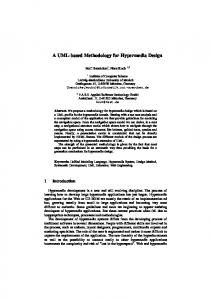
In section II, we will show a brief introduction to our design flow. In section III, we will show the supported UML diagram and its meanings. In section IV, we will show a new HDL syntax and its usage. In section V, we will show some educational examples. In section VI, we will conclude our paper. II. D ESIGN F LOW FOR FPGA DESIGNER The Figure 1 shows our LSI design flow. In this flow, we uses SystemC for architectural and RTL level simulation.
I. I NTRODUCTION
Architecture level modeling
UML is becoming major modeling language for software[1]. And, CASE tools which utilize UML are becoming popular among software engineers. We think that we can use UML tools even for hardware design for the requirement capture and the architectural refinements. In the other hand, hardware designers tend to use paper and pencils for their architectural design. Because popular modeling language such as VerilogHDL and/or VHDL are too poor for the architectural modeling. Recently, C based or SystemC based design tools are available, but the applicability is restricted and in many cases we must rewrite our design completely with RTL languages. In this paper we propose a digital system design methodology which applies UML class diagrams on hardware design. We will use UML tools to model hierarchical hardware modules. We defined some attributes and visibilities for this purpose. In this paper, we also propose an automatic skeleton generator for hardware description language from UML. It utilizes XMI (XML Meta data Interchange format)[2] as the input which is the standard interchange format for UML from OMG. Therefore, we can use any UML draw tools for software engineers which can export the UML diagram to XMI for designing our hardware. This process consists of two tools one will convert exported XMI to extended SFL (SFL: Structural Functional Language from PARTHENON society[3], we call the extended SFL as NSL), and the other will convert the NSL to SystemC or VerilogHDL or VHDL. Therefore, we can use SystemC for verification, and VerilogHDL for FPGA and/or ASIC implementation. Both tools are available for download from IP ARCH, Inc[4]. OMG proposed ”UML Profile for SoC[6]” for system on chips and/or system designs. It says, ”The components may be of digital, analog, or mixed-signal types.” We believe that logic LSI architects will feel difficulty applying them for REAL designs. Because the focus of the standard is too wide for many logic systems, and it is too complicated for logic LSI designers. We defined simple UML notation for logic LSI designers. It defines correspondence of UML to digital LSI modules. It is simple enough for LSI designers to start their design with UML, even if they have no experience with UML.
Sorawat Chivapreecha‡
UML SystemC
SystemC
UML2SFL Semi auto generate + manual entry
manual entry
prototype
NSL
Verification codes
sfl2vl Verification RTL
Auto generate
SystemC
Verilog
Verification FPGA
Fig. 1.
The NEW LSI Design Flow with UML, NSL and SystemC
We will capture the requirements of the target design with UML diagram such as use case diagrams as software people. In the architectural design process, we will produce architectural design diagram such as class diagrams, state charts or activity diagrams.. We will carry the architectural verification with these diagrams and writing SystemC programs. We will use a specialized class diagram for detailed representation of LSI which is described in section III in which we use explicit input or output or control terminals with arguments. We can translate this class diagram to NSL language with our ’UML2SFL’ tool. The NSL language will be described in section IV. We cannot write behavior of the module in class diagram, because UML standards does not have behavioral description in the class diagram. In our previous research[8], we used state diagrams to represent behavior. However, its representation is strongly depend on tools to draw the diagram because behavioral description of UML is not standard in OMG’s XMI, And many UML tools have quite different representation for them. Therefore, we terminated the support for behavioral generator, and we need to add hand written behavioral description to the obtained code by ourself. It remains for future standardization of behavioral meta data exchange of UML. We can translate the NSL, with the hand coded behavioral description, to RTL code of SystemC or VerilogHDL with our tool ’sfl2vl[5].’ Then we will be able to make an RTL simulation with SystemC to verify our design.
- 62 -