environment. Such a model may be obtained by a simulation of the manipulation tasks in virtual reality. Further, the possible transitions between the contact ...
2005 IEEE International Conference on Robotics & Automation (ICRA), Barcelona, April 18-22, 2005
Manipulation of Deformable Linear Objects: From Geometric Model Towards Program Generation Jürgen Acker and Dominik Henrich Lehrstuhl Angewandte Informatik III Fakultät für Mathematik, Physik und Angewandte Informatik Universität Bayreuth, D-95445 Bayreuth, Germany [Juergen.Acker | Dominik.Henrich] @ uni-bayreuth.de Abstract - This paper discusses the handling of deformable linear objects (DLOs), such as hoses, wires, or leaf springs in a polyhedral environment. It investigates the formulation of assembly or disassembly tasks based on contact states. The result is an approach that facilitates the automatic extraction of robot programs from demonstrations in virtual reality and provides a base for the parameterization of detection algorithms. For this purpose, a contact state model for the description of assembly or disassembly tasks of DLOs is presented. It is described how the contact states can be derived from a geometric model of both the DLO and the environment. Such a model may be obtained by a simulation of the manipulation tasks in virtual reality. Further, the possible transitions between the contact states are classified into general transition classes. Those transition classes enable the selection of algorithms to detect such contact state transitions. Index Terms - Keywords: Contact states, deformable linear objects, manipulation, assembly
I. INTRODUCTION In industrial assembly tasks, rigid as well as non-rigid objects must be handled. However, industrial robot systems work only with rigid objects. Ropes, wires, hoses, steel springs or other deformable linear objects (DLOs) are usually handled by human workers only. For robots, the main problem in handling DLOs is coping with inherent uncertainties concerning the exact shape of an individual DLO. Additionally, the shape of a DLO also changes during the manipulation process due to gravity and contact forces. The obvious approach is the use of sensors to compensate for these uncertainties. Often, research involving DLOs, e.g. [7], only investigates single tasks like “peg-in-hole” and it remains unclear how these special solutions can be applied to more general cases. Therefore, a systematic approach for manipulation of DLOs is needed. The manipulation of rigid objects has been studied for years. Thus, systematic approaches exist in this domain, such as [2] and [5], where assembly or disassembly tasks are described based on contact states. The transitions between contact states are carried out by robust and flexible routines (skills). Those skills encapsulate the programming-intensive sensor data processing and can be used for solving complex assembly or disassembly problems, like the disassembly of a valve [2]. Further, the description of manipulation tasks was employed for planning such manipulation tasks. Since contact states proved to be useful in the domain of rigid objects, [10] and especially [3] applied this approach to deformable objects. Both groups concentrated on DLOs but the representations differ. The contact state
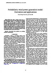
model in [3] regards only single contact points between a DLO and convex environment objects, whereas [10] uses a set of contact patterns and transitions between them for the purpose of planning manipulation tasks. In general, planning is a difficult task for computers, since it is NP-hard. Therefore, other methods have been considered, such as programming by demonstration. In the domain of manipulating deformable objects, [4] realizes a skill controller based on programming by demonstration in combination with contact states. The design strategy of this controller depends on a data profile generated by a human worker. The recorded sensor data profile is further processed to identify the control parameters. The mapping of the continuous data profile to contact states and discrete transitions respectively has to be done manually, according to [4]; this reveals two disadvantages of this approach. First, such a demonstration has to be carried out with the same sensors that are later used for the manipulation task. Second, a human is not only necessary for the demonstration but for the identification of control parameters as well. Therefore, in [6] the programming by demonstration paradigm is performed in virtual reality and the human worker uses a haptic input device to demonstrate the task. Fig. 1 shows the complete system concept, from the demonstration of the task to the sensor based detection of contact state transitions. The virtual reality covers the task simulation and portions of the contact state extraction. Here, the extraction is performed automatically based on the limited contact state model presented in [3]. The sensor based on-line part of this system was investigated in [9] and [1]. Task Simulation
Contact State Extraction
Program Generation
(t) a
NN N V/F V/F V/F V/F V/E N
N V/F
b
V/E
C
t
1 E
F
2
3 F:
4
E:
off-line on-line
Transition Recognition
Feature Selection
Makro Execution
L(a,b,c,d)
Transition( a,b,c,d, S ): N_V/G(M,F):
1 Fx + ...+ 6M z
REPEAT MoveS(M) Until Transition(a,b,c,d,S);
t
TransferTo(b); N_V/F(M 1,F); TransferTo(c); V/F_V/E (M2 ,E); M i : Direction of motion
t0
t
S = ( 1 , ..., 6)
Fig. 1 Illustration of the overall process for programming and execution of sensor-based robot programs taken from [6].
This papers covers the contact state extraction and program generation steps of the system shown in Fig. 1. We thereby refine and extend the contact state model from [3] to a polyhedral environment of convex and non-convex objects and to include multiple contacts. Further, we show how topological contact states can be extracted from the geometrical model used in virtual reality. This topological model is transferred to a more abstract discrete contact state model that provides a base for the program generation. In Section II, the underlying geometrical models of the environment and the DLO are described as used in virtual reality. Section III introduces the topological model that we derive from the geometrical model. The next step towards program generation is the transformation of the topological model to the contact state model in Section IV. In Section V the transitions between contact states are investigated. Based on Sections III through V, we describe a manipulation task as an example in Section VI. Finally, Section VII provides a summary and gives an overview of further research.
Each convex object is modelled as a set of surfaces. i) and one point For each surface F i the normal vector N(F P(F i) within the surface are given. All normal vectors point away from the object´s surface, as shown on the right in Fig. 2. Due to the geometric model of the ideal DLO, we postulate that two environment objects intersect if the smallest distance between both objects is less or equal to the diameter of the DLO. Recapitulating, the geometrical model contains all environmental objects and the exact shape of the DLO. Additionally, all angles and all distances are known in this model. III. TOPOLOGICAL CONTACT MODEL From the geometric model we can derive the topological model. This model describes the topological contact situation i.e. all contacts between the DLO and environmental objects. Thus, in this model the environment and the DLO are only well defined at contact zones (Fig. 3).
II. GEOMETRICAL MODEL AND BASIC ASSUMPTIONS Because the geometrical model is the most concrete and it is used in the virtual reality portion of the complete system (Fig. 1), we start from this point. First, we define every deformable object with a diameter much smaller than its length as “linear”. We assume elastic deformation and do not consider plastic or extensional deformation. Further, we assume torsion is negligible, thus we do not state it explicitly. In the ideal case, the diameter of the DLO is zero. Therefore, we model DLOs as a single curved line. More precisely, the DLO is modelled as a sen , where each point Pi is defined by quence of points P i i=0 its position vector pi. The number n of points is assumed to be high enough for a sufficient precision (Fig. 2, left). Therefore, n may depend on the shape of the DLO. The first point of the sequence is also called the start point (VS) and the last point is the end point (VE) of the DLO. Fur i of a given point Pi (1). ther, we define the DLO vector D =p −p D i i1 i
(1)
i can be used as the tangent along the DLO for Thus, D each point of th DLO. Now that we have described the geometric model of the DLO, we now describe the environment. We assume a polyhedral environment of rigid objects as in [3] but we extend the environment from convex objects only to include non-convex objects. Each non-convex object is split up into the smallest possible number of convex objects. P10 P8 P5
P1 P0
P6
P7
P9
P11
P12
F2 F3
P4 P3 P2
F4
F4
F5a
F3 F6
F5 F2
F1
F5b
F1
Fig. 2 Geometrical Models of DLO (left) and non-convex environment objects (right) and its decomposition into two convex objects.
Fig. 3 Geometrical model of a contact situation (left); and contact zones of the situation from the left which remain in the topological model (right).
In order to describe those contact zones, we first introduce some environment primitives EP. The first environment primitives are the surfaces of the environment objects, further called faces F i. Further, the intersection of of n directly adjacent faces F i, F j, ... F n belonging to the same convex object are denoted as F i F j ... F n. The intersection F i F j may be abbreviated as edge Ei,j and the intersection F i F j .. F n may be abbreviated as Vi, j, ..,n. Since the topological contact model is restricted to contact zones (Fig. 3), we introduce the empty object N representing empty space. For convenience, we also introduce the object Gz , representing the gripper of the robot. The annotated vector z represents the normal vector of the gripper and is parallel to the zaxis of the tool center point (TCP). Thus, the environment primitives are the set EP:={N, Gz, F i, Ei,j, Vi, j, ..., n}. Corresponding to the environment primitives, we introduce V and E as DLO primitives. The primitive vertex V is used for VS and VE. For all other points along the DLO, the primitive edge E is used. DLO primitives are indexed by their DLO vectors. Now let us define the different types of contacts in order to define a contact situation. A basic contact is a pair P/Q where P is a DLO primitive and Q is a DLO or an environment primitive. Since for assembly tasks contacts between DLOs and the environment are the most important, we will more closely examine on contacts between DLO and environment primitives. If one point of the DLO is in contact with more than one geometric primitive except N, the contact is called a multiple contact, otherwise it is a single contact. The basic contacts of a multiple contact are concatenated by the
operator “+”. The contact situation is now the ordered sequence of all single or multiple contacts from VS to VE (Fig. 4). Here, the contacts are concatenated with logical AND (^). If m adjacent points of the DLO Pi, Pi+1, .., Pi+m and (0