requirements using the natural language processing system. LOLITA,â Natural Language Engineering, vol. 2, no. 2, pp. 161â. 187, 1996. [2] C. Larman, Applying ...
Behavioral Model Generation from Use Cases Based on Ontology Mapping and GRASP Patterns Nurfauza Jali, Des Greer and Philip Hanna School of Electronics, Electrical Engineering & Computer Science Queen’s University Belfast Belfast BT7 1NN {njali01| des.greer| p.hanna}@qub.ac.uk Saeki et al.[4], Carasik et al. [6], Cockburn [7], Boyd [8] and Juristo et al.[9] have explored the use of language as a metaphorical basis (analogical source) for discovering the structure (syntax) of objects and object messages, and for the naming (semantics) of software components. Their work has focused on the production of UML static diagrams (e.g. Use Case diagram and Class diagram). Other tools such as NL-OOP[1], RECORD [10], CM-Builder [11], LIDA [12] and UCDA [13] also only generate static diagrams, probably because this is less complex than building dynamic diagrams. GOOAL [14], CIRCE[15], and a-Toucan [16] are tools that claim to produce UML sequence diagrams besides generating other UML diagrams (use case diagram, activity diagram and class diagram). Table 1.0 summarizes the types of UML diagrams produced from each of the research projects mentioned above. The tick () symbol represents diagrams that had been implemented in the existing research projects. All the tools investigated are able to identify attributes, objects and methods from requirements text for the production of UML diagrams. However, they require human intervention to interpret the correctly extracted annotation of OO concepts before building a particular diagram. The existing tools need to enhance their NLP system to produce high quality analyses by allowing for dependable deep semantic analysis and adequate syntactic analysis, in order to produce high quality diagrams. The ontology will be used to ensure that software engineers have a shared understanding of the problem domain with the stakeholders as well as to promote reusability.
Abstract— This paper contributes a new approach for developing UML software designs from Natural Language (NL), making use of a meta-domain oriented ontology, well established software design principles and Natural Language Processing (NLP) tools. In the approach described here, banks of grammatical rules are used to assign event flows from essential use cases. A domain specific ontology is also constructed, permitting semantic mapping between the NL input and the modeled domain. Rules based on the widely-used General Responsibility Assignment Software Principles (GRASP) are then applied to derive behavioral models. Keywords- Requirement Engineering, Ontology, Requirement Specification, Natural Language Processing, Software model, UML, Software Design Pattern
I.
INTRODUCTION
One of the biggest challenges in Requirement Engineering (RE) is managing changes. Requirements are most often written and communicated in Natural Language (NL)[1][2] but unfortunately moving from NL to software design is a difficult and time consuming process. The purpose of this work is to increase the efficiency of software development based on the automated transition from textual to a conceptual visualization of the dynamic software model. An approach is described, where starting with the text-based use-case specifications, objects inside the use-case specifications are elicited and object properties extraction is affected using an ontology representing the domain model. Eventually, behavior is modeled and visualized as Unified Modeling Language (UML) sequence diagrams. The next section provides an overview of related research. Section III gives a description of the problem under investigation. Section IV demonstrates the solution approach using a ‘Point of Sale’ illustration and the final section discusses the results obtained. II.
TABLE I.
CHECKLIST OF UML DIAGRAMS PRODUCED FROM EXISTING RESEARCH PROJECTS.
BACKGROUND
There is undoubtedly a challenge in translating a natural language description into usable software. NL descriptions of problem domains captured from the stakeholder are often complex, vague and ambiguous leading to multiple interpretations [3]. Saeki et al. [4], and Rupp [5] have analyzed the requirement specification document from a linguistic aspect.
In the production of sequence diagrams, various synthesis techniques were used to build these models from use case
324
system’s behavioral requirements by detailing event-driven threads. In this module, such a template will permit the user to clearly and succinctly input the important use case specification element(s). We have utilized the concept of an essential use case [22], where the use case form is split into user intentions and system responsibilities and target applications that can be specified using this form. In implementing this restriction, we reduce the probability of misinterpretations by an NLP system and at the same time ensure that the user has written the use case in a way that makes it possible to identify user actions and system responsibilities. Later this should help to reduce the need for human intervention. In realizing this, a set of rules in the use case content structure are introduced.
specification scenarios. Work by [17][18][19]were refereed and their approaches will be enhanced to meet the goal of building a precise dynamic model. III.
PROPOSED APPROACH
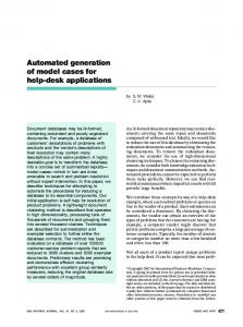
We propose an architecture for a toolset ‘Use Case specification to Sequence Diagrams’ (UC2SD) which allows us to produce UML sequence diagrams from the text requirements provided by the stakeholder(s). This architecture will focus on the modeling aspects of the process, largely where the end result is to generate diagrams and software code to represent the solution. Requirements analysis will involve an automated Natural Language Processing (NLP) process. In turn, the requirements analysis to design phase will involve the extraction of object model elements such as classes, attributes, methods and relationships derived from the NLP. The inclusion of knowledge in related domain ontologies will help to refine the object and properties candidates. In the software design and the implementation phases, these components will assist in building software models such as UML diagrams and software code. The data verification for each module will be evaluated by human experts. Data correction is a part the verification process. Thus we are aiming at design support rather than complete automation. Nonetheless, it is hoped that the NLP can handle the majority of the process in our approach. In what follows, we will describe the research justification for each module in the architecture, its role in achieving the research goal.
B. Natural Language Processing Module Liddy et al. [23] has defined Natural Language Processing or NLP as “a theoretically motivated range of computational techniques for analyzing and representing naturally occurring texts/speech at one or more levels of linguistic analysis for the purpose of achieving humanlike language processing for a variety of tasks or applications.” The NLP goal is to transform text information to some internal data model which synthesizes from a data form into a NL surface form [24]. In Linguistic analysis of NL text, Li et al. [3] have identified three main components: word-tagging; syntactic analysis; and semantic analysis. In the proposed architecture, the text will be processed in four stages: Lexical Analysis; Syntactic Text Analysis; Candidate Refinements; and Semantic Text Analysis. 2) Lexical Analysis This stage involves the text tokenization and lexical preprocessing of the input text. Before the Part-of-Speech (POS) tagging process, the input text from use case specification has to be tokenized. Part-of-Speech determines word type and the role a word plays in the phrase structure. This is where the phrase or text is split up into a set of labeled tokens (i.e.: nouns, verb, adjective, adverb, etc…) [21]. In this context, we are using Penn Treebank Tagset [25] as a default set of grammar rules for each tagged token.
Figure 1.
3) Syntactic Analysis Syntactic analysis involves determining the structure of the input text. A single sentence is typically the largest modeled structure within a portion of text, whilst the smallest modeled structures are the basic symbols (i.e. mostly words) within the input text. In contrast with lexical analysis, syntactic analysis takes into account the sentence structure, whereby each lexical token is assigned one or more Part-ofSpeech tags. By identifying domain dependent terminology, an initial attempt is made at this point to extract and build a domain model within this stage.
Architecture of Use Case specification to Sequence Diagrams (UC2SD)
A. Requirement Analysis Module 1) Text Requirement Acquisition At this stage, requirements having been elicited are written using specified template rules. By template rules, we mean the use of guidelines or approaches to follow in developing use case specifications descriptions from system requirements [20][21]. The use case is used to capture
325
and fulfilled by collaborating with other classes. This will be further described in the next module.
4) Candidates Refinement The output of POS tagging will tag a set of preliminary noun and verb phrase candidates. It may be that preliminary candidates are poorly defined and often not related to the problem domain. At this stage, the collected candidates can be further analyzed to discover details such as “What are the refined candidate classes?”, “What might be the attribute value?”, and “What kind of relationships hold between the classes?” The solution for these questions will be sought in an iterative manner. This would lead to more detailed and refined object properties which can then be an input to the production of behavioral models. Domain ontology analysis will facilitate the process of identifying the relevant candidate classes aside from the verification by human experts. In order to refine a preliminary candidate class to relevant classes, the results from the parser will be matched with the concepts and structures defined within the ontology which will be described in the Knowledge Representation Module, later. The algorithm to refine the candidate classes is listed below followed by the identification of attributes and methods.
5) Semantic Text Analysis In semantic text analysis, the sentence level syntactic text analysis will be combined with the semantic items identified within the ontology to map them onto Object Oriented elements, namely classes, attributes, methods and relationships among the classes. Here, a rule-based approach is followed for identifying actors, objects, class attributes, messages etc. Behavior of each object are identified using the Subject-Verb-Object (SVO) approach, based on a word order of a typical sentence pattern. The verb carries the action across to a target or receiver. To illustrate, the SVO approach can be applied to a use case sentence as follows: “a customer (subject) creates(verb) account(object)”. In particular, a set of syntactic rules is proposed to assist the software developer in writing and normalizing the use case specification. The behavior element written in the specification statements can be read by machines using this syntactic pattern matching. At this stage, the meaning and relationship of each sentence will be analyzed iteratively. The semantic checking is performed here to resolve ambiguities.
Step 1: Pre-Class identification i. Identify candidate classes from the common nouns (e.g. things, persons, places) ii. Identify candidate classes from nouns which follow the preposition ‘a’ or ‘the’ (e.g.: a sale, the customer) iii. Identify candidate classes from the ‘IsA’ relationship (instantiation and inheritance) e.g.: Credit card is a Payment type. Credit Card is a subclass of Payment Step 2: Attribute Identification i. Identify attributes from common nouns (e.g.: Class Person attributes are first name, last name, address etc…) ii. Identify attributes from adjectives. e.g.: sale line item with description, price and total. Class: sale line item Adjective: with Attribute: description, price and total iii. Identify attributes from the ‘HasA’ relationship (aggregation) e.g.: Payment has an amount. Step 3: Operation and Relationship Identification i. Identify the operation or method from action verbs (e.g.: calculate, start, enter) ii. Identify the relationship from static verbs which describe the association relationship. e.g.: Class Cashier works for Class Manager. Class System records the Class Sale Line Item.
C. Knowledge Representation In this module, the business domain knowledge is represented using suitable business ontology. We have selected the Business Management Ontologies (BMO) [26] as suitable for application to our case study. The current version of BMO has about 40 ontologies with around 1300 classes designed to allow the user to define private, public and collaborative business processes (using Business Process Modeling Notation). The content includes the data (instances) and definition where the higher-level ontology may import one or more lower level ontologies. This mapping process will be combined with the result from the candidate refinement stage using the POS-BMO ontology with the Protégé-OWL tool[27]. D. Object Oriented Design Module The output from the NLP processor will be used to generate sequence diagrams. Participating actors/ objects/ classes, messages/ methods and attributes are mapped respectively with nouns, verbs and adjectives and are then translated into UML sequence diagram constructs. At the beginning the system sequence diagram (SSD) will be generated,followed by the detailed sequence diagram. To move to detailed sequence diagrams, we must consider how objects collaborate with other objects to implement system operation. To achieve this we have applied the General Responsibility Assignment Software Principles (GRASP) [2], including Creator, Information Expert, Controller, Low Coupling and High Cohesion principles. These are used as follows: i. Creator – to determine who should be responsible for creating a specific object.
The outcomes for this process will produce a refined set of candidate classes and eliminate a number of irrelevant classes, which then might be acted as the attributes of the classes. The responsibility of a class is defined in its methods
326
ii. Information Expert - should be responsible for a responsibility based on it having the necessary data. iii. Controller - to determine which should be the first object to receive a message from an external actor iv. Low Coupling – used to choose between objects for responsibility assignment, based on interaction between objects v. High Cohesion – used to choose between objects for responsibility assignment and it measures how strongly related and focused are the responsibilities of each class. The goal of applying these principles is to identify object’s responsibility which in turn establishes its collaboration. E. Implementation Once the sequence diagrams have been generated, they can be checked and verified using human experts. Indeed, compilable code can be created from the sequence diagrams, if desired. This phase will not be discussed in this paper as the work is still in progress. IV.
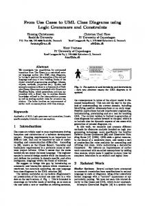
Figure 2.
UC2SD Automation of System Seqence Diagram (SSD) production
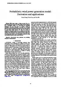
Figure 3.
System Seqence Diagram (SSD) of Process Sale use case generation
DEMONSTRATION AND ANALYSIS
A Use Case specification to Sequence Diagrams (UC2SD) generator was designed and constructed in order to demonstrate the approach. We used the processing resources that GATE [28] provides, which are made available in the form of plug-ins. GATE makes it possible to use the Java Annotations Pattern Engine (JAPE) transducer which provides a way to process text over specified annotations and to further identify patterns or entities in text. Input text is from the use case provided by the user, which needs to be tokenized and split into sentences. Each token (i.e. number, word, punctuation) is then assigned with Part-of-Speech (POS) tags where the grammars are based on Penn Treebank Tagset which applies the Hepple's Brill-style tagger This process is assisted by a morphological analyzer which involves lemmatization or word stemming. Next, the JAPE transducer will trigger the grammar rule to identify and annotate objects and messages from the given Syntactic Rules (SRs), discussed earlier. The JAPE syntaxes have been developed for all of the SRs. Thus, before the XML is produced, a frequency analysis step is carried out to produce frequency lists of overall word form. The selection of candidate classes are based upon the frequency of the nouns’ appearance and the result will then be verified by the user. This object property extraction is used to construct a System Sequence Diagram (SSD).The SSD is a sequence diagram that shows the event interaction between external actors with the system object. Figure 2 and 3 illustrate the Point of Sale (POS) system specification for process sale use case and the SSD generated. This SSD describes: (1) each method with a sequence number label above the arrow; (2) method parameters in brackets for each message; (3) message represented as solid arrows and returns represented as a dotted line arrow.
The SSD generation is a relatively straightforward task as it only involves the external actors, message flow and System object. However, a more detailed system design of SD can be derived with potential classes involving three common stereotypes (boundary, controller and entities). Thus, to construct a refined Sequence Diagram (rSD), we finalized the potential classes and determined responsibilities of objects within the system. To achieve this, we use the POS-BMO ontology to map the extracted object properties to appropriate objects. First it adds all the entity objects from preceding ontology analysis and then it transforms some individual messages on the GRASP rules. Finally it divides the System class into UI, Controller and Entity classes and as well adjusts the messages accordingly. All of this is currently done against a representation of the sequence diagrams in XML, via the Document Object Model (DOM) API.
327
In the beginning, we will focus on the three GRASP principles: Creator, Information Expert and Controller. In Creator, the pattern directs us to who should be responsible for creating a new instance of some class? According to Larman, the Creator principle applied to Process Sale use case is justified as follows:
b.
i. SystemRegister is responsible for creating the Sale object because the SystemRegister is used by the Cashier to ring in a new Sale. ii. The Sale object is responsible for creating the Payment object, as a payment is only being made when a sale is being made. Hence, the SystemRegister makes a Sale object which in turn makes a Payment object. The Information Expert principle guides us to assign responsibilities to objects where an object becomes an expert for a service if it has the ability or information to fulfil the obligations of that service. According to Larman, the Information Expert principle applied to the Process Sale use case is illustrated as follows: i. SystemRegister is the Information Expert for the following services: makeNewSale, enterItem, endSale, and makePayment, as it has the requisite information on hand to fulfil these obligations. ii. The Sale object is responsible for getTotal, makePayment, and makeLineItem. The picture should also include a call of makeLineItem to the SalesLineItem object. iii. The Product object is responsible for providing its own price, so it has a function called getPrice for this activity. Finally, Controller pattern handles system operation messages between the actor and first object in the domain layer. It is responsible for delegating tasks to other objects. We assumed that a controller pattern can be identified with the controller stereotype class, detailed earlier. In one of the heuristic [38] we can identify a controller class for each use case. Again the use of the Controller principle applied to Process Sale use case is described as follows: i. SystemRegister is the controller class which is responsible to delegate messages flow from Cashier as the actor class. ii. Before each message received by entity classes, SystemRegister will take control of the messages.
c.
There are three rules currently implemented. Creator, Controller and Information Expert. a. If there is a message in the SSD with a parameter whose name starts with the word "new", then insert immediately after it a message from the recipient of that message to the entity class named in the parameter. In the test use case, this rule matches
only the very first message in the SSD, "start(new sale)". From that message, the rule produces a message from the system (later split into System_UI and ProcessSaleHandler) to Sale. If a message is passed with a method named "record", and the parameter to that message is a class which is contained in another (based on the output of the ontology analysis), then replace that with two new messages: an add message from the sender of the "record" message to the container class, followed by a message from the container to the specified class. In the test use case, this rules matches only one message in the SSD, the "record(sale line item)" response from the system to the user. The result is the "addLineItem()" request from the system (later split into System_UI and ProcessSaleHandler) to Sale, followed by the message from Sale to SalesLineItem. Split the second class in the SSD into a UI class and a controller class (adjusting all the affected messages accordingly). If any of the entity classes has a name ending in "Controller" or "Handler" (from the ontology), then use it as the controller class, otherwise create the controller class by appending "_Controller" to the end of the name of the class being split. For the name of the UI class, use the name formed by appending "_UI" to the name of the class being split. In the test use case, this rule splits the "System" class into "System_UI" and "ProcessSaleHandler" (which is among the entities identified in the ontology analysis). Messages between "System" and "Cashier" are replaced by chains of two messages, passing through "System_UI". Messages between "System" and other entities are simply moved to ProcessSaleHandler.
Figure 4.
328
Refined Sequence Diagram (rSD)
[7]
Figure 5 illustrates the refined Sequence Diagram (rSD) that been generated from the tool based on the rules implemented. From the generated diagram it is clearly has similar result with the sample given by the expert (based on Larman’s book) because of the strong semantic support and rules constructed applied to the system tool.
[8] [9]
[10]
CONCLUSION AND FUTURE WORKS In automatically producing behavioral models from text the following tasks have been accomplished: A demonstration of linguistic algorithms to identify the proper object, classes, attributes relationships and so forth for building a System Sequence Diagram and Refined Sequence Diagram by applying rules based on GRASP Principles. A process has been developed for building an ontology to help improve the mapping process of words terms nouns/verbs etc.) toUML notations, particularly relating to behavior (objects/messages etc.). One of the limitations of this work is that, since ontology practice is still immature, it is hard to find comprehensive ontology resources. In order to refine the current ontology, it may be worth looking at how well BMO and GoodRelations [29] could be aligned with each other. In future work, we will further derive and formulate the remainder of the GRASP principles, particularly low coupling and high cohesion. While there still remain many challenges in deriving compilable code from use case specifications, the advances in NLP theory and tool support offer the possibility of moving closer to this goal.
[11]
[12]
[13]
[14] [15] [16] [17]
[18]
[19]
[20]
ACKNOWLEDGMENT
[21]
The authors gratefully acknowledge Ministry of Higher Education (MOHE) Malaysia, as part of the first author’s PhD studies scholarship.
[22] [23]
[24]
REFERENCES [1]
[2] [3] [4]
[5] [6]
L. Mich, “NL-OOPS: from natural language to object oriented requirements using the natural language processing system LOLITA,” Natural Language Engineering, vol. 2, no. 2, pp. 161– 187, 1996. C. Larman, Applying UML and Patterns, 2nd ed. Prentice Hall, 2001. K. Li, R. G. Dewar, and R.J.Pooley, “Object-Oriented Analysis Using Natural Language Processing,” in Linguistic Analysis, 2005. H. Saeki, Motoshi. Horai, Hisayuki. Enomoto, “Software development process from natural language specification,” Proc. 11th International Conference in Software Engineering - ICSE ’89, pp. 64–73, 1989. C. Rupp, “Requirements Templates — The Blueprint of your Requirement,” Requirement Engineering., 2004. Robert P Carasik, S. M. Johnson, D. A. Patterson, and G. A. Von Glahn, “Towards a Domain Description Grammar: An Application of Linguistic Semantics,” Engineering, vol. 15, no. 5, 1990.
[25]
[26] [27]
[28]
[29]
329
A. Cockburn, “Using natural language as a metaphoric base for OO.,” SIGPLAN OOPS, vol. 4, pp. 187–189, 1993. N. Boyd, “Using Natural Language in Software Development,” J. Object Oriented Program., 1999. N. Juristo, A. M. Moreno, and M. López, “How to Use Linguistic Instruments for Object-Oriented Analysis,” IEEE Software., no. June, pp. 80–89, 2000. J. Börstler, “User-Centered Requirements Engineering in REquirements COllection Reuse and Documentation (RECORD) An Overview,” in Proceedings Nordic Workshop on Programming Environment Research (NWPER’96), 1996, pp. 149–156. H. M. Harmain and R. Gaizauskas, “CM-Builder: an automated NLbased CASE tool,” Proc. ASE 2000. Fifteenth IEEE Internationa. Conference Automation Software Engineering, pp. 45–53, 2000. S. P. Overmyer, L. Benoit, and R. Owen, “Conceptual modeling through linguistic analysis using LIDA,” in Proceedings of the 23rd International Conference on Software Engineering (ICSE), 2001, pp. 401–410. K. Subramaniam, D. Liu, B. H. Far, and Armin Eberlein, “UCDA: Use Case Driven Development Assistant Tool for Class Model Generation,” in The Sixteenth International Conference on Software Engineering and Knowledge Engineering (SEKE’04), 2004, pp. 1–6. H. G. Perez-gonzalez and J. K. Kalita, “GOOAL: A Graphic Object Oriented Analysis Laboratory,” in OOPSLA’02, 2002, pp. 38–39. V. Ambriola and V. Gervasi, “The Circe approach to the systematic analysis of NL requirements,” 2003. T. Yue, L. C. Briand, and Y. Labiche, “Automatically Deriving UML Sequence Diagrams from Use Cases,” Norway, 2010. Z. Ding and M. Jiang, “Model Driven Synthesis of Behavioral Models,” Informatics Control. Autom. Robot., vol. 132, pp. 713–717, 2011. C. Damas, B. Lambeau, P. Dupont, and A. Van Lamsweerde, “Generating Annotated Behavior Models from End-User Scenarios,” IEEE Trans. Softw. Eng., vol. 31, no. 12, pp. 1056–1073, 2005. Z. Ding and M. Jiang, “Model Driven Synthesis of Behavioral Models from Textual Use Cases,” in Informatics in Control, Automation and Robotics, Springer, 2011, pp. 713–717. M. G. Ilieva and O. Ormandjieva, “Models Derived from Automatically Analyzed Textual User Requirements,” Fourth International Conference Software Engineering, pp. 13–21, 2006. L. Kof, “Text Analysis for Requirements Engineering,” Technischen Universitat Munchen, 2005. E. T. Robert Biddle, James Noble, “Essential Use Cases and Reponsiblity in Object Oriented Development,” 2001. E. D. Liddy, E. Hovy, J. Lin, J. Prager, D. Radev, L. Vanderwende, and R. Weischedel., Natural Language Processing, 2nd ed. Marcel Decker, Inc., 2003, pp. 2126–2136. E. Brill and R. J. Mooney, “An Overview of Empirical Natural Language Processing,” AI Magazine, vol. 18, no. 4, pp. 13–24, 1997. C. D. Manning, “Part-of-Speech Tagging from 97 % to 100 %: Is It Time for Some Linguistics ?,” in 12th International Conference, Computational Linguistics and Intelligent Text Processing, (CICLing 2011), 2011, pp. 171–189. Jenz and P. Gmbh, “Business Management Ontology ( BMO ) Version 1.0,” Germany, 2004. “The Protege Ontology Editor and Knowledge Acquisition System,” Research, Stanford Center for Biomedical Informatics, 2010. [Online]. Available: http://protege.stanford.edu/overview/protegeowl.html. [Accessed: 02-Nov-2011]. K. Bontcheva, V. Tablan, D. Maynard, and H. Cunningham, “Evolving GATE to meet new challenges in language engineering,” Natural Language Engineering, vol. 10, no. 3–4, pp. 349–373, 2004. M. Hepp, “GoodRelations : An Ontology for Describing Web Offerings Final Version The GoodRelations Ontology,” Information System Journal, p. 105, 2008.