It has been shown in Mar89b], BE90] that the class of purely DI circuits is very limited. ... Note that if B wins the race, output of D will remain at 1 and the nal (stable) state of the ... software process. A DI circuit as a program has the following ..... The hats denote vectors (multiple assignment), C a guard, ^f a vector of functions.
From Parallel Programs To Asynchronous VLSI Priyadarsan Patra Department of Computer Sciences The University of Texas at Austin Austin, TX 78712 abstract
This paper motivates and discusses the issues involved in design of asynchronous circuits. Starting from a conventional engineering approach, several extant formal methodologies for design, veri cation and analysis of asynchronous circuits (data- ow networks) are presented and their salient points explored. Relationships among competing theories are drawn. A preliminary approach to map UNITY programs into asynchronous logic circuits is attempted.
i
Contents
1 Introduction
1
1.1 Why Asynchronous Systems? : : : : : : : : : : : : : : : : : : 2 1.2 Subclasses of Asynchronous Systems : : : : : : : : : : : : : : 3
2 Some Synthesis and Veri cation Techniques 2.1 An Example Design : : : : : : : : : : : : : 2.2 Trace Theory and DI Design : : : : : : : : 2.2.1 Specifying the QEC : : : : : : : : : 2.2.2 Characterization of DI : : : : : : : 2.2.3 Implementing the QEC : : : : : : : 2.3 Martin's Method : : : : : : : : : : : : : : 2.3.1 Process Decomposition : : : : : : : 2.3.2 Handshaking Expansion : : : : : : 2.3.3 Production-Rule Expansion : : : : 2.3.4 Operator Reduction : : : : : : : : : 2.3.5 How is delay-insensitivity achieved 2.3.6 Some remarks : : : : : : : : : : : : 2.4 \Synchronized Transitions" : : : : : : : : 2.5 Signal Transition Graphs : : : : : : : : : : 2.6 Dill's Veri cation Technique : : : : : : : :
3 UNITY Formalism for DI design ? 4 Concluding Remarks
ii
: : : : : : : : : : : : : : :
: : : : : : : : : : : : : : :
: : : : : : : : : : : : : : :
: : : : : : : : : : : : : : :
: : : : : : : : : : : : : : :
: : : : : : : : : : : : : : :
: : : : : : : : : : : : : : :
: : : : : : : : : : : : : : :
: : : : : : : : : : : : : : :
: : : : : : : : : : : : : : :
: : : : : : : : : : : : : : :
5
6 7 8 9 11 12 13 14 15 17 18 19 19 20 21
22 25
Priyadarsan Patra
1
1 Introduction Advances in Integrated Circuit (IC) technology have often outpaced those in the area of hardware design & veri cation methods, although the latter's development itself has been impressive. The enormity of the task to specify, design, optimize, verify and test hardware of high complexity and density has led the way to various formal approaches, particularly the ones inspired by software methodologies. This paper brie y describes several speci cation/design disciplines for asynchronous circuits, completely ignoring their synchronous counterparts. Nonetheless, we give some motivations for such a one-sided theme. First though, we de ne certain \terms of the trade". A system is an \indivisible" hardware device (software process) or a nite network of subsystems, with interconnected input and output terminals (\ports"). A subsystem is itself a system. Input terminals are connected to output terminals via directed \wires" (or channels). A well-formed system has no input terminal unconnected (\dangling") and no two output terminals connected together. A system is synchronous with respect to computation if its constituent subsystems perform one unit of computation at a step de ned system-wide, i.e. a subsystem performs its N+1st step only after all the sister subsystems have performed their respective Nth steps. If the subsystems' computational speeds are not constrained in any way (other than through communication), then the system is asynchronous with respect to computation. A system is synchronous with respect to communication if the subsystems may have independent computation speeds but are synchronized by a communication step where the communicating parties reach some common control point and some or no data is interchanged among them. In other words, the cooperating subsystems \rendezvous" and their communication (which is a mere synchronization when no data is transmitted) is said to \complete" simultaneously, from when on they proceed freely until the next communication action. Note that the communication is through a zero-sized bu�er. A system with unbounded input or output bu�ers for the communicating subsystems is said to be asynchronous with respect to communication. A subsystem with no input stays idle until input arrives. A non-blocking asynchronous system is that where a subsystem does not
Priyadarsan Patra
2
have to block/wait upon reading an empty input bu�er. In the rest of the paper, by asynchronous we mean \asynchronous with respect to computation but synchronous communication-wise" and the design methodologies push back delay assumptions (except that delays are nite) to a level of implementation as low as possible. Generalization to other types of `asynchrony' is out of scope of this paper. A delay-insensitive (DI) system is one whose speci ed functional behavior is independent of any nite delays in the subsystems or in the wires interconnecting the subsystems' terminals. DI signalling refers to the protocol where a system does not output data on a channel until the receiver is ready. A voltage signal is said to be in de ned LOW state if its value is at or below vl and to be in de ned HIGH state if its value is at or above vh with vl < vh; it's unde ned otherwise. A voltage signal v is monotonic if and only if (t standing for time),
�v=�t � 0 when tl � t � th and tl < th �v=�t � 0 when th � t � tl and th < tl where tl and th are two consecutive time instants when signal v enters or leaves a de ned state. A circuit is monotonic if all the signals generated in the circuit are monotonic when monotonic inputs are applied to it. A handshake is an essential communication protocol between two asynchronous circuits for synchronization or data transfer done with the help of a request and an acknowledge wire. In 2-phase handshake, the initiating circuit raises the request signal, upon observing which the receiving circuit raises its acknowledge signal to complete the protocol. In a 4-phase handshake, the initiator raises the `request' signal, then the responder raises the `acknowledge' signal, then the initiator lowers the `request' and nally, responder lowers the `acknowledge' to complete the protocol. Before and after the communication, all signals are LOW.
1.1 Why Asynchronous Systems?
Some advantages of asynchronous circuits over synchronous ones are listed below:
Priyadarsan Patra
3
� Functional correctness of circuit is independent of variations in element � � � � �
delays caused by physical environment or by decrease in feature size (which increases di�usion delay.) As such, layout and routing become much less daunting. Clock distribution and skew problems disappear with the (global) clock. Hardware runs as fast as the computational dependency and input rate allow. Logic hazards, races, and synchronization failure due to metastability become non-problems. It facilitates separation of concerns between functional and physical aspects of design (as in discrete Logic VS device Physics, Topology(connectivity) VS Geometry(distance), and Partial Sequence Orders VS continuous Time.) Circuits are parsimonious in energy usage when quiescent (not computing).
1.2 Subclasses of Asynchronous Systems
It has been shown in [Mar89b], [BE90] that the class of purely DI circuits is very limited. Some researchers have assumed existence of some basic delayinsensitive components to synthesize DI circuits while others make use of one of three primary compromises applied to the delay assumptions [Ebe89]. These three compromises lead to the following types of systems : speed-independent A system whose functional behavior is independent of any delay in the subsystems with the assumption that the interconnection wires have zero delay and that the output changes instantaneously [mb559], [Dil89]. self-timed A system [Sei80]whose inputs obey certain \domain" constraints on their occurrence and whose outputs satisfy certain \functional" constraints on their availability. Inputs (outputs) of a component change from all-unde ned state to all-de ned state and vice versa, as if simulating a local clock for self-timing. Additionally, the system may be
4
Priyadarsan Patra
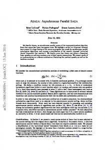
divided into \equi-potential" regions such that delay in a wire within an equi-potential is assumed to be negligible while delay in wires between parts in di�erent \potentials" is assumed arbitrary. quasi-delay-insensitive This type of system may contain isochronic forks. A fork is isochronic if we can assume that the di�erence in the delays between its fanout branches is negligible compared to the delay in the subsystems these branches connect to ([Mar89b]). Self-timed systems assume fundamental-mode operation while the other two systems above rely on input-output mode. To see that speed-independence is a weaker concept than delay-insensitivity consider the circuit given in gure 1: A C B
D
Figure 1: Speed-independence VS Delay-insensitivity Suppose there are no wire delays (as assumed for speed-independent circuits), but gates have arbitrary, bounded (inertial) delays. Consider the global stable state (A=1, B=0, C=1, D=1) for the gate circuit. Suppose the only circuit input A transits to the binary value 0 making gates B and C unstable concurrently. The gates B and C are said to be in a race. The outcome of the race (i.e. which one completes rst) will determine the nal state of the circuit as we shall see. If the delay in gate B is su�ciently large, gate C \wins" and transits to 0 which in turn makes gate D produce a 0. After gate B reacts, C eventually outputs a 1. At this point, D is already in the stable state 0 and the circuit is said to have settled at the state (0, 1, 1, 0). Note that if B wins the race, output of D will remain at 1 and the nal (stable) state of the circuit will be (0, 1, 1, 1). This illustrates that the circuit is not speed-independent with respect to the input transition 1 to 0 in initial state (1, 0, 1, 1). Next, assume the initial stable state to be (0, 1, 1, 1) and the input transits to a 1. The reader will see that the only nal (stable) state reachable is (1, 0, 1, 1) no matter what the delays in the gates are and hence the circuit
Priyadarsan Patra
5
is speed-independent with respect to this transition. However, suppose the wires also have arbitrary delays, in particular, the wire from input terminal A to gate C has su�ciently larger delay than the combined delay of the inverter and wire from A to gate C. In this case, it's possible for gate D to detect the transient transition of gate C to 0 and consequently gate D could stabilize to the value 0, thereby the circuit ending up in the stable state (1, 0, 1, 0). This points out that the wire delays could change the functional behavior of a circuit and hence pure delay-insensitivity is a stronger concept than speed-independence. Actual hardware gates have di�ering levels of threshold for activation. Therefor a voltage signal that may be viewed as a logical 1 by one gate, may not yet be a 1 to another. This necessitates the assumption of `instantaneous output transition' in speed-independence theory. Because otherwise, two gates reading two di�erent branches of a fork might see two inconsistent values at the same time making the assumptions of speed-independence theory invalid. (This is roughly similar to what happens when arbitrary wire delays in branches of a fork are permitted.)
2 Some Synthesis and Veri cation Techniques Conventional design methods for asynchronous sequential circuits usually assume one of the following modes of operating the circuit : 1. Fundamental Mode where the inputs to a system do not change until the system has reached a stable state. 2. Input-Output Mode where the inputs are allowed to change once some \expected" event (change) is seen on an output of the system. Unfortunately, these methods do not have su�cient theoretical underpinning besides often making unrealistic delay assumptions. Ivan Sutherland, Chuck Seitz, Charles Molnar, Alain Martin, and researchers at Eindhoven and others have made a convincing case for asynchronous designs by developing the formalism and mathematics and sometimes by implementing large systems. In this paper, we brie y mention synthesis techniques developed by Udding [Udd86], Snepscheut [Sne85], Chu [Chu87], Ebergen [Ebe89], and Staunstrup [SR89], and veri cation methods of Dill [Dil89].
Priyadarsan Patra
6
As an abstract model of VLSI, a hardware system can be thought of as an interconnection of chips which consist of pads (for I/O) and switches (transistors) with wires forming connections among them. Our aim in circuit design is to separate the issue of functional design from timing concerns, layout, routing, process engineering, material physics and such. A reactive, concurrent, distributed process suits well as a model for the goal to design VLSI except for the lack of atomicity of operations and discreteness of values present in a software process. A DI circuit as a program has the following important features: � only sequencing of actions, not timing is of concern at higher design levels � a set of elements communicating with each other, and reacting to the environment � absence of explicit control of computation � no dynamic creation or destruction (the program has no dynamic data structures) � state variables are represented by wires
2.1 An Example Design
Bu�ers are very useful abstractions for composing multiple processes and `Producer-Consumer' is a well-known paradigm for it. We wish to design a bounded bu�er that possibly serves as a `glue' between two computing units (or processes). In engineering lore, it's called a pipeline or queue. Size, input/output speci cation, I/O response, etc. are among its speci cation parameters. Even though a full- edged queue embodies control, data path, and processing logic, in this paper, we will illustrate some design methodologies by specifying and implementing only the controller for a QE to be henceforth called a QEC. Each such design technique directly transforms a \well-enough-re ned" speci cation into a gate-network of components taken from a given repertoire (e.g. [Sut89] uses event logic gates). A sequential algorithm for a 1-place bu�er (QE) might be:
Priyadarsan Patra
7
Initially QE is \empty" Loop-for-ever Wait for signal from \left" notifying availability of data Accept input data from left Inform the QE (or environment) to the \right" that data is available Pass data to right when the controller on the right is ready End-of-loop
2.2 Trace Theory and DI Design
Trace Structures were de ned to provide a more expressive language than the conventional regular languages for specifying nite automatons. A directed trace structure1 R is a triple < I; O; T > where I and O denote the input & the output alphabets, respectively. T � (I [ O)� is the trace set. An alphabet is a set of symbols; a trace is a sequence of symbols; a trace set is a set of traces. A trace structure is regular if its trace set is a regular set. In a mechanistic interpretation of traces, the symbols in input/output alphabets correspond to transitions (communication events) on circuit's input/output nodes, and a trace to an allowable sequence of communication events a system may \perform", i.e. a computation of the circuit. A regular command is a succinct representation of a regular directed trace structure. Commands are de ned inductively as follows. The atomic commands �, x?, x!, !x? stand for < �; �; f�g >, < fxg; �; fxg >, < �; fxg; fxg > and < fxg; fxg; fxg >, respectively. Let C:i, C:o, C:a, C:t denote the input alphabet, output alphabet, union of both input and output alphabets, and trace set of a trace structure represented by command C. Let A be an arbitrary alphabet. The operations on commands to obtain new ones are de ned below: Catenation C 0; C 1 = < C 0:i [ C 1:i; C 0:o [ C 1:o; (C 0:t)(C 1:t) > Union C 0jC 1 = < C 0:i [ C 1:i; C 0:o [ C 1:o; C 0:t [ C 1:t > Repetition [C] = < C:i; C:o; (C:t)� > Projection C # A = < C:i \ A; C:o \ A; fs # A j s 2 C:tg > Weave C 0kC 1 = < C 0:i [ C 1:i; C 0:o [ C 1:o; fs 2 (C 0:a [ C 1:a)� j s # C 0:a 2 C 0:t ^ s # C 1:a 2 C 1:tg > PrefixClosure pref C = < C:i; C:o; fs j (9t :: st 2 C:t)g > 1
\directed" because its symbols signify signal direction, i.e., input or output or both
Priyadarsan Patra
8
Pre x-closure operation legalizes all pre xes of a trace to be possible re ecting the \real-world" fact that for a sequence of actions to occur all its pre xes must occur before hand. Projection provides for ltering away any signals/variables internal to a system, perhaps leaving out only the transitions that are visible from its environment. Weave of two trace structures allows us to express parallelism and non-determinism among the automatons they describe, and also provides for synchronization via common symbols (actions). More details of trace theory may be found in [Udd86], [Sne85] and [Ebe89].
2.2.1 Specifying the QEC
Here we give a representation of a QEC in Ebergen's notation [Ebe89] and discuss its design and implementation in light of approaches taken by the above three authors. The darkened box in gure 2 represents a 1bit QEC which may be thought of as two automatons/processes with one responsible to obtain data from the producer on the left and the other for supplying data to the consumer on the right. Assuming 2-phase handshake2, the command for the \left" nite-state automaton (fsm) with bu�er initially \empty" is pref [li?; lo!] and the command for the \right" fsm with bu�er \full" initially is pref [ro!; ri?].3 But, we need synchronization between these independent automatons so that the consumer can take data only when the bu�er is \full" and the producer can put data only when the bu�er is \empty". There are several choices for such synchronization giving rise to several designs: CommandForLeftFsm CommandForRightFsm Comment pref [li?; !x?; !y?; lo!] pref [!x?; ro!; ri?; !y?] late return & sequential pref [li?; lo!; !x?; !y?] pref [!x?; ro!; ri?; !y?] quick return & sequential pref [li?; !x?; lo!] pref [!x?; ro!; ri?] quick return & concurrent In the above, \quick-return" refers to the fact that the producer's request signal is acknowledged immediately after the bu�er accepts the data { this perhaps allows the producer to start making data soon. \Late-return" means the producer is acknowledged only after the data taken into bu�er is, in Only a matching pair of request and acknowledgement constitute a data transfer. The x? denotes waiting for input transition and x! denotes generation of an output transition on x in the tradition of CSP [Hoa78]. 2 3
9
Priyadarsan Patra
ri?
li?
C
q?
p! lo!
ro!
Figure 2: A QEC with its implementation shown \encased" by its interface turn, removed by the consumer. \Concurrent" as opposed to \sequential" in the comments above means the communication events in the automatons overlap to some degree thereby probably providing speed. x and y are internal symbols for synchronization. We will consider the third speci cation. The command describing the external communication of the two \co-operating" fsm's is C = (pref [li?; !x?; lo!]kpref [!x?; ro!; ri?]) # fli; lo; ri; rog.
2.2.2 Characterization of DI
Several authors [MFR85], [Udd86], [Ebe89], [Dil89] and [JJH90] give equivalent de nitions of DI signalling. Udding [Udd86] proved four necessary and su�cient properties for a circuit to be delay-insensitive, we formulate them below: For any trace structure < I; O; T > of a DI system the following conditions apply,
Absence of Computation Interference h8s; t; a; b; c : s; t 2 T ^ a; b 2 I ^ c 2 O :: sactb 2 T ^ scat 2 T ) scatb 2 T i
This means, a component won't produce an output for another component as long as the latter is not in a state to accept it. Usually the
Priyadarsan Patra
10
input transitions occur if certain output transitions have occurred and vice versa in the so-called input-output mode of operation. For example, a circuit output could serve as an acknowledgement of some previous input transition and/or as a \go-ahead signal" to the environment to produce the next input. The formula above roughly states that if we assume no causal relationship between input event a and output event b then any valid extension of computation sac must also be a valid extension of computation sca.
Absence of Transmission Interference h8s; a : s 2 T ^ a 2 I [ O :: s 2 T ) :(saa 2 T )i
Informally, this property rules out the situation where two consecutive transitions on an input line without any intervening output transitions is possible. This is a practical concern, because two rapid successive transitions on a wire may interfere with each other electrically and lead to \misreading" by the receiving component. If the two transitions cancel each other, none of them may be seen and hence acknowledged by the receiver.
Independence From Relative Wire-Delays h8s; t; a; b : s; t 2 T ^ (a; b 2 I _ a; b 2 O) :: sabt 2 T � sbat 2 T i
This means that if \a?; b?" is a segment in a trace, then \b?; a?" must also be a segment in some trace. This captures the fact that if two consecutive inputs arrive at a system S in some order without an intervening output, the system cannot tell their time precedence (and hence, act di�erently).
Proper Arbitration h8s; a; b : s 2 T ^ ((a 2 I ^ b 2 O) _ (a 2 O ^ b 2 I )) :: sa 2 T ^ sb 2 T ) sab 2 T i
Proper Arbitration implies that a DI circuit cannot have an arbiter for choosing between an input event and an output event. If, for example, the system's arbiter rejects an input but lets an output generated, then the environment fails to know about the decision immediately (because of wire delays in output line) and hence end up generating a follow-up
Priyadarsan Patra
11
input leading to choking because the system is not ready to accept it. Such a possibility is ruled out by this last condition.
2.2.3 Implementing the QEC
Ebergen gives a very general (albeit non-optimal) algorithm for syntaxdirected translation of speci cations, satisfying a particular syntax, into DI circuits. The approach is based on three ideas, namely, decomposition, substitution and separation theorems.4 A decomposition of a command (or its corresponding circuit) allows it to be described as a set of simpler commands (connected components). A decomposition operation gives a network of components that is free of computation interference when composed with its environment. Of course, the network also has to be well-formed and the joint communication behavior of the components must be same as speci ed by the command being decomposed. If a decomposition is possible, the connection of the components from the decomposition form a speed-independent circuit. Realizing that command C is equivalent to command pref (li?; [(lo!; li?)k(ro!; ri?]), we may consider the following decomposition of C (p and q below are internal symbols): C ! (C1; C2; C3; C4) where C1 = pref [p?; lo!], C2 = pref [p?; ro!], C3 = pref [q!; ri?] and C4 = pref [li?kq?; p!]. The environment of C is C0 de ned to be the command C with its input and output alphabets swapped 5, i.e. C0 = (pref [li!; !x?; lo?]kpref [!x?; ro?; ri!]) # fli; lo; ri; rog. For an algorithm to check for freedom of computation-interference in any closed system of components and environment, see under \Dill's Veri cation Technique". The closed system of (C0; C1; C2; C3; C4) can be shown to have this property and the trace set of the decomposition (C1; C2; C3; C4) with internal symbols projected away is same as that of C . To guarantee delay-insensitivity, a DI decomposition has to be performed so that the components obey DI signalling, i.e., the network has no computationFor this paper, its presentation is out of scope. An input to the circuit is an output of the environment and vice versa. The environment is expected to produce outputs to extend the computation at the interface only to allowed traces. 4 5
12
Priyadarsan Patra
interference even when arbitrary wire delays are added at the common \boundaries" of the components. A DI component is delay-insensitive by construction. A network of DI components is guaranteed to be delay-insensitive. In the above, C1 and C2 describe two wires. C3 is a wire (ri; q) with an inverter at its output end so that initially when its input is LOW its output is HIGH thereby mimicing generation of an endogenous output event (transition) before any input or output event occurs on the wire. C4 describes communication behavior of a C-element with inputs li and q and the output p. It turns out all the three kinds of components mentioned above are DI and hence our decomposition is DI. The implementation of the DI circuit of QEC is given inside the shaded box in gure 2.
2.3 Martin's Method
Martin has developed a small language based on Hoare's CSP and Dijkstra's guarded commands to express algorithmically a circuit one wants to build. One might prove correctness and some other properties of such a program under CSP framework but Martin's method only provides ways to re ne (transform into more concrete form) this program while preserving the required semantics to nally produce a DI circuit. Hardware handshaking techniques are exploited to implement CSP's synchronous communication mechanism (which is required to complete simultaneously for both the communicating parties) by a simple rede nition of \completion" [Mar89b]. There are four stages of transformation of the initial speci cation program which lead to a DI network of gates. An overview of Martin's language (incomplete):
� All variables are boolean. � Atomic commands x" and x# stand for assignments x := true and x := false, respectively. � The execution of the selection command [G1 ! S1 : : : G ! S ], n
n
where G1 through Gn are boolean expressions (guards) and S1 through Sn are statements ( also called program-parts or commands), amounts to execution of an arbitrary Si whose guard Gi holds. If no guard holds, the execution of the selection command suspends until (G1 _ : : : _ Gn ) holds.
13
Priyadarsan Patra
� The execution of the repetition command ?[G1 ! S1 : : : G ! S ], n
� � � � � �
n
is tantamount to repeatedly selecting an arbitrary statement Si, when Gi holds, for execution. If none of the guards hold, the repetition terminates. S ; R is the command for sequential composition of commands S and R. C � D stand for simultaneous execution of commands C and D which might represent a synchronization action on a channel (C; D). [G], where G is boolean, stands for \wait until G holds" and is equivalent to [G ! skip]. ?[S ] stands for \repeat statement S for ever" and is equivalent to ?[true ! S ]. `k' is the operator for concurrent composition of commands. Each constituent command is called a process. L?x and R!x denote reading of data into variable x from channel L and writing data in x to the channel R, respectively.
For illustration of this method, consider the QEC program ?[L ; R] derived straightforward from the 1-bit bu�er program ?[L?x ; R!x]. Composition between adjacent QE's is established by sharing of variables (shared channels/wires in circuit) such that a variable that is an input to a QE is an output from the (immediately) previous QE.
2.3.1 Process Decomposition
A program is a concurrent composition of processes. Process decomposition is the operation of replacing a process with an equivalent set of simpler concurrent processes (i.e. concurrent program parts) such that right-hand side of guarded command is reduced to simple assignments and communication actions. This is done by introducing an internal channel between the process being simpli ed and a newly created process that acts like a procedure called in a sequential program. For example, the above control program may be process-decomposed into two concurrent processes :
Priyadarsan Patra
14
?[C ; R] k ? [[D ! L; D]] Let, p1 � ?[D ; R] and p2 � ?[[D ! L; D]] Here, the new process p2 makes use of a probe D ([Mar89b]) to communicate with the process p1. Probes are used to test if communication on the other side of a channel has been initiated which makes it possible to avoid blocking and to implement fairness in selection. Synchronization between p1 and p2 is done via the newly introduced channel (C; D) where the port C is in p1 and D in p2. In contrast to a data exchange, a `procedure gets executed by p2' during synchronization. Note that no true concurrency is added this way because p2 executes (the program-part L) only when p1 is waiting but the original process was simpli ed for implementation. A mechanistic interpretation of the commands above is that p2 executes L when p1 has initiated an action C on the channel (C; D). The synchronization completes when D, the matching communication action, is executed by p2.
2.3.2 Handshaking Expansion
Martin uses 4-phase handshaking to implement the \bullet" operator for synchronization on a channel. A channel (C; D) is implemented with two wires < co; di > and < do ; ci > | the request and acknowledge wires. (The two wires are also a good implementation for 1bit-data transfer as \double-rail encoding" comes in handy { it can represent invalid data and no-data states along with zero and one.) The wires model delay between the boundaries of the two communicating systems. All communications are chosen to obey a 4-phase (Return-to-Zero) protocol. While Ebergen and others use 2-phase6 , Martin's method seems to favor 4-phase handshake because it allows greater
exibility in manipulating/reordering atomic actions without the need for checking the state usually required in a 2-phase protocol and yet the penalty to reset the signals is minimal. An active party is the subsystem that initiates communication by raising its end of the request wire. The receiver of the request signal is the passive party of the channel. An active communication C on channel (C; D) is reduced to the sequence of 4 elementary actions: co " ; [ci] ; co # ; [:ci]. The matching communication action D which must be passive is the sequence [di] ; do " ; [:di] ; do #. The probe C is implemented as [di]. 6
Also called transition signalling
Priyadarsan Patra
15
Process p1 is \handshake-expanded" so that communication on (C; D) is necessarily active as p2 `probes' the channel. Since action R was originally supposed to be initiated by p1, it also starts an active protocol. Thus, p1 � ?[co " ; [ci] ; co # ; [:ci] ; [ro " ; [ri] ; ro # ; [:ri]] P2 which is passive on both actions D & L, expands to: ?[[di] ; [li] ; lo " ; [:li] ; lo # ; do " ; [:di] ; do #] A `wait-action' such as [:w] denotes wait by the process for the environment to supply a down transition on input wire w, while a `response-action' x" is generation of an up transition on output wire x by the process itself.
2.3.3 Production-Rule Expansion
This step is most di�cult and yet most interesting as it o�ers many choices for implementation. A Production Rule (PR) is of the form G 7! S where G is a boolean expression and S is a set of concurrent transitions (responseactions). A Production Rules Set (PRS) is a canonical representation of a concurrent composition of a set of PR's which are thought to be `active' all the time with no explicit control on their \ ring" (which re ects the reactive nature of hardware). In this step, each process is further massaged into a form amenable to compilation into a PRS. The result of this step is a union of the PRS's corresponding to all the processes of the program. The strategy to enforce the sequential order of atomic actions within a process and any needed mutual exclusion among con icting processes (so as to implement the semantics of the program) is to provide suitably strong guards for activating the responseactions (PRs). Speci cally, the sequence operator ; needs to be implemented. But observe that the sequence operator between two wait actions need not and should not be enforced as those are inputs to a DI component and their order cannot be predicted because of arbitrary relative delays in connection wires (Udding's 3rd DI condition). A guard for a response-action is derived by AND-ing some initial conditions and variables ( actually, literals) that are true after ring of the response-action immediately preceding it (see [Mar89a] for an algorithm.) For instance, the do " response-action of process p2 could be guarded by the
Priyadarsan Patra
16
guard :li derived from the only immediately-preceding wait-action [:li]. :li is guaranteed to be true at this point because lo is not lowered yet and the environment is assumed to follow 4-phase handshake. But it's not strong enough because li is LOW before the rst l ? action begins and after all 4 l ? actions complete and hence we need extra strength in the guard to be able to raise do at appropriate time in the p2's action sequence. Often following strategies are necessary to obtain just enough strong : Introduce internal state variables to keep information to distinguish states for generating response-actions in desired sequence. Shu�e, if possible, the actions while maintaining program semantics so as to have proper wait-actions precede response-actions for forming guards. This expansion p2 lends itself to various reshu�ings of the atomic actions that preserve the semantics as long as the cyclic order of the four actions corresponding to a communication action on a channel is maintained (we normally have to check for deadlock which may arise from reshu�ing, but (C; D) is an internal channel and hence safe [Mar89b].) Di�erent shu�ings lead to di�erent trade-o�s in the size and/or e�ciency of the nal circuit. We will implement the reshu�ing given below (note that do # is still the last action thereby preserving the semantics that L command is nished before synchronization on (C; D) completes) : p1 � ?[[di] ; [li] ; lo " ; do " ; [:di] ; [:li] ; lo # ; do #]
P2 gives the following when a state variable s is used to enforce processorder. This process of introducing a state variable and its 4 atomic actions strikes one as ad hoc, though (see [Mar89b] for some rationale.) ?[co " ; [ci] ; s" ; [s] ; co # ; [:ci] ; [ro " ; [ri] ; s# ; [:s] ; ro # ; [:ri]] The PRS for the QEC program follows: (0) :s ^ :ri 7! co " (1) ci 7! s" (2) s(_ri) 7! co # (3) s ^ :ci 7! ro " (4) ri 7! s# (5) :s(_ci) 7! ro # (6) di ^ li 7! do "; lo " (7) :di ^ :li 7! do #; lo #
17
Priyadarsan Patra
PRs (0) ? (5) correspond to p1 and (6) ? (7) to p2. Disjunctive terms in parentheses in above PRs were introduced only to reduce the number of stateholding (memory) gates during optimization phase; they do not e�ectively weaken the guards.
2.3.4 Operator Reduction
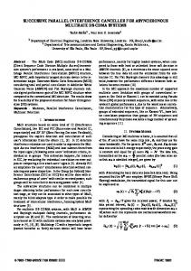
As the nal step, pairs of PR's (corresponding to the up and down transitions of a variable) are implemented as gates from a standard repertoire of gates. For example, the pair of only PRs in p2 stands for a C-element whose inputs are di and li and whose output is a fork with two branches lo and do . From the PRs of p1, ci 7! s " and the matching ri 7! s # represent an SR- ip op but it can be replaced by a C-element as shown in gure 3 since :ci _ :ri holds invariantly for p1. Two points to note: � A property of the program can be used to generate choices for components in a circuit. � This circuit requires the forks with inputs ri and ci to be isochronic. Because, for example, the down-transition ci # is acknowledged by the C-element in gure 3, but down-transition in the branch of ci driving the AND-gate is NOT acknowledged (See next subsection.) do
li
ci
ro s
C di
lo p2
co
s
C ri
p1
Figure 3: Gate-circuit for a QEC
Priyadarsan Patra
2.3.5 How is delay-insensitivity achieved
18
For a PRS to represent DI hardware, it must have the following two properties in order two avoid generation of indeterminate or unwanted values : Non-interference Consider any two PR's G1 7! S2 and G2 7! S1. If S1 is an up transition on a variable x and S2 a down transition then :(G1 ^ G2) is invariant. This condition rules out gates whose output might be subject to a \ ght" between logical zero and one. Stability Once a guard holds it can be falsi ed only in the states where the corresponding transition is true (i.e. where the transition is ine�ective.) The intention of this condition is to ensure that all the gates, driven by a variable, whose outputs might change as a result of a transition of this variable do receive the transition before it's undone by an opposite response-action. The stability property guarantees us that a variable won't transition until it receives \acknowledgements" (acks) from all the gates it is an input of. This suggests feedback loops that self-time the gates. In Martin's method, execution of a response-action of a PR serves as acknowledgement of the up OR down transitions of the variables in the guard of the PR that made this PR rable. Intuitively, execution of a response-action guarantees prior execution of all preceding response-actions and hence serves as a \witness" for them. It turns out the mechanism of acks to sequence actions in processorder also implements stability [Mar89b]. Since the transformations only enforce sequence and NOT time, they ensure delay-insensitivity. A theory of asynchronous circuits that assumes atomic transitions but allows arbitrary wire delays can do away with the atomicity assumption by insisting that the signals be monotonic. This makes the circuit model more realistic as transitions in VLSI are non-atomic and signals non-discrete. Given monotonic circuit outputs, a gate will not miss the transition because of its higher threshold nor see spurious transitions (possible with nonmonotonic signals) as long as the input stays stable su�ciently long. But note that monotonicity is required of a transition between two di�erent logical values. Such monotonicity is neither necessary nor possible (due to noise, e.g.) within well-de ned regions of the signal. Martin's theory disallows a PR (the result of) whose execution falsi es its guard. A gate obtained from such a PR will not have stable output.
Priyadarsan Patra
19
The theory also assumes availability of isochronic forks to build su�ciently complex circuits. Implementation of such a fork requires that delay di�erence in the branches of a fork is smaller than the delay in the gates being driven and that those gates have similar thresholds such that explicit acknowledgement of a transition in one branch is tantamount to acknowledgement of the same transition in the other.
2.3.6 Some remarks
The e�ciency of the circuits depends on the rst 3 steps. Martin [Mar86] gives a less e�cient (slower) but smaller design by reshu�ing the QEC program. It suggests that Martin's method can be more useful if we can capture all the properties we want in a system at the program level. So, a programming system/model that allows more powerful yet easier reasoning abilities at di�erent steps of transformation, is called for. It has been recognized (e.g. see [Mar90] and [BE90]) that the class of purely DI circuits is severely limited (to networks possible with only Celements, inverters and wires.) Martin [Mar86] introduced `isochronic forks' so that a transition need only be acknowledged by one gate receiving it. It's not clear how to systematically minimize use of such forks in systems where possible. Ebergen shows in [Ebe89] that a circuit made up of only DI components (de ned more rigorously in next section) is DI. The QEC circuit we obtained here has AND gates which are not DI | not all combinations of input transitions are acknowledged ([Mar90]).
2.4 \Synchronized Transitions"
Greenstreet & Staunstrup [SR89] describe a technique to represent a system with a program of \synchronized transitions" which are a stylized version of guarded commands (statements) which are concurrent-composed. This program is then analysed and re ned to the level such that it satis es what they call certain \local" and \global" restrictions. The local restriction is nothing but the monotonicity requirement on circuits and the global restriction is called \a pair of implementation conditions." Note that a whole statement like shown below is called a \synchronized transition" (ST).
Priyadarsan Patra
20
> The hats denote vectors (multiple assignment), C a guard, f^ a vector of functions. This ST is said to read all variables mentioned in C and r^ and write all variables in ^l. The program is analysed to see that the \consumed values" and \correspondence" implementation conditions are met. Concurrent program veri cation techniques (Owicki [OG76]) are used. Consumed Values: All \synchronized transitions" reading a particular variable are required to `notice' (consume) the value of the variable between any two consecutive writings to it. We think that this is equivalent to requiring that between any consecutive transitions on a variable, the rst transition be acknowledged by all gates the variable feeds to. Correspondence Condition: Once an ST is activated (that is C is true and the ST, if executed, will e�ect a state change) it can only be deactivated only by executing the ST. This condition is exactly like the `stability' requirement in Martin's terminology. It turns out that the two implementation conditions are too strong in the sense that any given ST performs the same sequence of actions for all valid program executions when started on a xed initial state. A similar result has been shown in Muller & Bartkey [mb559]. This is also to be expected in the light of the observation I made about isochronic forks. In spite of this drawback in theory, the technique has been used to verify a self-timed chip for division designed at Stanford.
2.5 Signal Transition Graphs
Chu [Chu87] has developed a methodology to specify circuits in the form of Signal Transition Graphs (STG) which are based on \live-safe free-choice" petri-nets. An STG represents signal transitions as �nodes and precedence constraints among transitions as directed edges. u ?! v denotes a path of any nite length from transition u to v. The \control" is de ned by the \markings" (tokens in certain places of the petri-net). Note that, both the
Priyadarsan Patra
21
system and the environment are modeled together as a single closed system. The input transitions are constrained to have in-degree equal to one (its rami cations not discussed here). The synthesis procedure sets out by rst checking liveness and persistency properties of the STG's syntax, if not satis ed the graph is augmented with extra edges. Then after some optimization on the graph (contraction, etc.) a state graph is generated which is compiled into an actual circuit in the traditional way of circuit design (\state assignment" must not introduce nonpersistency.) Liveness: An STG is de ned to be live if it's strongly connected thereby guaranteeing that each transition is followed by another well-de ned transition. Furthermore, each transition is required to alternate in each simple cycle of the graph whereby ensuring that two consecutive transitions on a node is not both Up or both Down. This property certi es some \well-formedness" of a circuit. � � Persistency: If s ?! s0 and s ?! t exist, then there must exist t ?! s0 where s and s0 are opposite transitions on the same (binary) variable. This condition corresponds to our de nition of stability (or correspondence condition) in previous two methods and hence, leads to \speedindependence" (or semi-modularity as in Molnar [MFR85]).
2.6 Dill's Veri cation Technique
Conventional techniques to debug and check combinational and sequential circuits are inadequate for asynchronous circuits because no clock exists for synchronization and all delay combinations cannot be tested. Dill [DC85] describes a technique to verify a circuit speci ed in Propositional Temporal Logic (CTL) by rst creating a state graph from the speci cation and then running the model checker against it for checking some temporal logic formulae for delay-insensitivity. The model checker allows for telling it that only certain paths (e.g. fair execution sequences wherein a process that is continuously enabled eventually res) be checked. The problem is the size of state graphs for the fsm's could blow up.
Priyadarsan Patra
22
Later, Dill [Dil89] presents an improved technique by introducing a notion of conformance which says that an implementation SI conforms to the system S i� SI accepts all the inputs that S accepts and generates an output only if generated by S . This new technique checks speed-independence of a set of communicating fsm's by \simulation" to prove two-way conformance between SI and S to certify that SI is a speed-independent realization of S . The simulation algorithm (similar to Ebergen's) is given below: 1. Start the fsm's in their respective \start" states. 2. If none of the fsm's is in a state to produce an endogenous action 7, then the simulation is over, stop after reporting \conformance".. 3. Or else, for every concurrently possible endogenous action of every fsm, do in parallel the following steps in order: � Perform the (endogenous) action. � For all fsm's whose input alphabet contains the action in previous step, check that each of them can accept the action as input. If not, then the set of fsm's have computation-interference and so report \non-conformance" and stop. � If the previous step is passed, advance the states of all fsms generating or accepting an action. � Go to step 2 if a new (never visited) global state is obtained otherwise stop reporting \conformance".
3 UNITY Formalism for DI design ? It seems to us that UNITY [CM88] programs are better suited for implementation as DI circuits than the sequential CSP-like programs used in Martin's method. Note that the process-decomposition step in Martin [Mar90] really did not add concurrency even though we get a concurrent composition of processes. 7
a spontaneous output event
23
Priyadarsan Patra
More over, the proof framework for UNITY is simple and powerful to reason about properties at di�erent stages of transformation, thereby enabling the designer to weigh di�erent options (for implementation) more formally. The weak fairness (implied by UNITY's unconditional fairness) matches well with the requirement that every gate that is continuously active be eventually allowed to re assuming we can guarantee Martin's stability requirement. We have seen DI circuits made out of monotonic hardware do not require atomicity of single assignments. A similar argument can be put forward to show that even multi-assignments need not be executed simultaneously (to observe this point, suppose that a system could perform multi-assignments \simultaneously." Now, because the environment of the system senses these values through wires of arbitrary delay, the simultaneity is of no additional constraint.) A source of di�culty is the implementation of mutual exclusion among statements (read concurrent processes) assumed by UNITY semantics and that might force the use of too many arbiters. A DI characterization in Chandy & Misra [CM88] (which is equivalent to Martin's stability criterion and those in Staunstrup & Greenstreet [SR89] implementation conditions) may be formulated as follows: For a program G to be DI, it must satisfy the safety property: h8y : \y := e if b" in G :: b ^ (e = E ) unless (y = e) ^ (e = E )i Note that, an assignment of the form \y := e if b" can be replaced by: y := true if e ^ b y := false if :e ^ b We attempt a DI realization of a QE process described in UNITY syntax below :
Declare
integer i; boolean F; boolean q[0::N ];
Initially hki : 0 < i � N :: q[i] = F i
Assign h i : 0 < i � N :: q[i ? 1]; q[i] := F; q[i ? 1] if q[i] = F ^ q[i ? 1] 6= F q [i ? 1] := q [i ? 1] b
a
24
Priyadarsan Patra
end
qc[i ? 1] := qd[i ? 1]i
Here, q[0] and q[N ] serve as the environment's Output and Input nodes, respectively. F is False or True depending on whether the queue is assumed empty or full initially. Since hardware is not atomic unlike UNITY assignments, we model nonatomicity with delays. But, since we are interested in DI designs (with monotonic hardware), we can view non-atomicity equivalently as some arbitrary communication delay between the time a writer process changes a state and the time a neighbor (reader) \observes" it. Since a QE process is capable of changing states of itself and its left neighbor, this is tantamount to two `wires' between two neighboring processes where delay in the two directions between q[i-1] and q[i] is modeled by the two UNITY assignment statements, (qc[i ? 1] := qd[i ? 1])and(qb[i ? 1] := qa[i ? 1]). The modi ed program's Assign section follows (initially, all variables set to F) and the process interconnection for element i ? 1 and i follow: h i : 0 < i � N :: qd[i?1]; qa[i] := F; qb[i?1] if qc[i] = F ^ qb[i?1] 6= F qb[i ? 1] := qa[i ? 1] qc[i ? 1] := qd[i ? 1]i q [i-1] a
q [i-1] b
element i-1
element i
q [i-1] c
q [i-1] d
Figure 4: Two adjacent queue elements The program in the present form is not DI. Among others, the wire \qb[i ? 1] := qa[i ? 1]" violates the DI safety property. To see this, suppose this wire is very slow and data from environment is coming in a fast rate. Then, data could be \dropped" by this wire. A modi cation of this program (which I don't present) follows a DI signalling protocol, but for the whole circuit to be DI, the QE's themselves need to be built of components obeying \input-output mode" of operation. This suggests that research be done for approaches to decompositions and construction of a library of elementary DI components. Need for isochronic forks exists as in other techniques.
Priyadarsan Patra
25
4 Concluding Remarks This paper describes some existing synthesis and veri cation techniques for asynchronous circuits. Still, notables like Charles Molnar's work [MFR85] and \process algebra" [JJH90] developed at Oxford are totally left out. The paper has tried to just about scratch the surface of potential techniques for practical circuit design using UNITY and a lot remains to be done. [GJ90] points out that there exist several tradeo�s between di�culty of circuit/layout design vs silicon area penalties vs claims of `delay-insensitivity by construction'. Actually, some of the components in DI repertoire of Ebergen, Udding, et al. are ine�cient in area and often can be implemented e�ciently with fundamental mode assumption. These tradeo�s need to be understood well. Seger [Seg87] has shown that no DI realization of a mod-k, k > 1 counter is possible even under fundamental-mode operation. Furthermore, it is shown that no DI implementation using solely logic gates exists for so basic a component as a C-element when the more practical input-output mode of operation is assumed [BE90]. The reason for unrealizability of a whole range of DI circuits is due to the very pessimistic assumption that arbitrary delays are possible. Papers such as [Seg87] advocate more reasonable (less pessimistic) assumptions of delay as in, for example, the bounded-delay model where nite lower and upper bounds on wire delays are assumed. Our intuition is that adopting a `multi-tiered' delay assumption is most useful, for instance, a bounded-delay model for design of a nite basis of DI components and an arbitrary-delay model at higher system levels (to justify response times in systems such as an asynchronous neural computing network or a distributed multi-processor.) More issues that come to mind are: � Can we guarantee the (implicitly assumed) monotonicity property of circuit voltages with the new and upcoming fabrication technologies like Gallium-Arsenide ? � How to capture in a theory dynamic implementations for asynchronous circuits (for reasons of time and space e�ciency) ? � How about \self-stabilizing" asynchronous circuits ?
Priyadarsan Patra
26
� How can we carry the lessons learnt in veri cation of asynchronous
circuits to arbitrary software systems ? � Is there a formal way of relating e�ciency of circuit implementation to its \run-time" e�ciency ? One also needs to develop techniques to build testable asynchronous circuits because in spite of correctness of the synthesis, fabrication \bugs" creep in and we do not have, e.g., the services of a clock to single-step to test the circuit.
References [BE90] [Chu87] [CM88] [DC85] [Dil89] [Ebe89] [GJ90] [Hoa78]
S. Brozozowski and J. C. Ebergen. On the delay sensitivity of gate networks. Tech Report CSN90/X, Eindhoven University of Technology, 1990. T. A. Chu. Synthesis of Self-timed VLSI Circuits from Graph Theoretic Speci cation. PhD thesis, Massachusetts Institute of Technology, September 1987. K. M. Chandy and J. Misra. Parallel Program Design. Addison-Wesley, 1988. D. E. Dill and E. M. Clarke. Automatic veri cation of asynchronous circuits using temporal logic. Computer Science Press, 1985. D. E. Dill. Trace Theory for Automatic Hierarchical Veri cation of Speed-independent Circuits. PhD thesis, CMU, 1989. An ACM Distinguished Dissertation. J. C. Ebergen. Translating programs into delay insensitive circuits. CWI Tract 56, 1989. G. Gopalakrishnan and P. Jain. Some recent asynchronous system design methodologies. Technical report, University of Utah, 1990. C. A. R. Hoare. Communicating sequential processes. Communication of the ACM, 21(8):666{667, 1978.
Priyadarsan Patra
27
[JJH90] H. Jifeng, M. B. Josephs, and C. A. R. Hoare. A theory of synchrony and asynchrony. Oxford University Programming Research Group, Israel Conference, 1990. [Mar86] A. J. Martin. Self-timed fo. Caltech Tech Report, 1986. [Mar89a] A. J. Martin. Formal program transformations for self-timed vlsi circuits. Formal Development of Programs and Proofs, E. W. Dijkstra, ed., Addison-Wesley, 1989. [Mar89b] A. J. Martin. Programming in vlsi. Caltech Tech Report, 1989. [Mar90] A. J. Martin. The limitations to delay-insensitivity in asynchronous circuits. Caltech Tech Report, 1990. [mb559] A Theory of Asynchronous Circuits. Harvard University Press, 1959. [MFR85] C. E. Molnar, T. P. Fang, and F. U. Rosenberger. Synthesis of delayinsensitive modules. Computer Science Press, 1985. [OG76] S. Owicki and D. Gries. An axiomatic proof technique for parallel programs. Acta Informatica, 6:1, 1976. [Seg87] C-J. Seger. On the existence of speed-independent circuits. Technical Report CS-87-63, Univ of Waterloo, Nov 1987. [Sei80] C. L. Seitz. System Timing, chapter 7, pages 218{262. Addison-Wesley, 1980. [Sne85] J. L. A. van de Snepscheut. Trace theory and vlsi design. In Lecture Notes in Computer Science 200. Springer Verlag, 1985. [SR89] J. Staunstrup and Greenstreet M. R. Designing delay insensitive circuits using synchronized transitions. 1989. [Sut89] I. E. Sutherland. Micropipelines. CACM, June 1989. [Udd86] J. T. Udding. A formal model for de ning and classifying delayinsensitive circuits and systems. Distributed Computing, 1:197{204, 1986.