MDA applied: From Sequence Diagrams to Web Service Choreography Bernhard Bauer1, Jörg P. Müller2 1 Programming of Distributed Systems, Institute of Computer Science, University of Augsburg, D-86135 Augsburg, Germany
[email protected] 2 Siemens AG Corporate Technology, Intelligent Autonomous Systems, Otto-Hahn-Ring 6, D-81739 München, Germany
[email protected]
Abstract. Web Services and Web Service composition languages for Web Service choreography are becoming more and more important in the area for inter-enterprise application and process integration. A huge amount of work has been done in the area of business process while web service composition languages have been the subject of intense research efforts recently. However the aspects of modeling these software systems have not been studied in detail, in contrast to the definition of business processes where well-known techniques exist. The model-driven architecture (MDA) approach of the Object Management Group is a good starting point for the development of Web Services and Web Service choreography. In this paper we show how platform independent models specified by UML 2 sequence diagrams can be automatically transformed in a Web Service composition language representation. We will start by introducing the notion of Web Services, Web Service compositions languages, and as well as MDA. After setting the global context of our work, we show theoretically and by a small case study how UML 2 sequence diagrams can be refined to Web service choreography.
1
Introduction
Over the past few years, enterprises are currently in a thorough transformation process as they encounter the necessity to react to challenges such as globalization, unstable varying demand, and mass customization. A most important factor to maintaining competitiveness is the ability of an enterprise to describe, standardize, and adapt the way it reacts to certain types of business events, and how it interacts as well as its procedures for interaction with suppliers, partners, competitors, and customers. Today, virtually all larger enterprises describe these procedures and interactions in terms of business processes, and invest huge efforts to describe and standardize these processes. Web Services are the key technology for Enterprise Application Integration (EAI) and Inter Enterprise Integration. IBM defines Web Services as [1]: “Web services are self-contained, self-describing, modular applications that can be published, located, and invoked across the Web.”
Web Services are seen as a promising technique to cope with this problem of accessing applications across the Internet in a standardized way, i.e. accessing software modules via XML interfaces. Thus Web Services (see e.g. [2]) allow e.g. the access of functionality over the Internet, to cope with a complete intra- and inter-corporate integration of heterogeneous systems (i.e. EAI; see e.g. [3] for details) based on XML, and supporting software re-usability. A further interesting aspect of viewing Web Services is that, after they are deployed as components or services in the Internet, it is possible to combine them to added-value Web Services offering more functionality than the original ones,. This process is called called Web Service Choreography or - composition depending on the point of view of the description. Thus Web Service choreography deals to some extent with business processes. Looking at Web Services in the context of business integration, i.e. inter-enterprise integration (B2B integration), the Web Service standards can be applied to automate the processes between different enterprises, by allowing a company e.g., to access directly services offered by a supplier. However the interoperation of the different Web Services has to be modeled and defined. For this purpose a variety of Business Process languages for Web Services are under development including, BPEL4WS [4], BPML [10], XPDL [7] and the process description facilities of ebXML [9], called ebXML Business Process Specification Schema [8]. In this paper we focus on BPEL4WS which currently seems to be the business process language in the Web Service area.with the highest momentum The trend towards process-centered modeling and operation of enterprises brings new opportunities for software technologies that support the monitoring, management, and optimization of processes. To live up to its potential, it requires software technologies to relate to business processes as well as service choreography, to understand them and to hook into them where required. Based on OMG’s model-driven approach, our objective is to demonstrate a mapping of platform independent models based on UML 2 sequence diagrams [13] (triggered by e.g. [16]) to a platform dependent model based on the Business Process Execution Language for Web Services (BPEL4WS). This paper can be seen as part of a series of papers dealing with software engineering starting from business processes and transforming them into web services choreography, see e.g.[20, 19]. The structure of the paper is as follows: In Section 2, we set the technological background and provide the conceptual architecture of our work. Section 3 contains the main technical part of the paper dealing with the automated transformation of the UML 2 sequence diagrams to BPEL4WS. We conclude in Section 4 with some discussion of future research opportunities.
2
Setting the Context
In this section, we set the context of our work, starting with a brief overview on MDA and Web Services. After this we describe the overall methodology defining the relationship between web services, business processes, and MDA.
2.1
Model-driven architecture
The Model Driven Architecture (MDA) (for details see [11, 12]; this section is based on [12]) is a framework for software development driven by the Object Management Group (OMG). Key to MDA is the importance of models in the software development process. Within MDA the software development process is driven by the activity of modeling the software system. The MDA development process does not look very different from a traditional lifecycle, containing the same phases (requirements, analysis, low-level design, coding, testing, and deployment). One of the major differences lies in the nature of the artifacts that are created during the development process. The artifacts are formal models, i.e. models that can be understood by computers. The following four models are at the core of the MDA: • Computational Independent Model (CIM): This model describes the business logic and therefore defines business processes and workflows in detail. This model has to be annoted to transform it into a platform independent model. • Platform Independent Model (PIM): This model is defined at a high level of abstraction; it is independent of any implementation technology. It describes a software system that supports some business. Within a PIM, the system is modeled from the viewpoint of how it best supports the business. Whether a system will be implemented on a mainframe with a relational database, on an agent platform or on an EJB application server plays no role in a PIM. • Platform Specific Model (PSM): In the next step, the PIM is transformed into one or more PSMs. It is tailored to specify a system in terms of the implementation constructs available in one specific implementation technology, e.g. Web Services. A PIM is transformed into one or more PSMs. For each specific technology platform a separate PSM is generated. Most of the systems today span several technologies; therefore it is common to have many PSMs with one PIM. • Code: The final step in the development is the transformation of each PSM to code. Because a PSM fits its technology rather closely, this transformation is relatively straightforward. 2.2
Web Services
Describing software architecture in a service-oriented fashion, while being increasingly popular, is not a new idea; it is what CORBA has been about more than a decade ago. Recently, the concept of web services has given new momentum to serviceoriented architecture. Web services are self-contained, self-describing, modular applications that can be published, located, and invoked across the Web using existing web protocols and infrastructure. The core web service standards are the Web Service Definition Language (WSDL), Simple Object Access Protocol (SOAP), and Universal Description, Discovery and Integration (UDDI). The combination of relative sim-
plicity, platform independence, and leveraging of HTTP positions web services to become an important architecture for wide-scale distributed computing [17]. 2.2.1
Web service definition
WSDL is an XML based specification for describing what a program module does (interface description), what the result of the module’s activity is, and how to communicate with it. A WSDL document resides at a URL location, e.g. at a UDDI, and is linked to the module, which itself may reside at any location. Web Services exchange information through SOAP messages. SOAP is a protocol for Remote Procedure Call / Remote Method Invocation over HTTP. SOAP uses XML to define the message format and how variables and parameters required by the program are sent to it to invoke its methods. The program in turn, sends the results of its process back to the request originator in another SOAP message. Because HTTP is one of the transport mechanisms used by SOAP, a Web Service method call can be made to and from any Web enabled computer anywhere in the world. 2.2.2
Web Service Choreography
According to [18], web service choreography describes the specification of the interaction (i.e., ordering of messages) among a collection of services from the perspective of one service or a collection thereof. Web service choreography allows applications to combine existing web services in order to obtain more elaborated value-added web services. Note that choreography deals with the definition of these interactions, not with their execution. At the moment, several standards are under development for the definition of languages for Web Service composition or Web Service Choreography. E.g. IBM and Microsoft have combined their respective Web Service centered process languages (Web Services Flow Language (WSFL) and XLANG)) into the Business Process Execution Language for Web Services (BPEL4WS [4]). The Business Process Management Initiative (BPMI [6]) has published BPML [10]. The Workflow Management Coalition (WfMC) proposed another standard called XPDL [14]. ebXML1 [9] has the goal to provide an open XML based infrastructure enabling the use of electronic business information in an interoperable, secure and consistent manner, in particular from a workflow and business process perspective. The ebXML Business Process Specification Schema [8] provides a standard framework by which business systems may be configured to support execution of business collaborations consisting of business transactions. Exemplarily we will have a closer look at BPEL4WS. It can be observed that most Web Service composition languages are fairly similar as far as the constructs for defining processes are concerned. The main difference among them is grounded in how modeling the context of protocols is represented and how they deal with transac-
1
ebXML was originally not developed with the focus on Web Services and Web Service Composition, but is more or less based on the same motivating ideas.
tions. These aspects, however, are beyond the scope of this paper. In this paper, we shall consider BPEL4WS in more detail.
Semantic Business Process Specification
UML 2 Activity Diagrams
CIM
Semantic Activity/Service Interface Definition
Semantic Service Choreography Definition
UML 2 Sequence Diagrams
PIM transformed
PSM FIPA Service Ontology
transformed Web Service Interface Definition (WSDL)
Static model (service model)
FIPA interaction protocols
BPML
Web Service Process Choreography (BPEL4WS)
Dynamic model (service choreography model)
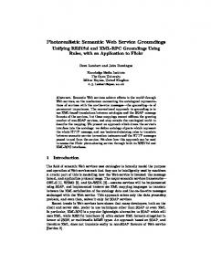
Figure 1. Overview of model-driven development methodology for Web Service enabled business processes
2.3
Conceptual Methodology
Figure 1 (an updated version of Figure 3 of our position paper presented in [19]) illustrates the top-down development process starting with a semantic business process specification using and extending UML 2.0 activity diagrams. This specification is refined into two models: •
a static model, which is essentially the service model in our conceptual methodology, even though enhanced with metadata, such as the description of pre- and post-conditions for service invocation, and with exception definitions;
•
a dynamic model, which is essentially the service choreography oriented layer in the conceptual methodology.
Each of these two models is described by a platform independent model and one or more platform specific models. For the computational independent model we propose
to use Activity Diagrams as provided by UML 2.0 to model business processes, since an activity diagrams depicts behavior using control and data-flow model. In particular, it describes activities and flows in different details. We propose the usage of UML 2.0 for the platform independent model both for service definition and service choreography definition, namely sequence diagrams for the latter one, describing an interaction by focusing on the sequence of messages that are exchanged between business partners, along with their corresponding event occurrences on their lifelines. In addition, we had provided exemplary mappings to Platform Specific Models, using WSDL to specify the services/activities and using BPEL4WS for the service choreography. In this paper we will focus on the mapping of UML 2 Sequence Diagrams to BPEL4WS as a part of the development process. Readers interested in the other parts are referred to [19, 20].
3
From Sequence Diagrams to BPEL4WS
This section is structured as follows. First we introduce UML 2 sequence diagrams by a small application example. Then give a short overview on BPEL4WS before we define an informal inductive mapping from the constructs of sequence diagrams to BPEL4WS 3.1
Application example
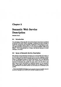
To illustrate our approach, we introduce an application example taken from the FIPA interaction specifications, namely the FIPA Iterated Contract Net protocol [15]. Here we define a complex negotiation between two parties which can also be seen as a pattern of interaction which could be instantiated for specific purposes, similar to predefined sub-processes e.g. for automated SCM. The Customer (Initiator) first orders an item via the message cfp(call for proposals). The Order Acquisition agent (Participant) has two choices: either (1) accepts the order because the price and delay match the production planning and the cost (via the message propose) or (2) refuses the order and proposes to negotiate (via the message refuse). The Customer can then refuse the proposal from the Order Acquisition agent and ends the interaction (via the message reject-proposal) or makes a counter-proposal. This negotiation continues as long as the Customer decides to negotiate the requirements. Then, she can finish the interaction (depicted by the alternative Final iteration) and two choices are offered to her: either rejects the proposal via the message reject-proposal or accepts the proposal via the message accept-proposal. In this latter case, the Order Acquisition agent fills the order and informs the Customer that her order is delivered. In case of failure in the production, the Order Acquisition informs the Customer via the message failure. In Figure 2 we define the main elements of the UML2 sequence diagrams by this example. In the following we will have a closer look at BPEL4WS.
interaction Lifeline
time constraint
Continuation ("goto")
alternative
constraint message end of message flow
Figure 2: FIPA Iterated Contract Net Protocol
3.2
BPEL4WS
The business processes use the following components of BPEL4WS (following [4]): • Service Linking, Partners and Service References: The relationship of a business process with a partner is typically peer-to-peer, requiring a two-way dependency at the service level. The notion of service links is used to directly model peer-topeer partner relationships. Service links define the relationship with a partner by the message and port types used in the interactions in both directions. However, the actual partner service may be dynamically determined within the process. • Messages properties: The data in a message consists conceptually of two parts: application data and protocol-relevant data, where the protocols can be business protocols or infrastructure protocols providing higher quality of service, like security and transaction. The business protocol data is usually found embedded in the application-visible message parts, whereas the infrastructure protocols almost always add implicit extra parts to the message types to represent protocol headers that are separate from application data. Business processes might need to gain access to and manipulate both kinds of protocol-relevant data. The notion of message properties is defined as a general way of naming and representing distinguished data elements within a message, whether in application-visible data or in message context. Message properties are defined in a sufficiently general way to cover message context consisting of implicit parts, but the use focuses on properties embedded in application-visible data that is used in the definition of business protocols and abstract business processes. A property definition creates a globally unique name and associates it with an XML Schema type. The intent is to create a name that has greater significance than the type itself. • Data handling: Business processes model stateful interactions. The state involved consists of messages received and sent as well as other relevant data such as timeout values. The maintenance of the state of a business process requires the use of state variables, which are called containers. Furthermore, the data from the state needs to be extracted and combined in interesting ways to control the behavior of the process, which requires data expressions. Finally, state update requires the notion of assignment. BPEL4WS provides these features for XML data types and WSDL message types. In BPEL4WS, Data handling is performed by using the following features: • Expressions: BPEL4WS uses several types of expressions: Boolean-valued expressions used for transition conditions, join conditions, while conditions, and switch cases; deadline-valued expressions used with the "until" attribute of onAlarm and wait; duration-valued expressions used for "for" attribute of onAlarm and wait; general expressions based on XPath 1.0 used in assignments. Moreover, BPEL4WS provides an extensible mechanism for the language used in these expressions. The language is specified by the expressionLanguage attribute of the process element.
• Containers: Containers provide the means for holding messages that constitute the state of a business process. Containers can hold messages, either received or temporary defined, that act as "temporary variables" for computation and are never exchanged with partners. Containers can be specified as input or output containers for invoke, receive, and reply activities. At the beginning of a process all containers are not initialized. Containers can be initialized by a variety of means including assignment and receiving a message. Containers can be partially initialized with property assignment or when some but not all parts in the message type of the container are assigned values. • Assignments: Copying data from one container to another is a common task within a business process. The assign activity can be used to copy data from one container to another, as well as to construct and insert new data using expressions. • Activities: BPEL4WS distinguishes between two types of activities: basic and structured activities. • basic activities: The receive construct allows the business process to do a blocking wait for a matching message to arrive. The reply construct allows the business process to send a message in reply to a message that was received through a receive. The combination of a receive and a reply forms a request-response operation on the WSDL portType for the process. The invoke construct allows the business process to invoke a one-way or requestresponse operation on a portType offered by a partner. The assign construct can be used to update the values of containers with new data. An assign construct can contain any number of elementary assignments. The throw construct generates a fault from inside the business process. The terminate construct allows to immediately terminate a business process. The wait construct allows to wait for a given time period or until a certain time has passed. Exactly one of the expiration criteria must be specified. The empty construct enables insertion of "no-op" instructions into business processes. This is useful for synchronization of parallel activities, for instance. • structured activities: The sequence construct allows one to define a collection of activities to be performed sequentially. The switch construct allows selecting exactly one branch of execution from a set of choices. The while construct allows one to indicate that an activity is to be repeated until a certain success criteria has been met. The pick construct allows blocking and waiting for exactly a suitable message to arrive or for a time-out alarm to go off. When one of these triggers occurs, the associated activity is executed and the pick completes. The flow construct allows specifying one or more activities to be executed in parallel. Links can be used within parallel activities to define arbitrary control structures. The scope construct allows defining a nested activity with its own associated fault and compensation handlers. The compensate construct is used to invoke compensation on an inner scope that has already completed its execution normally. This construct can be invoked only from within a fault handler or another compensation handler.
In the remainder of this section, we describe the transformation of UML 2 Sequence Diagrams to the Web service choreography language BPEL4WS. 3.3
Mapping
As a next step we will now go into the details of UML 2 sequence diagrams and define informally2 by induction the mapping of sequence diagram elements to BPEL2WS, i.e. a mapping transform: Sequence Diagram Element → BPEL4WS
A sequence diagram defines an interaction denoted as . Thus a complete sequence diagram is transformed into a process definition of BPEL4WS: transform (
) =
transform(inner_part(
))
where inner_part delivers the sub-diagram defined in the overall sequence diagram. Lifelines are a modeling element that represents an individual participant in an interaction. A lifeline represents only one interacting entity. They are transformed by the following rule: transform (
…) =