285. FUNCTIONAL VERIFICATION IN AN INTERACTIVE SYMBOLIC. IC DESIGN ENVIRONMENT. Bryan Ackland. Neil Weste. Bell Laboratories. Holmdel, New ...
285
FUNCTIONAL VERIFICATION IN AN INTERACTIVE SYMBOLIC IC DESIGN ENVIRONMENT Bryan Ackland Neil Weste Bell Laboratories Holmdel, New Jersey 07733
ABSTRACT
This paper describes verification techniques that have been implemented as part of an interactive symbolic IC des ign system. Circuit analysis programs perform node extraction and gate decomposition. They generate both transistor and gate level circuit desriptions which are used as input to a transistor level digital MOS timing s imulator. The extraction programs make use of an intermediate circuit description language which captures both geometric placement and circuit connectivity. All programs are written in the C programming language and run under the UNIX operating system. An example is included to demonstrate the operation of these various techniques. l. INTRODUCTION
Functional verification is an important and necessary step in the design of large scale integrated circuits. It is that part of the design cycle which eliminates most, preferably all, of the human errors introduced in the forward part of the design. It is generally a two stage process consisting firstly of automatic circuit extraction, in which electrical circuit descriptions are generated from the physical layout, and secondly of functional simulation of the derived circuit. Symbolic design techniques simplify the circuit extraction task as they introduce structural or circuit information into the layout file and remove unnecessary geometrical data. Interactive design techniques, however, place additional constraints on verification in that they demand fast response in order to avoid slowing the interactive design cycle. This paper describes verification techniques that have been implemented on MULGA [ L] a UNIXt based interactive symbolic layout system. They consist of two programs which perform nodal circuit extraction and gate decomposition , and EMU - a transistor level MOS timing simulator. All programs are written in the C programming Language and run under the UNIX operating system in a microcomputer based design station. 2. MULGA
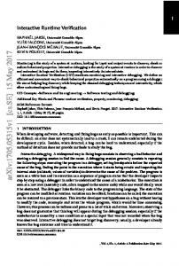
Symbolic layout provides a means of abstracting the detailed and often laborious task of mask design. rt offers the advantages of manual layout with regard to density, along with reduced design time and reduced likelihood of manual error . MULGA is a UNIX based interactive symbolic design system consisting of a suite of programs residing on a high performance color display station. Figure l shows the various software components of MULGA and
t
UNIX is a trademark of Bell Laboratories
CALTECH CONFERENCE ON VLSI,
Janua~y
1981
286
8 Pya n Acklan d
I
INTERACTIVE EOI TOR
PROCEDL OEFN .
NeiL Weste
-,
r---r - - - - - - I
~nd
' EMU GATE
MULGA
XY CONV.
CHIP ASSEMB.
INTERACTIVE EDITOR
Figure 1. MULGA design system the way in which they come together to effect a design. The system is based around
a symbolic Intermediate Circuit Description Language
(ICDL) which uses a derivation of the co-ordinode notation introduced by Buchanan and
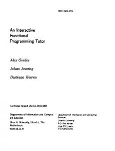
Gray (2]. It combines circuit topology with geometric placement on a coarse virtual grid. In this way , the language captures designer intent with respect to the circuit, rather than a collection of abstract geometric forms . The basic structure in ICDL is a cell which is a collection of elements placed on a virtual grid as show n in Figure 2. These elements may be devices, wires, contacts, pins, or other cell instances . Pins are named interconnection points that have no physical meaning in the final layout. They are a very important attribute of the language , however, and are used extensively in cell placement procedures and circuit verification. Figure 2 shows a CMOS 2-input nand gate represented graphically along side the textual JCDL description of the cell. Note that each line of text corresponds to an actual circuit component rather than a geometrical shape. Components are resticted to lie on grid intersection points as shown. Note, however, that this grid is only a relative placement network which defines the topology of the layout. Actual physical dimensions are determined later by a compaction process. ICDL cell descriptions may be generated either via the interactive editor or else procedurally using the C programming language. Once the designer is satisfied with the symbolic
COMPUTER-AIDED DESIGN S ES S I ON
287 Fun e 1 i o rz a ~
IC Des ' grz
10
6
4
2
V e r>
if i
c a t i on
1' >'!
•4 n
I
"1.
t P r> a. r• t i. v a SUm b o 1, i. c
g >'l Vi ~ nn m ent
begin nond2 pin ol 1 1 VII p i n ol 1 8 vdd pin poly 4 9 A pin poly 6 9 8 pin ol 7 ~ z dev n or•1 4 3 dev n or•1 6 3 dev p or • 1 4 6 dev p or • 1 6 6 wire ol 1 1 8 wire ol 1 8 8 wl r e poly 4 3 wl r e poly 6 3 wire o I 3 6 7 wl r e Ndlf 3 1 wire Pdif ~ 6 con cut 7 3 con cut 7 6 con cut 3 1 con cut 3 6 con cut ~ 8 end
1
8 4 9 6 9 6 7 3
3 3 ~
8
Figure 2. ICDL description of 2-input CMOS nand gate
description , the file is compacted. The compaction program examines each symbolic grid line in the layout to determine how far it must be spaced from its neighbours in order to satisfy process design rules. Compaction information is stored in th e design grid file. This file, along with the original IC DL description defines the minimum cell geometry assuming no o ther constraints in the design . A chip assembler program takes the design grid file along with a specified c hip floor plan and generates a mask coo rdinate file describing the actua l physical location of the symbolic grid lin es in the final layo ut. The chip assembler frequently needs to expand previously compacted cells in order to maintain global co nnectivity. The final step in the forward d esign path is the conversio n a nd placem e nt of cells into XYMASK data files. XYMASK is the geometric mask definition langu age used by the Bell System. A seco nd interactive editor provides a means whereby the designer can view a nd evalua te his final design . The verification phase consists o f two circuit extraction programs a nd EMU - a transistor level MOS timing sim ulator. The first program performs node extraction a nd produces , in addition to the node list, a transistor level description of the circuit s uitable as input to a circuit simulator such as SPICE. The second performs gate decompositio n producing the higher level circuit description required by EMU . The following sections describe the operatio n of these three programs .
CALTECH CONFERENCE ON VLSI,
Januar>y 1981
288
3. NODE EXTRACTION
The complexity of the circuit extraction process is heavily influenced by the nature of the layout definition language. One of the advantages of ICDL is that it carries implicit circuit connectivity information along with the physical topology . As shown in Figure 3, devices have designated connection points which are related by simple geometric rules to the center of the device. Wires serve to connect devices and external connections via interlayer contacts. Electrical connectivity is established when two elements exist on the same layer at the same virtual grid position. The pin construct aids the designer in naming specific nodes and connection points. This implicit connectivity is used, in conjunction with a simple algorithm, to arrive at a transistor node table description of the cell.
Figure 3. Implicit connectivity of ICDL components The algorithm begins by first reading in a complete description of the JCDL cell. Following this, each pin, contact and transistor connection is assigned a different node number. Figure 4 shows a hypothetical net of components labelled in this manner. If there were no wires in the circuit, all such initial node numbers would be unique. Wires serve to connect components and reduce the overall number of unique nodes in the circuit. Accordingly, each wire is examined in turn to determine which nodes are redundant. A list is made of all nodes belonging to that wire. If the wire crosses another wire of the same type, connectivity is established by adding one node from the new wire to the old wire node list. These wire node lists are used to eliminate redundant node numbers and generate a node net list description of the circuit. Pin names are used, wherever possible, to identify named nodes. Un-named nodes are given an internally generated name. Parasitic capacitance values for each node are calculated using the topology contained in the JCDL description along with absolute grid dimensions obtained from the mask coordinate file and specified process parameters. At this stage, sufficient information has been gathered to produce a transistor level circuit description. A simple filter converts this data into a SPICE simulation file. Figure 5 shows the simulation file generated from the 2-input nand gate described in Figure 2.
COMPUTER-AIDED DESIGN SESSION
Functionar VePification in an IC Desig n Envi ~ onment
Inte~a~tCve
~y m boli~
19
18
10
X
3
12
X
I
1 2
CONTACT
11
20
-8-DEVICE )i(
21
7
22
X 8 9 13
4 X 5
17
16
)i(
14 X 15
16
23
Figure 4. An example of initial node numbering
. SUBCKT nand2 ( vss vdd A B N7A MNl Ir21 A VSS vss N7A MN2 z B Ir21 vss vdd MPl z A vdd P7A vdd MP2 z B vdd P7A CMvss vss r2l CMTOSH 42 CNTvss vss r2l CN+H 12 CMvdd vdd r2l CMTOSH 42 CPTvdd vdd r2l CP+H 12 CPA A r2l CPTOSH 36 CPB B r2l CPTOSH 36 CMZ Z r2l CMTOSH 42 . FINIS
z
)
Figure 5. SPICE description of 2-input nand gate 4. SIMULATION
Analog circuit simulators s uch as SPICE give very accurate reliable feedback as to the functional operation of a circuit. They tend , how ever , to be very expensive in terms of computer and engineer time. ln a n interactive design environment, ease of operation a nd fast turnaround are of paramount importance and some accuracy can ofte n be sacrificed to achieve this . For these reasons, a UNIX based MOS timing simulator known as EMU was developed. An important feature of the simulator is the fact that it is a reside nt part of the design station software and is therefore capable of giving the designer fast feedback concerning the operation of his circuit.
CALT EC H CONFERENCE ON VLSI,
Janua~y
1981
290
I
I
III Ill 111,----,-1I I I
r---,I
1
I
I
L
I
I I
-
I
'
rI
I I
I I
I
I
--~ I I
I I I I I
CURRENT SOURCE
lvosl 2
lvs =f3 [;] [(VGs-V,) Vvs -
Saturation :
I v GS
-
v, I .:S I v DS I
los
where
w
(V~s> ]
rWI ]
= (3 [
(
VGS 2- V, ) 2
and I are the channel width and length respectively.
Back-gate bias effects are taken into account using table lookup techniques to calculate perturbations in threshold voltage. 4.4 OPERATION
The operation of EMU is characterized by four software states. Initially, EMU enters the command state. This is the common state from which all others can be entered. It is used to set simulation parameters, define clocks, display portions of the data base, initialize inputs and format the output of results. The circuit state is u sed to create a circuit description in the data
CALTECH CONFERENCE ON V£SI ,
Janua~y
1981
294
8Pyan Ackland a nd Neil Weste
base. It is used to define inputs and nodes, assign gates and set circuit capacitances. The process state is used to set process parameters such as transistor threshold voltage and transistor gain. The execute state represents the actual simulation. Following execution, the simulator return s to the command state. Command, input and process states each have their own input lang uage which may be entered interactively or via an predefined input file. 4.5 Performance EMU is written in C and will run on any UNIX based machine. ln particular, it runs o n the LS/ - 11 /23 - the host processor in the MULGA design station . It has also been implemented, however, on a VAX- 11 /780 and a Motorola 68000. The 11/23 implementatio n occu-
pies approximately 25K bytes of code space leaving 30K available for circuit deftnitio ns. This is s ufficient to hold a circuit of about 2000 transistors. Table I shows some simulation run times for a sample circuit - a 32Xl bit CMOS static RAM . This circuit contains 260 gates which in turn contain some 770 transistors. Note that eve n on the 11 /2 3 microcomputer, this type of circuit can be simulated in a time which compares favorably with the time needed to perform an off-line sim ulation on a larger machine.
SIMULATION RUN TIMES (sees)
LSI-11 I 23
1094
VAX-11/780
129
68000 {4 mHz)
1010
68000 (8 mHz)
585
TABLE I
SAMPLE RUN TIMES
5. GATE DECOMPOSITION
The nodal analysis program described in Section 3 produces a transistor net list which can be used to generate a transistor level circuit description for EMU. The speed of the si mulator, however, is directly related to the number of active current sources in the circuit. Accordingly, a gate extraction program has been written to process this transistor net list and convert it, where possible, into the compound gate structures recognized by EMU.
COMPUTER - AIDED DESIGN SESSION
295 Fun~"tion
tl
DeR : gn
Ver>ifi ~ rtf-inn
i"'. ''n
:-ntR~'1 !!'l '1 A c
1