Design of Fuzzy Logic Controller based on TMS320C6713 DSP Pallab Maji1 , Sarat Kumar Patra2 and Kamala Kanta Mahapatra3 Dept. of Electronics and Communication Engineering National Institute of Technology Rourkela, Odisha, India - 769008 Email: 1
[email protected], 2
[email protected], 3
[email protected]
Abstract—A Fuzzy Logic Controller (FLC) is designed with heuristic knowledge of the plant. There are several application based Fuzzy Logic Controllers in literature. However, application specific controllers lack reusability and are expensive, if not produced in bulk. This paper presents a general purpose and easily configurable fuzzy logic based controller which can work with 4 inputs and generates a control action based on the knowledge base. Expert operator knowledge can also be directly programmed into the knowledge base (also known as rule base) of the designed controller without ceasing the control operation. The ease of file handling and user interactivity of DSP processors is heavily exploited and TMS320C6713 DSP was chosen as the hardware platform. Further this paper also analyses the system performance with reference to the Fuzzy Logic Toolbox of Matlab. Index Terms—C6713 DSK, Code Composer Studio, Matlab, Run-time Reconfigurability .
I. I NTRODUCTION Fuzzy logic based controllers in literature are mostly application specific [1-3] although some designs exhibits general purpose FLCs but mostly developed on FPGA [4,7,8]. The objective of this paper is to present a generalized FLCs developed in TMS320C6713 DSP which can be used in various applications by simply calibrating the Setting Parameter, which is explained in section V-A, and can be reprogrammed such that the system execution stays uninterrupted. Designing such a system in FPGA is very complex based on the issues with reconfigurability on run-time and developing a synthesizable code for such complex algorithms is arduous. The same process becomes easier to implement on a DSP processor because of its strength in file handling and its enormous flexibility in programming. Hence designing of FLCs in DSP reduced programming effort by large as well as allowing features of tunability and reconfigurability on the go. The FLC discussed in this paper is a configurable 4-input 1-output system which is achieved by multiplexing the inputs. A traditional PID controller can also be approximated using the same controller and a test case analysis of the same is limned in detail in section VI. The DSP is programmed through code composer studio (CCS), a cross compiler developed on open source IDE named Eclipse, in C language. A. Fuzzy Logic Controller The design of Fuzzy Logic Controller (FLC) does not relate to the mathematical model of the system and these controllers
are designed for non-linear plants having a complex transfer functions [5]. FLCs are governed by a set of ”if-then” rules, known as Knowledge Base or Rule Base, which drives the inference engine to produce output in response to one or a set of inputs. The inputs are in general real world analog signals and termed as Crisp input. These inputs are converted to fuzzy variables in Fuzzifier. This step however may include an ADC if the development platform is digital. The fuzzified inputs are sent to the inference engine to generate a controller response in fuzzy environment with the help of Knowledge Base. The inference engine operates with various fuzzy based operators viz. min-max, product-max etc. These responses are then defuzzified to real world analog signals in Defuzzifier [6]. Hence, the designing of FLCs deals with: • Deciding membership functions for Fuzzifier and Defuzzifier, • Deciding the input and output ranges based on heuristic knowledge, • Creation of knowledge base established on expert operator strategies, • Deciding the inference operators.
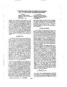
Fig. 1.
A Basic Fuzzy Logic Controller
As in Fig. 1 we can find FLC maps a crisp input to crisp output through four blocks. The Fuzzifier changes the crisp input based on the membership functions into fuzzy values or fuzzy sets. These fuzzy values are mapped in the inference engine to another fuzzy set which is derived from the knowledge base. Knowledge base consists of rules provided by expert or even obtained from numerical data. These rules are expressed as set of ”if-then” explicitly defining the nature of control action to be achieved for a certain input or set of
inputs. These rules decide the quality of the control action. Inference engine assigns a weight to the rules based on the inputs, implication and aggregation operators. This caters to the quantitative nature of the control action. FLCs can be implemented in analog as well as digital. However, digital fuzzy implementation is preferred for designing control circuits. This is because the analog implementation suffers curtailed programmability and reliable memory module. The simple way to realize digital FLC for design solutions in real-time is DSP processor. This approach allows accommodating high density programmable and complex logic in a single IC. Since the deployment of logic is through C language, this approach can be used for designs closely constrained with respect to time-to-market schedule. The nomenclature of dedicated digital FLCs is [9] • No. of Inputs and Outputs • Number and shapes of membership functions • Operators and size of premises for inference engine • Rule Base formulation • Defuzzification method In order to design a general purpose FLC, the above attributes of the controller has to be made programmable on user front. Various DSP based user friendly interfaces are available in the literature. GUI is the most preferred user interface. However, in this paper we discuss command line user interface through the console window provided by Code Composer Studio. B. TMS320C6713 DSK TMS320C6713 DSK, also referred to as C6713 DSK, is a DSP starter kit powered by a 225 MHz TMS320C6713 floating point DSP. It has a 512 KB FLASH memory and 16 MB SDRAM. The input and output channels are connected to a AIC23 stereo CODEC which has a sampling rate of 8-96 KHz. The range of the inputs to the system should be less than 40 KHz. For industrial application this is a formidable frequency range. The processor is capable of performing 1350 million floating point instructions per second (MFLOPS) [10]. This board is used in the proposed system development. The board is programmed in C language using CCS. The present version of CCS is version 5.2.x and is accompanied with a free license. CCS accepts C/C++ or assembly language source files. The C/C++ code is transformed to an assembly language source code file during compilation stage. The assembly language source file is translated to machine language object files and is based on the common object file format (COFF). The linker accepts COFFs and object libraries as input to produce an executable module. This module is dumped on the DSP. C. AIC23 Codec for Input and Output Interface [12] C6713 DSK uses TLV320AIC23, commonly known as AIC23 Codec, for analog input and output. AIC23 has a 16-bit ADC and a DAC which is based on sigma-delta technology. There are two analog input channels namely, MIC-In and LineIn. Both these channels are multiplexed and are digitized by a single ADC. However the two output channels, Line-Out
and Headphone (HP), are connected to the same DAC with gain of 12 to -34 dB and 6 to -73 dB respectively. Hence the system developed can have at most 2 inputs and 1 output. In order to accommodate more inputs, the innput channel were multiplexed. However peripheral expansion ports of C6713 DSK can be used to integrate more no. of I/Os. There is a 12 MHz crystal oscillator rendering clock to the DSP as well as the codec. For this codec, the possible oversampling rates are 250 Fs and 272 Fs. Hence the codec can sample analog input data at rates 8, 16, 24, 32, 44.1, 48 and 96 KHz. The system designed uses 96 KHz sampling frequency; highest sampling frequency possible for this particular board. Hereby the system is capable to process inputs with frequency less than 48 KHz. II. D ESIGN S PECIFICATION This paper depicts design and implementation a real-time standalone tunable DSP based FLC with following attributes • No. of Inputs(I): 4 (Configurable) • Input signal range: -5 to +5 Volts • No of Output: 1 • Output signal range: -5 to +5 Volts • Shape of Membership Function: Triangular • Number of MF for each input and output(Nmf ): 7 (Maximum and Configurable) Designing such a system in any hardware becomes challenging because of the interactive user interfaces and high complexity. To meet the requirements of the system and to implement it on a C6713 DSP, there were two blockades to be resolved, namely 1) Inference Rule Reduction, and 2) Reconfiguring the system without interrupting its execution. Maximum no. of rules to be managed by any system (Nr ) is as follows: Nr =
I Y
Nmf (k)
(1)
k=0
Thus based on eq. 1 the proposed system specifications suggests a rule base of 74 = 2401. This becoming the first blockade and the later actually deals with challenges in tunability and reconfigurability of the designed system in runtime with respect to the hardware chosen. III. I NFERENCE RULE R EDUCTION Due to limited memory and high complexity of rule evaluation, rule base reduction is necessary. An algorithmic approach was taken to reduce the no. of rule evaluation by eliminating all the rules that fired zero output [14] and only rules firing non-zero values in the fuzzy sets are used in the inference process. Thus when these zero values are discarded from the fuzzy sets, the inference engine is relieved of unnecessary calculations hence speeding up the inference time. In fig. 2, there are 3 membership functions namely M1, M2, M3. So the output fuzzy set for each input will be a set of
Algorithm 1 Rule Base Reduction Read No. of Inputs and Fuzzy values for each input. Determine non-zero inputs in each Fuzzy Set[nzFuzzy]. procedure F INDING N ON -Z ERO VARIABLES IN F UZZY S ET(F ) for i = 1 to no of inputs do for j = 1 to no of membership functions do if Fuzzy Value 6= 0 then nzFuzzy [i] [j] = j; . j ⇒ index of F else CONTINUE end if end for end for end procedure Calculate no. of non-zero rules fired N, for i = 1tono.of inputs do N = N ∗ no. of elements in nzF uzzy end for Effective rule evaluation will be for i = 1 to N do Rule Array = combination of all non-zero fuzzy values taking one fuzzy value from each input at a time end for Send ’Rule Array’ to Inference Engine for MIN-MAX operations.
three fractional values in between 0 and 1 each corresponding to individual membership function. However, for any value of input X, there can be utmost two non-zero value. One membership function to the minimal can have a non-zero value for any input X. This characteristic of the Fuzzifier depends on the no. of overlapping membership functions. As in Fig. 2, no. of overlapping membership function is two, hence we can have utmost two non-zero values in the fuzzy set. At no value of the input, within the range, it is possible to obtain a nonzero fuzzy set. This property has been exploited in the design of the proposed FLC to enhance the fuzzy logic inference per second (FLIPS). Algorithm 1 limns the details of how the rule reduction was achieved during FLC inference computation.
IV. R ECONFIGURATION ON RUN - TIME The designed system had to be reconfigurable in runtime. This blockade was with respect to hardware as the question was how to access the newly modified Rule Base such that the current execution was not effected. This led to the incorporation of the strong file handling capability of DSP processors. As in fig. 3, the idea is to provide a simple text file to the user where all the rules can be drafted. This file is available at the users’ disposal in the PC where it can be easily configured. When the Main Control Process (the kernel of the system) receives active CTRL signal from the PC, the rule base in the SDRAM of the board is updated immediately. This updation process however suspends the current control process and resumes the control action with the renewed Rule Base. However it appears that the control process is not effected by this updation and the system works uninterrupted. Since the no. of membership functions for each input remains unaltered the fuzzifier and defuzzifier need not to be reconfigured. On such a scenario where the membership functions or input parameters has to be modified, the control process has to terminate the ongoing Operation Mode and set itself to Setting Parameter mode. The modes of the system are explained in section V-A. Text file with extension ’.txt’ was chosen to keep the program platform independent and independent of any third party software.
Fig. 3.
System Reconfiguration and Tunability
V. S IMULATION This paper depicts design and implementation of a real-time standalone tunable DSP based FLC with following attributes specified in section II and developed in C6713 DSK which incorporates a TMS320C6713 digital signal processor and AIC23 Codec. A. DSP Implementation of FLC
Fig. 2.
Fuzzifier - Inference Rule Reduction
A tunable FLC is coded in C language and deployed in TMS320C6713 with help of TI based cross compiler, Code Composer Studio (CCS). CCS v4.24 was used to program the FLC. This DSP based FLC is designed to work with the parameters mentioned in section II. Offline data are fed into the program through text files and the results are recorded for performance analysis. The designed FLC is capable of processing
4 inputs with 7 membership functions each and generating a control output based on the rule base. To implement the feature of tunability into the DSP based FLC, text files are used. Text files of ’.txt’ format allows platform independence and system configuration can be achieved without using any third party software. User can modify these text files namely rulebase.txt (incorporating the rulebase) and memfunc.txt (incorporating the data points of the membership functions for each input). The FLC uses these file to generate output for a set of particular input. Hence the FLC can be tuned while the DSP is in process without disturbing its flow of operation. A hardware reset can be used to reset the board. The proposed system operates in two modes,namely • Setting Parameters Mode, and • Operating Mode 1) Setting Parameters: In this mode the system accepts various parameter which formulates the fuzzy logic controller in the DSP. These parameters are obtained from heuristic knowledge and hence the system is configured. The input parameters include: • No. of inputs (The proposed system is a multiple input single output system) • No. of membership functions for each input and output • Type of membership functions for each input and output (The system implements triangular or trapezoidal membership functions) • Notation of each membership function is provided. Numeric digits are used to represent the membership functions instead of names. • Knowledge base is created with the help of the notations provided for the membership functions. • Knowledge base is also written in a file for offline modification. The system also provides option to read an existing knowledge base file. • Defuzzification method (’Centeroid o Area’ or ’Bisector of Area’) is also selected Once the parameters are fed to the system, the system changes its state to operating mode. 2) Operating Mode: In operating mode, the inputs are obtained and processed in the DSP based FLC to generate control output. The testing of the proposed system was done with offline data and output obtained in the oscilloscope. AIC23 Codec of C6713 DSK was used as ADC and DAC. Since the DSK can provide single output hence, the system developed is a single output system. Fig. 4(a) and Fig. 4(b) represents project window and debugger window for the Fuzzifier module respectably. Compilation of the program developed in C language to represent the proposed FLC system is done in the project window. The compiler takes into account the target hardware to generate the output file (.out file format) that can be dumped on the same. Loading of this output file to the target hardware is done from the debugger window. The timing analysis of the system was done in this too. The clock cycles required to execute one set of inputs were taken note of and hence the inference time was
(a) Code Composer Studio Project Window
(b) Debugger Window of CCS Fig. 4.
Membership Functions
calculated using the system frequency. B. Defuzzification There are various Defuzzification methods available in literature. Some of the most widely used methods are as follows: • BADD (basic defuzzification distributions) • COA (centroid of area) • COG (bisector of area) • FOM (first of maximum) • LOM (last of maximum) • MOM (middle of maximum) • WFM (weighted fuzzy mean) As mentioned earlier in the system design configuration, the proposed system was developed with a COA Defuzzification method since this method is most widely used. Mourad Oussalah et al. [13] in his paper on modified centroid defuzzification depicted that COA is the most widely used method on defuzzification for control applications and produces meaningful control in most cases. This method of defuzzification was largely followed in this paper. VI. P ERFORMANCE A NALYSIS
Fig. 5.
System Output in the Console Window of CCS
A general purpose FLC has been designed and deployed in TMS320C6713. The console window in Fig. 5 shows the user input to the DSP Kit. As we can observe from the above figure, the user inputs appear in green colour. The simulated example is a Fuzzy based PID approximation for inverted pendulum. The knowledge base has 6 rules in the above example. A similar FLC was also designed using the Fuzzy Logic Toolbox of Matlab. Both designs were simultaneously simulated with a common set of inputs. The system controls the position of the pole in the cart by measuring the angle and angular velocity. For cart position controller similar membership functions are defined for the universe of discourse e: [-0.5 0.5], edot: [-0.03 0.03] and Fc:[-12 12]. The FLC developed to simulate this example has following nomenclature: • 2 Inputs, e and edot with 3 and 2 membership functions respectively • Membership functions are triangular • Implication and aggregation is done by min-method and max-method respectively • Defuzzification is obtained by centeroid of area (COA) method
for the above 2-input 1-output case is 0.00138 ms as calculated with no interruption in rule base updation. VII. C ONCLUSION A general purpose FLC based on C6713 DSK is designed and analysed. The performance of the same is compared to the Fuzzy Logic Toolbox of Matlab and the result is satisfactory. The system exhibits a maximum of 0.5% of error. The error is resultant of the truncation and sampling data bits. The analog signal is digitized using the on-board AIC23 Codec which has a 16-bit ADC. The designed DSP based general purpose FLC was implemented to approximate a PID controller that was used in solving a typical control problem of an inverted pendulum. Hereby this proposed FLC can be programmed using expert operator strategies and then deployed in any application, thus making the system general purpose and configurable. ACKNOWLEDGMENT This work was supported by Board of Research for Fusion Science and Technology (BRFST), Gandhinagar, India. The authors would like to thank the collaborator from Institute of Plasma Research, Gandhinagar, Mr. J. Patel for his cooperation. The authors are also thankful to anonymous reviewers for their valuable comments. R EFERENCES
Fig. 6.
Comparison of FL Inferences between DSP and Matlab
The system is implemented in Matlab and DSP simultaneously and individual observations are tabulated as in table I and also limns the performance analysis of the same. Fig. 6 shows the results of the two systems graphically. Ip1 (e) -0.01 -0.01 -0.02 -0.015 0.015 0
Ip2 (edot) -0.03 -0.03 0.01 0.005 0.03 0
Op-DSP (in N) -10.000 -10.000 -11.250 -11.250 11.287 2.2e-17
Op-Matlab (in N) -9.950 -9.950 -11.236 -11.230 11.301 0.00
Err 0.05 0.05 0.014 0.02 0.014 -2.2e-17
Err (in percent) -0.502 -0.502 -0.125 -0.180 0.124 -
TABLE I P ERFORMANCE A NALYSIS OF DSP WITH REFERENCE TO M ATLAB
Fuzzy Logic toolbox of Matlab uses certain algorithms which evaluates the FLC with higher precision and accuracy. The DSP based FLC exhibits certain error with respect to the FLC developed in Matlab. However the error appears negligible and can be ignored. The average calculated inference time
[1] M. V. C. Rao and V. Prahlad, ”A tunable fuzzy logic controller for vehicleactive suspension systems,” Fuzzy Sets and Systems, vol. 85, no. 1, pp. 11-21, 1997. [2] A. Messai, A. Mellit, A. Massi Pavan , A. Guessoum H. Mekki, ”FPGAbased implementation of a fuzzy controller (MPPT) for photovoltaic module,” Energy Conversion and Management, Vol. 52, No. 7. (July 2011), pp. 2695-2704. [3] M.K. El-Sherbiny, A.M. Sharaf, G. El-Saady, and E.A. Ibrahim, ”An efficient incremental fuzzy logic controller for power system stabilization,” Proceedings of the IEEE Melecon’96, Bari, Italy, May 13-16, 1996. [4] Daijin Kim, Member, IEEE, ”An Implementation of Fuzzy Logic Controller on the Reconfigurable FPGA System,” IEEE Transactions On Industrial Electronics, Vol. 47, No. 3, June 2000. [5] Sameep Singh and Kuldip S. Rattan ”Implementationof a Fuzzy Logic Controller on an FPGA using VHDL,” Fuzzy Information Processing Society, 2003. [6] L.A. Zadeh, The concept of linguistic variable and its application to approximate reasoning (III), Information Sciences 9 (1975), 43-80. [7] Hamed Peyravi , Abdollah Khoei , Khayrollah Hadidi, ”Design of an analog CMOS fuzzy logic controller chip,” Elsevier Science J. Fuzzy Sets and System 132(2002), PP.245-260. [8] Michael McKenna and Bogdan M. Wilamowski, ”Implementing a Fuzzy System on a Field Programmable Gate Array, IEEE International Joint Conference on Neural Networks,” 2001, Proceedings, IJCNN Ol, Vol. 1,2001, p. 189-194. [9] A. M. Ibrahim, ”Fuzzy Logic for Embedded Systems Applications”, Elsevier Science, USA, 2004. [10] Texas Instruments TMS320C6713 DSK Board Manual. [11] J. Mendel. Fuzzy logic systems for engineering: a tutorial. Proceedings of the IEEE, 83(3):345377, Mar 1995 [12] Rulph Chassing and Donald Reay, ”Digital Signal Processing and Application with the TMS320C6713 and TMS320C6416 DSK”, Second Edition, Wiley-India, 2010 [13] M. Oussalah, H.T. Nguyen, V. Kreinovich, ”A New Derivation of Centroid Defuzzification,” Proceedings, 10th IEEE International Conference on Fuzzy Systems FUZZIEEE’2001, Melbourne, Australia, December 25, 2001, Vol. 2, pp. 884-887. [14] S. K. Patra, ”Development of fuzzy system based channel equalisers,” Ph.D. dissertation, The University of Edinburgh, 1998.